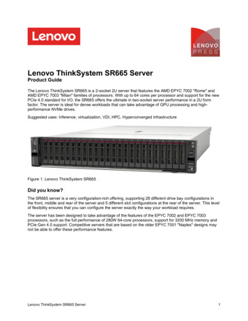
Transcription
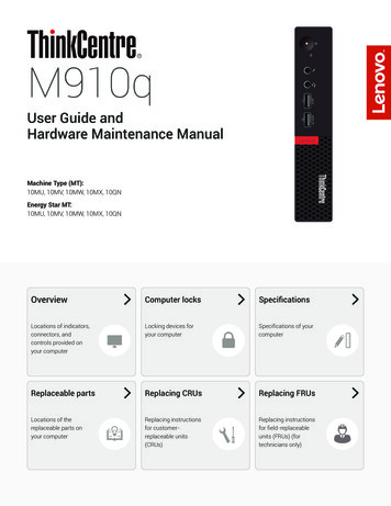
M910qUser Guide andHardware Maintenance ManualMachine Type (MT):10MU, 10MV, 10MW, 10MX, 10QNEnergy Star MT:10MU, 10MV, 10MW, 10MX, 10QNOverviewComputer locksSpecificationsLocations of indicators,connectors, andcontrols provided onyour computerLocking devices foryour computerSpecifications of yourcomputerReplaceable partsReplacing CRUsReplacing FRUsLocations of thereplaceable parts onyour computerReplacing instructionsfor customerreplaceable units(CRUs)Replacing instructionsfor field-replaceableunits (FRUs) (fortechnicians only)
ContentsOverview.3Front view. 3Rear view. 4System board. 6Replacing the external I/O box.26Replacing the power adapter bracket.27Removing the computer cover and dust shield.28Replacing the storage drive.29Machine type and model label. 7Replacing the internal speaker.30I/O box.8Replacing the Wi-Fi card.32Overview. 8Using the I/O box. 9Computer locks.10Attaching a Kensington-style cable lock.10Specifications.11Replacing the system fan.31Replacing the bottom cover.35Replacing the memory module.36Replacing the M.2 storage drive.37Completing the parts replacement.38Replacing FRUs.39Before replacing FRUs.39Replacing the illuminated red dot cable.41Replacing the advanced speaker.42Replacing hardware.12Before replacing hardware.12Handling static-sensitive devices.12Knowing replaceable parts.13Customer-Replaceable Units (CRUs). 13Field-Replaceable Units (FRUs). 13CRUs and FRUs locations. 14Replacing CRUs.17Before replacing CRUs.17Replacing the keyboard or wireless keyboard.19Replacing the keyboard. 19Replacing the wireless keyboard. 19Replacing the Wi-Fi antennas.43Replacing the front Wi-Fi antenna. 43Replacing the rear Wi-Fi antenna. 44Replacing the storage drive cable.46Replacing the heat sink.47Replacing the microprocessor.48Replacing the coin-cell battery.50Replacing the antenna bracket, system board, andchassis.52Notices & Trademarks.54Notices.54Trademarks.55Replacing the mouse or wireless mouse.20Replacing the mouse. 20Replacing the wireless mouse. 20Replacing the power adapter.22Replacing the vertical stand.23Replacing the VESA mount bracket.24Replacing the external optical drive box.25 2
OverviewFront viewNoteYour computer model might look slightly different from the illustration.1Power indicatorThis indicator is on when the computer is on.2Power buttonUsed to turn on your computer. When you cannot shut down thecomputer from the operating system, press and hold the powerbutton for four or more seconds to turn off the computer.3Storage drive status indicatorThis indicator is on when the storage drive is in use.4Microphone connectorUsed to connect a microphone to your computer. You can use themicrophone to record sounds or interact with the computer usingspeech-recognition software.5Headset connectorUsed to connect a headset or headphones to your computer.6USB 3.0 connectorUsed to connect a USB-compatible device, such as a USBkeyboard, mouse, scanner, printer, or personal digital assistant(PDA). For optimal data transfer, connect a USB 3.0 device to aUSB 3.0 connector instead of a USB 2.0 connector.7Always On USB 3.0 connectorUsed to connect a device that requires a USB 2.0 or USB 3.0connection, such as a keyboard, a mouse, a scanner, a printer,or a personal digital assistant (PDA). With the power adapterconnected, you can charge the automatically detected deviceeven when the computer is in hibernation mode or turned off.8Illuminated red dotThis indicator is on when the computer is powered on.Overview3
Rear viewNoteYour computer model might look slightly different from the illustration.9Optional connector 1Depending on the computer model, the connector might vary.10Optional connector 2Depending on the computer model, the connector might vary.11Security-lock slotUsed to secure a Kensington-style cable lock.12Wi-Fi antenna slotUsed to install the rear Wi-Fi antenna cable connector that isavailable only on some models. The rear Wi-Fi antenna is installedon the rear Wi-Fi antenna cable connector.13Ethernet connectorUsed to connect an Ethernet cable for network access.14USB 3.0 connectors (2)Used to connect a device that requires a USB 2.0 or USB 3.0connection.15USB 3.0 connectorUsed to connect a device that requires a USB 2.0 or USB 3.0connection.NoteOverviewThe USB 3.0 connector supports thesmart power on feature that enablesyou to turn on the computer or wakeit up from S4 hibernation mode bypressing Alt P on the keyboard. Youcan enable or disable the smart poweron feature from the Setup Utilityprogram. For detailed information, seeImportant Product Information Guide.4
16DisplayPort connectorUsed to send or receive audio and video signals. You can attacha compatible audio or video device to this connector, such as ahigh-performance monitor.17USB 3.0 connectorUsed to connect a device that requires a USB 2.0 or USB 3.0connection.18DisplayPort connectorUsed to send or receive audio and video signals. You can attacha compatible audio or video device to this connector, such as ahigh-performance monitor.19Power adapter connectorUsed to connect the power adapter to your computer for powersupply.Overview5
System boardNoteOverviewSee Front view or Rear view for additional component descriptions.1Serial connector 12Serial connector 23USB 3.0 connector4Storage drive fan connector5Microprocessor socket6Coin-cell battery7Illuminated red dot connector8Internal speaker or advanced speakerconnector9System fan connector10SATA storage drive connector11M.2 Wi-Fi card slot12Memory slot (DIMM1)13Memory slot (DIMM2)14M.2 storage drive slot6
Machine type and model labelThe machine type and model label identifies your computer. When you contact Lenovo for help, themachine type and model information helps support technicians to identify your computer and providefaster service.The machine type and model label is attached on the side of your computer as shown.Overview7
I/O boxOverviewNoteI/O boxDepending on your computer model, the I/O box might be optional.1USB 2.0 connectors (2)2Serial connector (optional)3USB 2.0 connectors (2)4USB 3.0 connectors (2)5USB 3.0 connector(for connecting to the computer)8
Using the I/O boxWhen you use the I/O box with the ThinkCentre tiny computer, note the following: The I/O box supports a maximum current rating of 5 A. It is recommended that you connect low-currentdevices to the I/O box and connect high-current devices directly to the ThinkCentre tiny computer toensure the best performance of the devices. The USB 2.0 connectors and USB 3.0 connectors on the I/O box provide a current of 500 mA and 900mA current, respectively. When you connect a high-current storage drive to only one USB connector, thesystem might not recognize the device. You can connect the storage drive to two USB connectors on theI/O box. The serial connector does not support hot swapping. Do not connect a device to the connector orremove a device from the connector while the system is running. The connectors on the I/O box cannot be enabled or disabled individually. To enable or disable any of theconnectors on the I/O box, enable or disable the USB connectors on the rear of the computer. The I/O box enables you to wake up the computer from standby mode through operations on devicesconnected to the I/O box connectors.I/O box9
Computer locksAttaching a Kensington-style cable lockYou can use a Kensington-style cable lock to secure your computer to a desk, table, or othernonpermanent fixture. The cable lock connects to the security-lock slot at the rear of your computer.Depending on the type selected, the cable lock can be operated with a key or combination. The cable lockalso locks the buttons used to open the computer cover. This is the same type of lock used with manynotebook computers. You can order such a cable lock directly from Lenovo by searching for Kensington at:http://www.lenovo.com/support.Computer locks10
SpecificationsPower supply 65 watt automatic voltage-sensing power supply 90 watt automatic voltage-sensing power supply (optional)Storage drivesUp to two storage drivesVideo featuresThe integrated graphics card supports the following: DisplayPort connectorsAudio featuresThe integrated audio card supports the following: Advanced speaker (optional) Headset connector Internal speaker Microphone connectorInput/Output (I/O) features Audio connectors (headset and microphone) DisplayPort connectors Ethernet connector Serial connectors (optional) USB connectorsExpansion External I/O box (optional) External optical drive box (optional) Memory slotsNetwork features Ethernet LAN Wireless LAN (optional) Bluetooth (optional)Physical dimensions Width: 35 mm (1.4 inches) Height: 183 mm (7.2 inches) Depth: 179 mm (7.1 inches)Weight (without the package)Specifications Maximum configuration as shipped: 1.3 kg (2.9 lb)11
Replacing hardwareBefore replacing hardwareAttentionDo not open your computer or attempt any repairs before reading the ImportantProduct Information Guide.Read these notes before replacing hardware: Some of the hardware components explained in this manual are optional. Use computer components provided only by Lenovo. When installing or replacing an option, use the appropriate instructions explained in this manual alongwith the instructions that come with the option. In most areas of the world, Lenovo requires the return of defective CRUs (Customer Replaceable Units).Information about this will come with the CRU or will come a few days after the CRU arrives.Handling static-sensitive devicesDo not open the static-protective package containing the new component until the defective componenthas been removed and you are ready to install the new component. Static electricity, although harmless toyou, can seriously damage computer components.When you handle parts and other computer components, take these precautions to avoid static damage: Limit your movement. Movement can cause static electricity to build up around you. Always handle parts and other computer components carefully. Handle PCI/PCI-Express cards, memorymodules, system boards, and microprocessors by the edges. Never touch any exposed circuitry. Prevent others from touching the parts and other computer components. Touch the static-protective package containing the part to a metal expansion-slot cover or otherunpainted metal surface on the computer for at least two seconds. This reduces static electricity fromthe package and your body before you install or replace a new part. When possible, remove the new part from the static-protective package, and install it directly in thecomputer without setting the part down. When this is not possible, place the static-protective packagethat the part came in on a smooth, level surface and place the part on the package. Do not place the part on the computer cover or other metal surface.Replacing hardware12
Knowing replaceable partsCustomer-Replaceable Units (CRUs)CRUs are computer parts that a user can upgrade or replace. There are two types of CRUs: self-service andoptional-service.Self-service CRUsYou can install self-service CRUs easily. These CRUs might be standalone,latched, or secured by up to two screws.Examples of self-service CRUs include the keyboard, mouse, any USBdevice, and the power cord. Other self-service CRUs might include memorymodules, adapter cards, hard disk drives, and optical drives.NoteOptional-serviceCRUsUsers are responsible for replacing all self-service CRUs.Handling optional-service CRUs requires some technical skills and simpletools (such as a screwdriver).These CRUs are isolated parts within the computer. They are usuallyconcealed by an access panel that is secured by more than two screws. Youmust remove the screws and panel to access the specific CRU.Optional-service CRUs can be removed and installed by users or, during thewarranty period, by a Lenovo service technician.Field-Replaceable Units (FRUs)FRUs are computer parts that a trained technician can upgrade or replace.For detailed FRU information, such as the FRU part numbers and supported computer models, go ing hardware13
CRUs and FRUs locationsRefer to the following illustrations to check the locations of CRUs and FRUs within the computer.NoteSome of the following parts are optional on some models.Self-service CRUReplacing hardware1Vertical stand2Power adapter bracket3Power adapter4Power cord5Computer cover6Dust shield16Bottom cover17Memory module18M.2 storage drive26VESA mount bracket27External optical drive28External optical drive box29External I/O box30Keyboard or wirelesskeyboard p. 1931Mouse or wireless mousep. 23p. 27p. 22p. 22p. 28p. 28p. 35p. 36p. 37p. 24p. 25p. 25p. 26p. 2014
Optional-service CRUReplacing hardware9Internal speaker13System fan20Storage drive21Storage drive bracket22Wi-Fi card shield23Wi-Fi cardp. 30p. 31p. 29p. 29p. 32p. 3215
FRU7Microprocessor8Coin-cell battery10Illuminated red dot cablep. 48p. 50p. 41Replacing hardware11Advanced speaker12Antenna bracket14System board15Chassis19Storage drive cable24Wi-Fi antennas25Heat sinkp. 42p. 52p. 52p. 52p. 46p. 43p. 4716
Replacing CRUsBefore replacing CRUsCustomer Replaceable Units (CRUs) are computer parts that a user can upgrade or replace. There are twotypes of CRUs: self-service and optional-service.To check the locations of CRUs, see CRUs and FRUs locations.AttentionDo not open your computer or attempt any repairs before reading the ImportantProduct Information Guide.Before replacing a CRU, click the illustration of the part to check the brief procedures.Keyboard or wirelesskeyboardMouse or wirelessmousePower adapterVertical standVESA mount bracketExternal optical driveReplacing CRUs17
External I/O boxPower adapter bracketDust shieldComputer coverStorage driveInternal speakerSystem fanWi-Fi cardBottom coverMemory moduleM.2 storage driveNoteReplacing CRUsTo replace a component that is not in the list above, contact a Lenovo servicetechnician. The support phone numbers are available at http://www.lenovo.com/support/phone.18
Replacing the keyboard or wireless keyboardNoteThe wireless keyboard is available only on some models.Replacing the keyboard1Disconnect the old keyboard cable from the computer.2Connect a new keyboard to the appropriate connector on the computer.Replacing the wireless keyboard1Remove your old wireless keyboard.2Take out the new wireless keyboard from the package.3Open the battery compartment cover, and install two AAA batteries according to the polarityindicators.4Remove the USB dongle from the keyboard compartment or from the wireless mouse compartmentand connect it to an available USB connector on the computer.5Close the compartment cover. The keyboard is ready for use.Replacing CRUs19
Replacing the mouse or wireless mouseNoteThe wireless mouse is available only on some models.Replacing the mouse1Turn off the computer and disconnect all power cords from electrical outlets.2Disconnect the old mouse cable from the computer.3Connect a new mouse to the appropriate connector on the computer.Replacing the wireless mouse1Disconnect the USB dongle from your computer. Then, remove your old wireless mouse.2Remove the new wireless mouse from the package.Replacing CRUs20
3Replace the wireless mouse.123456Note The green LED indicates that the mouse is ready for use. The flashing amber LED indicates a low battery level. Push the power switch to the off position when you are not using the mouse toextend the battery life. After disconnecting the USB dongle from your computer, store it in the wirelessmouse compartment or in the wireless keyboard compartment.Replacing CRUs21
Replacing the power adapterAttentionDo not open your computer or attempt any repairs before reading the ImportantProduct Information Guide.1Remove any media from the drives and turn off all connected devices and the computer.2Disconnect all power cords from electrical outlets and disconnect all cables that are connected tothe computer.3Replace the power adapter.NoteYour power cord might look different from the one illustrated.1234Replacing CRUs22
Replacing the vertical standAttentionDo not open your computer or attempt any repairs before reading the ImportantProduct Information Guide.1Remove any media from the drives and turn off all connected devices and the computer.2Disconnect all power cords from electrical outlets and disconnect all cables that are connected tothe computer.3Replace the vertical stand.1Replacing CRUs223
Replacing the VESA mount bracketAttentionDo not open your computer or attempt any repairs before reading the ImportantProduct Information Guide.1Remove any media from the drives and turn off all connected devices and the computer.2Disconnect all power cords from electrical outlets and disconnect all cables that are connected tothe computer.3Replace the VESA mount bracket.1Replacing CRUs224
Replacing the external optical drive boxAttentionDo not open your computer or attempt any repairs before reading the ImportantProduct Information Guide.1Remove any media from the drives and turn off all connected devices and the computer.2Disconnect all power cords from electrical outlets and disconnect all cables that are connected tothe computer.3Replace the external optical drive box.1234Replacing CRUs25
Replacing the external I/O boxAttentionDo not open your computer or attempt any repairs before reading the ImportantProduct Information Guide.1Remove any media from the drives and turn off all connected devices and the computer.2Disconnect all power cords from electrical outlets and disconnect all cables that are connected tothe computer and the external I/O box.3Replace the external I/O box.1Replacing CRUs226
Replacing the power adapter bracketAttentionDo not open your computer or attempt any repairs before reading the ImportantProduct Information Guide.1Remove any media from the drives and turn off all connected devices and the computer.2Disconnect all power cords from electrical outlets and disconnect all cables that are connected tothe computer.3Replace the power adapter bracket.1Replacing CRUs227
Removing the computer cover and dust shieldNoteThe dust shield is available only on some models.AttentionDo not open your computer or attempt any repairs before reading the ImportantProduct Information Guide.1Remove any media from the drives and turn off all connected devices and the computer.2Disconnect all power cords from electrical outlets and disconnect all cables that are connected tothe computer.3Remove the computer cover and dust shield.1Replacing CRUs228
Replacing the storage driveAttentionDo not open your computer or attempt any repairs before reading the ImportantProduct Information Guide.1Remove any media from the drives and turn off all connected devices and the computer.2Disconnect all power cords from electrical outlets and disconnect all cables that are connected tothe computer.3If your computer is installed with a front Wi-Fi antenna, disconnect the front Wi-Fi antenna cablefrom the Wi-Fi card.4Remove the computer cover. For details, see Removing the computer cover and dust shield.5Disconnect the storage drive cables from the system board.6Replace the storage drive.12347Connect the storage drive cables to the system board.8Reinstall the computer cover and reconnect the cables. For details, see Completing the partsreplacement.Replacing CRUs29
Replacing the internal speakerAttentionDo not open your computer or attempt any repairs before reading the ImportantProduct Information Guide.1Remove any media from the drives and turn off all connected devices and the computer.2Disconnect all power cords from electrical outlets and disconnect all cables that are connected tothe computer.3Remove the computer cover. For details, see Removing the computer cover and dust shield.4Disconnect the internal speaker cable from the internal speaker connector on the system board.5Replace the internal speaker.126Connect the internal speaker cable to the internal speaker connector on the system board.7Reinstall the computer cover and reconnect the cables. For details, see Completing the partsreplacement.Replacing CRUs30
Replacing the system fanAttentionDo not open your computer or attempt any repairs before reading the ImportantProduct Information Guide.1Remove any media from the drives and turn off all connected devices and the computer.2Disconnect all power cords from electrical outlets and disconnect all cables that are connected tothe computer.3Remove the computer cover. For details, see Removing the computer cover and dust shield.4Remove the storage drive. For details, see Replacing the storage drive.5Remove the internal speaker. For details, see Replacing the internal speaker.6Release the illuminated red dot cable from the system fan.7Disconnect the system fan cable from the system fan connector on the system board.8Replace the system fan.129Connect the system fan cable to the system fan connector on the system board.10Install the illuminated red dot cable to the new system fan.11Reinstall the computer cover and reconnect the cables. For details, see Completing the partsreplacement.Replacing CRUs31
Replacing the Wi-Fi cardAttentionDo not open your computer or attempt any repairs before reading the ImportantProduct Information Guide.1Remove any media from the drives and turn off all connected devices and the computer.2Disconnect all power cords from electrical outlets and disconnect all cables that are connected tothe computer.3Remove the computer cover. For details, see Removing the computer cover and dust shield.4Remove the storage drive. For details, see Replacing the storage drive.5Depending on your computer model, refer to one of the following to replace the Wi-Fi card. Type 11234Replacing CRUs32
56 Type 21234Replacing CRUs33
566Reinstall the computer cover and reconnect the cables. For details, see Completing the partsreplacement.Replacing CRUs34
Replacing the bottom coverAttentionDo not open your computer or attempt any repairs before reading the ImportantProduct Information Guide.1Remove any media from the drives and turn off all connected devices and the computer.2Disconnect all power cords from electrical outlets and disconnect all cables that are connected tothe computer.3Remove the computer cover. For details, see Removing the computer cover and dust shield.4Replace the bottom cover.152Reinstall the computer cover and reconnect the cables. For details, see Completing the partsreplacement.Replacing CRUs35
Replacing the memory moduleAttentionDo not open your computer or attempt any repairs before reading the ImportantProduct Information Guide.1Remove any media from the drives and turn off all connected devices and the computer.2Disconnect all power cords from electrical outlets and disconnect all cables that are connected tothe computer.3Remove the computer cover. For details, see Removing the computer cover and dust shield.4Remove the bottom cover. For details, see Replacing the bottom cover.5Replace the memory module.61234Reinstall the removed parts and computer cover. For details, see Completing the parts replacement.Replacing CRUs36
Replacing the M.2 storage driveAttentionDo not open your computer or attempt any repairs before reading the ImportantProduct Information Guide.1Remove any media from the drives and turn off all connected devices and the computer.2Disconnect all power cords from electrical outlets and disconnect all cables that are connected tothe computer.3Remove the computer cover. For details, see Removing the computer cover and dust shield.4Remove the bottom cover. For details, see Replacing the bottom cover.5Replace the M.2 storage drive.61234Reinstall the removed parts and computer cover. For details, see Completing the parts replacement.Replacing CRUs37
Completing the parts replacementAfter completing the installation or replacement for all parts, reinstall the computer cover and reconnectthe cables.To reinstall the computer cover and reconnect the cables to your computer, do the following:1Ensure that all components have been reassembled correctly and that no tools or loose screwsare left inside your computer. See System board for the locations of various components in yourcomputer.2Ensure that the cables are routed correctly before reinstalling the computer cover. Keep cablesclear of the hinges and sides of the computer chassis to avoid interference when reinstalling thecomputer cover.3Install the computer cover and dust shield.124Install the screw to secure the computer cover.5Place the computer in an upright position.6If a locking device is available, use it to lock the computer. See Locking the computer.7Reconnect the external cables and power cords to the corresponding connectors on the computer.See Front view or Rear view for the locations of various components in your computer.Replacing CRUs38
Replacing FRUsBefore replacing FRUsBefore replacing any Field Replaceable Units (FRUs), read the following: Only certified and trained personnel can service the computer. Before replacing an FRU, read the entire section about replacing the part. Be extremely careful during writing operations such as copying, saving, or formatting.The sequence of the drives in the computer that you are servicing might have been altered. If you select anincorrect drive, data or programs might be overwritten. Replace an FRU only with another FRU of the correct model.When you replace an FRU, ensure that the model of the machine and the FRU part number are correct byreferring to the website http://www.lenovo.com/serviceparts-lookup. An FRU should not be replaced because of a single, unreproducible failure.Single failures can occur for a variety of reasons that have nothing to do with a hardware defect, such ascosmic radiation, electrostatic discharge, or software errors. Consider replacing an FRU only when a problemrecurs. If you suspect that an FRU is defective, clear the error log and run the test again. If the error does notrecur, do not replace the FRU. Only replace a defective FRU.To check the locations of FRUs, see CRUs and FRUs locations.AttentionReplacing FRUsDo not open your computer or attempt any repairs before reading the ImportantProduct Information Guide.39
Before replacing an FRU, click the illustration of the part to check the brief procedures.Illuminated red dot cableAdvanced speakerWi-Fi antennasStorage drive cableHeat sinkMicroprocessorCoin-cell batteryAntenna bracketSystem boardChassisNoteReplacing FRUsTo replace a component that is not inthe list above, contact a Lenovo servicetechnician.The support phone numbers are availableat http://www.lenovo.com/support/phone.40
Replacing the illuminated red dot cableAttentionDo not open your computer or attempt any repairs before reading the ImportantProduct Information Guide.1Remove the computer cover. For details, see Removing the computer cover and dust shield.2Disconnect the illuminated red dot cable from the system board. See System board.3Replace the illuminated red dot cable.124Connect the illuminated red dot cable to the system board. See System board.5Reinstall the removed parts and computer cover. For details, see Completing the parts replacement.Replacing FRUs41
Replacing the advanced speakerNoteThe advanced speaker is available only on some models.AttentionDo not open your computer or attempt any repairs before reading the ImportantProduct Information Guide.1Remove the computer cover. For details, see Removing the computer cover and dust shield.2Remove the storage drive. For details, see Replacing the storage drive.3Disconnect the advanced speaker cable from the advanced speaker connector on the system board.See System board.4Replace the adva
Overview 6 System board Note See Front view or Rear view for additional component descriptions. 1 Serial connector 1 2 Serial connector 2 3 USB 3.0 connector 4 Storage drive fan connector 5 Microprocessor socket 6 Coin-cell battery 7 Illuminated red dot connector 8 Internal speaker or advanced speaker connector 9 System fan connector 10 SATA storage drive connector