Transcription
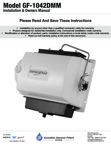
Model GF-1042DMMInstallation & Owners ManualPlease Read And Save These Instructions Installation by anyone other than a qualified contractor voids the warranty. Product designed for residential installation only. Commercial installation voids warranty.Modification or alteration of product, parts, installation instructions or local safety codes voids warranty. Read our full warranty policy at the end of this document.Our Brands Last Updated: 05-2021400 Midwest Rd.Toronto, ON M1P 3A9CanadaToll Free: (888) ca
Model 1042LH Humidifier Installation ManualModel 1042LH Table of ContentsPage #3334-567788910! WARNING! This symbol indicates: IMPORTANT INSTRUCTIONS!Failure to heed them can result in serious injury or death.! CAUTION! This symbol indicates: IMPORTANT INSTRUCTIONS!Failure to heed them can result in serious injury or material property damage.Our Brands Last Updated: 05-2021400 Midwest Rd.Toronto, ON M1P 3A9CanadaToll Free: (888) ca
Model 1042LH Humidifier Installation ManualSpecifications Model: GF-1042DMM Legacy Flow Through HumidifierType: Flow ThroughGPD: 17 Based on 120 F / 49 C Plenum TemperatureWarranty (Years): 5Replacement Vapor Pad : GF-990-13(Replace 1-2 times per season)Dimensions (Inches): 14 H x 15-1/8 W x 9 DWeight (Pounds): 13Home Size (Square Feet): To 3,000Installation: Warm Air Plenum / Right or LeftPlenum Opening (Inches): 9-1/2 H X 13-5/8 W15-1/8” WBypass Duct (Inches): 6Pallet Qty: 30Cabinet Construction: UV-Stable Automotive Grade PlasticHumidistat: Models: GF-MHX3 (Included)Voltage: 24VACIn Box: Humidifier, Humidistat, Installation Instructions, Vapor Pad , Parts Kit, Drain Hose,Transformer, Metal Distributor Tube, Damper, 15’ 5/8” Drain Hose, Drain Pan, SolenoidValve14” H9” DUnit Location WARNING: Disconnect electrical power before beginning installation.! Do not install where temperatures fall below 32 F / 0 C or where plenum temperatures exceed 200 F / 93 C.When wiring into a multi-speed blower circuit see Step 7D. The humidifier may be mounted with the 6" outlet to the right or left by inverting the cabinet and reversing thepositions of the distributor trough and drain pan. The humidifier may be mounted on the warm or return airplenum with equal efficiency.WarmAirReturnAirInstallation Options: Warm Air PlenumReturn Air PlenumVertical or HorizontalFurnace or Air HandlerAdditional Materials That May Be Necessary1.2.3.4.5.1/4" Diameter plastic supply tubing or 1/4" copper supply tubing for hot water applications6" Diameter galvanized by-pass pipeElectrical wire and wire nutsAir pressure switch (Model GF-12500)Current sensing relay (Model GF-GA50)Our Brands Last Updated: 05-2021400 Midwest Rd.Toronto, ON M1P 3A9CanadaToll Free: (888) ca
Model 1042LH Humidifier Installation ManualInstallation1. Select location on vertical surface of warm or return airplenum for mounting humidifier. For plenum sizes 9 1/2"to 15" use GP-1040AD adapter plate and five screws, 3screws in top (supplied with DM model only). Affixmounting template in place making sure the template islevel. Do not install humidifier or 6" bypass pipe wherethe blanked off ends of a cooling coil will restrict air flowto the humidifier. Extend horizontal centerline fromtemplate to the adjacent plenum. Scribe 6” circle 10” to15” from side of humidifier, on cabinet centerline, usingconnecting collar as guide. Cut out center section oftemplate and 6” hole.ALLOW 2 1/2 INCHES CLEARANCEABOVE THIS SURFACE FOR SERVICINGTop Of TemplateTEMPLATE FOR INSTALLINGBYPASS HUMIDIFIERFOLLOW INSTRUCTIONS PACKED WITH HUMIDIFIER1. REMOVE PROTECTIVE PAPER FROM BACK OF TEMPLATE AND STICK IN LEVEL POSITION.2. CENTER PUNCH AND DRILL THE FOUR SIDE MOUNTING HOLES WITH A 1/8 " DIA. DRILL.3. HANG HUMIDIFIER FROM FOUR SIDE SCREWS AND INSTALL DRAIN PAN, EVAPORATO RPAD AND DISTRIBUTOR TROUGH.WHEN INSTALLING ON BASEMENT TYPE FURNACE, EXTEND THIS LINEFOR LOCATING HOLE ON ADJACENT PLENUM4. TIGHTEN SCREWS AND ADJUST HUMIDIFIER UNTIL LEVEL.5. REMARK FOUR REMAINING HOLES IF NECESSARY.6. REMOVE HUMIDIFIER, DRILL REMAINING HOLES AND CUT OUT CENTER SECTION O FTEMPLATE.CUT ON THIS LINETEMPLATE NO. 1042-25IF FURNACE JACKET EXTENDS MORE THAN 3" OUTWARD FROM THE PLENUM SURFAC EALLOW 4" CLEARANCE BELOW THIS LINE FOR EASY ACCESS TO DRAIN HOSE CONNECTION.2. Install four sheet metal screws in the side mounting holesuntil the heads project about 3/8". Hang the humidifierfrom the four screws. Adjust humidifier until level andtighten four screws. Install four sheet metal screws in theremaining mounting holes. Tighten all 8 screws. Installdrain pan, evaporator pad and distributor trough.3.Install connecting collar. Connect by-pass pipe to collarand humidifier cabinet. Using holes at top and bottomof humidifier bypass opening, screw by-pass pipe tohumidifier cabinet.Our Brands Last Updated: 05-2021400 Midwest Rd.Toronto, ON M1P 3A9CanadaToll Free: (888) ca
Model 1042LH Humidifier Installation ManualInstallation, Cont.! CAUTION: Turn off water supply. not use plastic tubing on hot water or in contact with any hot plenum surface or duct.! CAUTION: Do Installation of this saddle valve must meet or exceed local codes and ordinances.4. Mount the Self-Tapping Saddle Valve.Copper Pipe:1.2.3.4.5.6.7.8.Retract piercing pin into valve body by turning handle counterclockwise.Screw valve body into upper bracket and tighten.Place rubber gasket over piercing pin.Assemble saddle valve over copper pipe using enclosed screws, nuts and lower bracket.Tighten screws evenly and firmly. Brackets should be parallel.Complete compression connection to saddle valve outlet.Turn handle clockwise to pierce tubing and close saddle valve.Turn handle counterclockwise to open saddle valve, leave open for several seconds to flush dirt from pipe and tubing.Steel, Brass or Hard Plastic Pipe:1.2.3.4.5.6.7.8.Shut off water supply and drain pipe.Turn handle clockwise to expose piercing pin and close saddle valve.Place rubber gasket over piercing pin.Drill 1/8" hole in pipe .Assemble saddle valve over steel, brass or hard plastic pipe using enclosed screws, nuts and lower bracket.Tighten screws evenly and firmly. Brackets should be parallel.Complete compression connection to saddle valve outlet.Turn handle counterclockwise to open saddle valve, leave open for several seconds to flush dirt from pipe and tubing.Threaded Pipe Fittings:1.2.3.4.5.Turn handle clockwise to expose piercing pin and close saddle valve.Seal valve body threads using pipe tape or sealant.Install valve into 1/8" NPT fitting.Complete compression connection to saddle valve outlet.Turn handle counterclockwise to open saddle valve, leave open for several seconds to flush dirt from pipe and tubing.5. Install the copper or plastic tubing.Connect 1/4” O.D. tubing to the saddle valve. Coppertubing requires a brass compression nut and brass sleeve.Plastic tubing requires a brass insert inside the tubing, aplastic sleeve on the outside with a brass compression nut.See figure to TUBINGPlasticSleeveBrassInsert6. Attach solenoid valve to side of humidifier cabinet with flowarrow pointing up, using thumb nuts provided. Do not reversebrass fittings as valve will not function if flow is reversed.Assemble distributor tube so that it is directed into the centeropening of the distributor trough cover. Connect 1/4" watersupply tube to brass filter at inlet of solenoid.! CAUTION: DO NOT USE PLASTIC TUBING IN CONTACT WITH ANY HOT PLENUM SURFACE OR DUCT. IF USING PLASTICTUBING, USE TUBE SUPPORT PROVIDED.Our Brands Last Updated: 05-2021400 Midwest Rd.Toronto, ON M1P 3A9CanadaToll Free: (888) ca
Model 1042LH Humidifier Installation ManualInstalling / Wiring The Control! WARNING: ALL WIRING SHOULD COMPLY WITH LOCAL ELECTRICAL CODES.Thin GasketThick GasketDUCT MOUNT: UseONLY Outer PortionDUCT MOUNT ONLYWALL MOUNT: UseOuter & Inner PortionsMountingBaseFIG. 1Face6. GF-MHX3: DUCT Mounting (Return Air Duct)! CAUTION 6. GF-MHX3: WALL Mounting Instructions: Do not install the humidistat on the warm air duct.1. Locate the humidistat at least 24" upstream of thehumidifier or bypass on the return air duct. Avoid areasof direct radiation like secondary heat exchangers in thefan compartment.2. Place template using level. Cut sensor hole as shown ontemplate. Drill four 3/32” holes (not shown).3. Remove the housing from the base by prying with asmall screwdriver at the notch in the side of the housing.1. Choose a location for the humidistat about five feetabove the floor on an inside wall with average roomtemperature and humidity conditions.2. Drill a small hole in the wall and run low voltage wiringto the location chosen. Pull about 6” of wire through thehole. Plug the opening to prevent drafts from affectingthe humidistat operation. Remove the housing from thebase by prying with a small screwdriver at the notch inthe side of the housing.4. Gaskets: Place the outer portion ONLY of the thin foamgasket on the humidistat base and mount the basewith four screws. Place the thick gasket inside the wallmount base to seal off air entering through the vents.Low voltage wire may enter the humidistat under thefoam seal.3. Gaskets: Place the entire outer and inner portions of thegasket on the base as shown. Do NOT install the thickgasket inside the base.5. Connect wires to screw terminals on the controlassembly as shown in wiring diagram. Replace housing.5. Connect wires to screw terminals on the control assemblyas shown in wiring diagram. Replace housing.SNSR24V. SOLENOID VALVEOUTDOOR TEMP. SENSORHUMFURNACECONTROL BOARDCW24v.60CY.WIRE JUMPERAC NAC LR4. Mount the base horizontally over the wires using level.Attach directly to the wall, using four screws provided.24V. SOLENOID VALVESNSROUTDOOR TEMP. SENSORHUMAC N6A6ANOC12500 AIRPRESSURE SWITCHWIREJUMPERAC L727-58 24 V. TRANSFORMERON-OFF SWITCH24V. SOLENOID VALVESNSR24V. SOLENOID VALVEOUTDOOR TEMP. SENSORHUMSNSRHUMWIREJUMPERAC NNAC LON-OFF SWITCH727-58 24 V. TRANSFORMEROur Brands Last Updated: 05-2021115v.(HOT)60CY.W 24v.60CY.FURNACEBOARDAC NOUTDOOR TEMP. SENSORWIREJUMPER115v.60CY.ON-OFF SWITCH727-58 24 V. TRANSFORMER6BFURNACEGA50CURRENTSENSINGRELAYCCOMMON LEADHILOCAC 6D400 Midwest Rd.Toronto, ON M1P 3A9CanadaToll Free: (888) ca
Model 1042LH Humidifier Installation ManualInstallation Final Steps7. Connect drain hose to 5/8" spout on humidifier cabinetusing hose clamp provided. Run 5/8" hose to suitabledrain such as floor drain, laundry sink or to a condensatepump (sold separately). Be sure hose has continuousslope and is not kinked at any point.8 Turn on water supply and check operation of humidifier.Set humidistat to a demand setting. With the furnace off,the solenoid valve should be closed. Start the furnace,the solenoid valve should open when the blower orburner circuit is energized. Check flow of water throughdistributor trough and evaporator pad. The standardGF-9903776 orifice will supply approximately 3.5 GPH ofwater at a line water pressure of 60 PSI. For low waterpressures (20-40 PSI) a larger orifice GF-9903775 isavailable to provide the same flow. Leave humidistat setat the recommended setting.How The Humidifier Works The operating principle of the humidifier is based on the most efficient and economical means ofevaporating water to the air. The humidifier uses only 2.5 watts of electrical power during operation, lessthan the smallest household light bulb. The heat necessary for evaporating water is produced by thefurnace. The water supply to the humidifier is controlled by the electric solenoid valve. The humidistatconnected in series with the solenoid provides low voltage control of the humidifier. The humidistat isdesigned for wall mounting in the living area or surface mounting on the return air duct. Water flows through a strainer, is metered through an orifice to provide the proper amount of water, and issupplied to the Vapor Pad by the distributor trough. Approximately 200CFM of air is by-passed from the warm air plenum through the humidifierand returned to the cold air plenum. Moisture is evaporated to the airAt OutsideRecommendedpassing through the evaporator pad.TemperatureSettingMinerals are not blown into the air stream as occurs in atomizinghumidifiers; they are left on the evaporator pad where a high percentage-20 F -29 C15%is carried off with the waste water.-10 F -23 C20% When the humidifier is installed and operating, no adjustments arenecessary other than setting the control knob on the humidistat to thedesired level of humidification. Set knob on the humidifier to "OPEN"position. To turn the humidifier off, close the water supply valve, switchelectrical power off and turn the humidistat off. If furnace is used forsummer cooling or ventilating set air damper on "CLOSED".0 F-18 F25% 10 F-12 C30% 20 F-7 C35% 30 F-1 C40% CAUTION: Do not set relative humidity too high during cold weather. Excessive humidity may cause! condensation on windows or in walls. Refer to recommended settings as described in the humidistat owners manual.Our Brands Last Updated: 05-2021400 Midwest Rd.Toronto, ON M1P 3A9CanadaToll Free: (888) ca
Model 1042LH Humidifier Installation ManualMaintenanceYour humidifier is engineered to give helpful and trouble-free humidification. For maximum efficiency the followingcleaning procedures should be carried out at the end of each heating season:1. Turn off the water supply and electrical power to the humidifier.2. Remove water distributor tube, distributor trough, used Vapor Pad and drain pan. The Vapor Pad may beremoved from either the top or bottom of the humidifier. Clean excessive mineral deposits from the distributortrough, drain pan and humidifier cabinet. A solution of 1/2 vinegar & 1/2 water will help loosen mineral deposits.3. Insert a new GF-990-13 Vapor Pad (black notch on top). Install trough and drain pan. Replace the distributortube to proper position over the distributor trough. Replace Vapor Pad yearly for peak performance.4. In heavy mineral areas, or if the solenoid valve fails to function, disconnect the 1/4” water supply line from thesolenoid valve. Remove the brass strainer body from the solenoid valve. Carefully pull the strainer screenGF-990-17 from the orifice fitting. Clean the mineral deposits from all parts. If the orifice is clogged, it may beopened by inserting a small needle. Reinsert the filter into the orifice fitting and screw the brass strainer body intothe solenoid valve.5. Reconnect the 1/4” water line to the solenoid valve if necessary. Turn on the water supply and check all points forleakage. The operation of the unit may be checked by starting the furnace. The humidifier operates only when thefurnace blower is running or the burner circuit is energized. The humidifier is now ready for operation.6. During the summer, turn OFF the water supply and electrical power to the humidifier. Close the air damper.Parts Drawing1099-9 THUMB NUT1137-35 TROUGH COVER1137-4 DISTRIBUTOR TROUGH1042-5 DISTRIBUTOR TUBE990-13 EVAPORATOR PADCABINET ASSEMBLY1042-16 (24 V.)P-103 COMPRESSION NUTP-104 COMPRESSION SLEEVEP-111 CONNECTORSOLENOID VALVE ASSEMBLY990-53 (24 V.)990-37-76 ORIFICE & STRAINER ASSEMBLY990-16-76 ORIFICE FITTING990-17 STRAINER SCREEN990-18 STRAINER BODY1137-3 DRAIN PANP-163 HOSE CLAMP1099-16 DRAIN TUBE
Model 1042LH Humidifier Installation ManualTroubleshooting1. My humidifier continues to run.Check for the following: The valve might be stuck in the "open" position. Check for wiring errors. Is the unit sized properly for your home? If it is rated for a smaller-sized home than the home in which it isinstalled, it will work "overtime" to reach the humidification levels desired. Check the Vapor Pad . If it is clogged, the pad will reduce the humidifier efficiency. Replace if necessary.2. My solenoid valve is making a "chatter" noise.This can be caused by any of the following: The power to the valve is less than 18V AC. The solenoid is causing a "water hammer condition" thru the water pipes (valve closes quickly and shuts offwater flow, which in turn creates pressure behind the valve that has no avenue of relief). You may want to installa water hammering device with your plumbing, or contact your local plumber to determine the best solution. The humidistat is located too close to the humidifier or the by-pass pipe. Your humidistat should be a min. of1.5' away or greater. The humidistat could have a buildup of dust, causing a faulty reading. Clean. The solenoid valve might be dirty. Remove, inspect and clean if necessary. Water supply pressure going to the valve may be too low. The hold down nut on top of the solenoid, as it may be loose.3. The humidifier is not raising the humidity levels in my home.Check for the following: Ensure you have changed / replaced your Vapor Pad at the proper intervals (once per year) to ensure thegreatest production of moisture.Check the setting of your humidistat to ensure it is set higher than current humidity levels in your home (when indoubt, turn it all the way to the right at maximum production). If you don't know what your current humiditylevel is, use an instrument called a thermo-hygrometer (Model GF-610) to measure both heat and humiditylevels in your home.Calculate your humidity load (Gallons Per Day - GPD) via our humidity calculator (www.GeneralAireIAQ.ca).Check to see that your humidifier model is designed to produce the amount of moisture (GPD) you need.Have you recently installed hardwood floors? Have you recently remodeled and added on to your home? Thesecan both increase your home's demand for humidity. Options include connecting your humidifier to the hotwater supply (which can increase output by as much as 30%), or installing a new humidifier model that cangenerate more humidity.The unit is not recommended for heat pumps.Plenum temperatures must meet or exceed 120 F to achieve listed capacities.4. My humidifier will not turn on.The following might be occurring: Check to see if your humidifier is plugged in, that the breaker is engaged, and that power to other items fromthe same source is working.Check that the damper knob is in the "OPEN" position.Ensure a fuse has not blown.Check that connectors are properly inserted in the terminal block.Make sure the furnace is operating in the heat mode.To ensure your safety and the longevity of your unit, we recommendcontacting a licensed contractor to perform any repairs or maintenance.! Our Brands Last Updated: 05-2021400 Midwest Rd.Toronto, ON M1P 3A9CanadaToll Free: (888) ca
Model 1042LH Humidifier Installation ManualFAQ’s1. How does a humidifier help with my allergies?Dry air can lead to a host of problems for allergy and asthma sufferers. Dry climates, winter air, and artificialheat all contribute to the discomfort by drying out your skin, throat and delicate sinus passages and airways(which can contribute to sinusitis). Winter is an especially bad time for dry air as home heating systems,especially forced-air systems, reduce the amount of moisture in the air while humidity levels outdoors typicallydip as well.2. What range of humidity is ideal?Research shows that 40-60% relative humidity is ideal. Outside this range, your risk of being adversely affectedincreases.3. How often should I change my Vapor Pad ?We recommend replacing your Vapor Pad at least once per year. Minerals build up on the vapor pad overtime, which in turn: Reduces the pad's ability to absorb water. Prevents the warm air from flowing through the pad. (Warm air moving though the water-soaked padcauses the water in the pad to evaporate. It is this process that delivers moisture throughout your homevia the home's duct system.)4. Can I clean my Vapor Pad instead of replacing it?A coating is applied to the Vapor Pad that helps it absorb water and control water flow. If you subject theVapor Pad to cleaning, you usually remove much of the coating and the pad becomes ineffective. Thisreduces the output of the humidifier and increases water consumption.Replace the Vapor Pad annually.5. Why would I want to install a humidifier?For many reasons:1. Since the air in your home is always trying to reach its saturation point, it will absorb water whereverit can; from the bodies of you and your children, your pets, your furniture and even your house plants.As a result your skin, throat and nasal passages dry out, leaving you more susceptible to physicaldiscomfort, colds, flu and even infection. Allergy and asthma sufferers can be especially affected by airthat's too dry.2. Dry air causes dry, itchy skin.3. Dry air cracks expensive woodwork, floors, musical instruments, artwork and furnishings.4. Annoying static electricity (caused by dry air) can damage computers, VCR’s and other electronicequipment, requiring expensive repair.5. Dry air can cause harm to expensive musical instruments like pianos and violins.6. Dry air causes gaps in window & door frames, letting cold outdoor air in; causing you to turn up the heatand increasing your heating bills! Controlled humidity from a GeneralAire Humidifier allows you theluxury of dialing the thermostat back & reducing annual heating bills. For example, 68 at 40% relativehumidity feels just as warm as 74 at 20% humidity. Setting your thermostat back by as little as threedegrees can reduce annual heating bills by as much as 5%.Our Brands Last Updated: 05-2021400 Midwest Rd.Toronto, ON M1P 3A9CanadaToll Free: (888) ca
2. Install four sheet metal screws in the side mounting holes. until the heads project about 3/8". Hang the humidifier from the four screws. Adjust humidifier until level and tighten four screws. Install four sheet metal screws in the remaining mounting holes. Tighten all 8 screws. Install drain pan, evaporator pad and distributor trough. 3.