Transcription
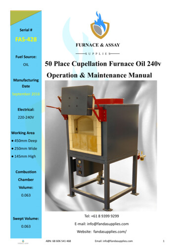
Serial #FAS-428FURNACE & ASSAY——SFuel Source:OILManufacturingDateU P P L I E S—––50 Place Cupellation Furnace Oil 240vOperation & Maintenance ManualSeptember 2016Electrical:220-240VWorking Area 450mm Deep 250mm Wide 145mm HighCombustionChamberVolume:0.063Tel: 61 8 9399 9299Swept Volume:E-mail: info@fandasupplies.com0.063Website: fandasupplies.com/ABN: 68 606 541 468Email: info@fandasupplies.com1
Manual IndexSystem Overview3-4Spare Parts List5-6Installation Procedure7Warm-up Procedure8Operating Instructions9Package Burner Data Sheet10-18Weekly Check List19Balancing Extraction20Maintenance21-31-Installing Muffle Chamber-Installing Floor Tiles-Door Repacking24-2627-2829-31Contact Details32ABN: 68 606 541 468Email: info@fandasupplies.com2
System OverviewConstruction960 mm Base construction uses high-quality 50 x 50RHS. Furnace body construction is durable 2mmlaser-cut plate High quality refractory brick and insulation Bolt holes in base plates of all 4 legs forindividual adjustment on uneven surfaces Counterbalanced door with manual lever toopen Optional port viewing window in door Vent Tube height 1160mm1750 mm760mm80mm1110 mmAVERAGE BURNER EQUIPMENT DEPTHShipping 1510mmISPM 15 Heat treatedexport KGPlease note you will require a minimum of 1 metre clearance around the furnace.* Dimensions are approximate only and may vary slightly with each furnace.ABN: 68 606 541 468Email: info@fandasupplies.com3
System Overview:This furnace has a fan forced single burner system, with an automaticIgnition System.Temperature is monitored and modulated automatically by a Type Kthermocouple system and Omron temperature controller, pre-set for amaximum temperature of 1100 degrees Celsius. This controller is simpleto operate, and has a 2-level display (PV and SV), that shows actualtemperature as well as the temperature the furnace is set to.Riello Burner SystemABN: 68 606 541 468Email: info@fandasupplies.com4
Parts List for FAS-160-OIL50 Place Cupellation Furnace, 240v OILRecommended 12 Months ConsumablesFAS -603FAS-803FAS-1008FAS DescriptionMuffle #4 to suit E50PCF & 50PCFVent Slotted #4 to suit E50PCF & 50PCFFloor Tile 450x250x15mm to suit E50PCF & 50PCFThermocouple Cupellation 230mm plus 75mm bendThermocouple Inner Sheath 250x10mmThermocouple Outer Sheath 250x15mmCeramic Anchor, (Complete) 3"Isowool Blanket (Kaowool) 160kg x 25mmRefractory Mortar 2 KGQty3566551211Recommended Critical Spare PartsFAS Part#FAS-648FAS DescriptionTemperature Controller, Omron E5CZ R2MTC-500 (Relay)Qty1Recommended Spare PartsFAS Part#FAS-160-DOORFAS-411FAS-608FAS-802FAS Description50PCF Door, factory lined (No Hinges or pins)Porcelain 2-way Element ConnectorsThermocouple WireIsowool Blanket (Kaowool) 128kg x 50mmQty1132For Burner equipment spare parts seeRiello parts list below.ABN: 68 606 541 468Email: info@fandasupplies.com5
Associated Spare PartsFAS AS-1003FAS-1004FAS-1007FAS Description50PCF New Body and Bricks50PCF Burner Equipment Oil 110/240v50PCF Door and Hinge50PCF Back Extraction Piece50PCF Refractory Reline Kit (no muffle/vent/tile)Max 4 Ecoflam Burner Oil 240vToggle Switch ( on/off, high/low )Surge Protector *240V*Isowool Blanket (Kaowool) 128kg x 25mmFlue Block - SmallBurner Port Square Hole 230x250mmRefractory Mortar 25kg DrumRefractory Mortar 1KGFor pictures, data sheets and more info on spare parts please go to productstab on our website http://www.fandasupplies.com/productsABN: 68 606 541 468Email: info@fandasupplies.com6
Installation ProcedureUnpack furnace from crate and store in dry area. Thefurnace usually has timber supports installed inside fortransport. Remove before operation.Furnace requires a min of 1 metre space around itto carry out maintenance / repairsInstall fuel oil supply Min. 1m head, Max. 5m head witha min of 3/8” line. Max. distance run 20m (if storagetank does not comply we suggest you install asecondary tank close to the furnace with a min height ifmetre. A 2 way filter system should be installed beforefurnace inlet. This allows cleaning without shuttingfurnace down.Electrical box is fitted with 3 core flex. If power socket isavailable connect correct type plug and turn on. If notthen an electrician is to either install correct socket orhard wire furnace to power supply.NOTE: THIS FURNACE USES SINGLE PHASEPOWER WITH A NEUTRAL WIRE AND EARTH.BEFORE STARTING CHECK THAT ALL EXHAUST DUCTING IS INPLACE.ABN: 68 606 541 468Email: info@fandasupplies.com7
Warm Up ProcedureMUFFLE START UP FROM COLD FIRST TIME.Once muffle is in place and rear vent has been installed into furnace:For LPG, NG and Diesel Furnaces:- Turn Furnace onto low fire for 15 mins, turn off for 15 mins, repeat for 1hour with door open.- Shut furnace door and start on low fire, run until reaches 500 C- Hold 500 C for minimum of 1 hour.- Increase temperature 100 C every hour up to normal running conditions.Keep a close eye on any cracks that may develop, this is indicated by moisture seeping through refractory. If you see this then maintain temperatureuntil moisture clears.Ongoing use after the initial commissioning ofmuffle and vent as follows:FURNACE START UP ONCE SHUT DOWN FOR 36 HOURS- Start furnace on low fire for a minimum of 2 hours.- Set temperature to 500 C and run for another 1 hour.- Set temperature to normal running conditions and muffle is ready foruse.ABN: 68 606 541 468Email: info@fandasupplies.com8
Operating Instructions1-Turn on Diesel Supply2-Turn on Main Switch.3-Set to required temperature.4-Turn on Burner Switch(Burners will take approximately 70 seconds to fire)Burners will modulate between on and off to maintainthe set temperature.Shutdown Procedure1-Turn off Burner Switch2-Isolate Diesel SupplyABN: 68 606 541 468Email: info@fandasupplies.com9
Riello Package BurnerTechnical Data SheetsABN: 68 606 541 468Email: info@fandasupplies.com10
ABN: 68 606 541 468Email: info@fandasupplies.com11
ABN: 68 606 541 468Email: info@fandasupplies.com12
ABN: 68 606 541 468Email: info@fandasupplies.com13
ABN: 68 606 541 468Email: info@fandasupplies.com14
ABN: 68 606 541 468Email: info@fandasupplies.com15
ABN: 68 606 541 468Email: info@fandasupplies.com16
ABN: 68 606 541 468Email: info@fandasupplies.com17
ABN: 68 606 541 468Email: info@fandasupplies.com18
Weekly ChecklistPressure readingsDateAir PressureOil pressureABN: 68 606 541 468InspectionsFlueCleanClean BurnerDoor BlanketBlower MoGeartorEmail: info@fandasupplies.comUv Cell ValueMicro amps19
Balancing the ExtractionThis is a basic overview of how an extraction system is set up.Typical cupelling extraction systemFumes are extracted to a bg house outside the laband the lead is filtered into the bg houseVENT TUBEBURNERExtraction unitBag HouseTo make sure you have the correct Extraction air flow, you will need an AnemometerPlace Anemometer in front of one of the Vent holes located at the back of the furnace.ABN: 68 606 541 468Email: info@fandasupplies.com20
MaintenanceRegular maintenance is required to make sure furnace is running correctly.It is important to keep the flue areas clean and regularly change floor tile.A good clean combustion chamber will allow the furnace to run efficiently.Check that muffle chamber has no cracks and if so then seal with someRefractory cement. The life of the chamber depends on several factors:A) Keeping the rear vent clean. If blocked then Pb will stick to the walls of thechamber thus increasing the density of the chamber. The furnace thenneeds to use additional gas to maintain temperature of the chamber andwill have longer cupelling times.It is very important to keep the rear vent clean.ABN: 68 606 541 468Email: info@fandasupplies.com21
If blocked Pb will stick to the walls of the chamber reducing the life of the Muffle.This also increases the density of the chamber.The furnace will then need to use additional power to maintain temperature ofthe chamber and will have longer cupelling times. Your muffle chamber will alsolast longer if you keep everything clean.To do this you will need a vent cleaning tool, or a piece of metal or jimmy bar toream the vent out. Make sure the vent has been cleaned all the way through,not just at the front. You may need to shine a torch into the vent to see yourprogress.Regularly change or clean the floor tile along with the bone ash forcollection of spills.ABN: 68 606 541 468Email: info@fandasupplies.com22
Keep the floor areas around the furnace clean and free of dirt, as it will layer ontothe transformer and control equipment.This chokes the equipment, making it run hotter and it may over heat.Remember a Muffle is a consumable item in a furnace. You must change a muffleout at least 2 – 3 times a year if looked after correctly. If little or no maintenance isdone on a furnace, the chamber can last as little as 1 month. If the muffle is leftunchanged, the brick work of the furnace will be eaten away. This will severelyreduce the life of your furnace.Spills clogging the burner port, due to poormaintenanceFailing to change Muffle/Vent when required.Note the damage to the brick work.ABN: 68 606 541 468Email: info@fandasupplies.com23
Installing Muffle ChamberWhen replacing a muffle remove old muffle and vent. Ensure that all debris is removed.Before installing new muffle you must make sure that the back wall, back ledgeand front ledge are clean and smooth. Also while the Muffle is out it is a good timeto clean out any build up in the Burner Port.Note: If the back wall, back ledge and front ledge are not cleaned properly, themuffle will not sit correctly, meaning the muffle will not work correctly, and will notlast as long.ABN: 68 606 541 468Email: info@fandasupplies.com24
Installation of muffle chamberremove thermocouple firstremove rear extraction if fittedSlide muffle chamber into positioncheck that muffle is positioned correctlyslide in vent tube from rearABN: 68 606 541 468Email: info@fandasupplies.com25
using strips of ceramic fibre seal around front ofchamber and rear ventSeal front and back of muffleand vent with thin layer ofrefractory cement.This will help to protect theceramic fibre duringoperation.Note: if seal has been damaged then replace as soon as possible.Place some magnisite powder on floor(about 15-20mm) thick then install floor tileRe-install Thermocouple and Lead extractor.ABN: 68 606 541 468Email: info@fandasupplies.com26
Installing Floor TilesThis method can apply to all fusion and cupel furnaces .Reason: To stop the tile from sticking to the furnace or muffle floor so it can beeasily removed when needs to be replaced.If tile does not crack it is also possible to reuse the tile on the opposite side.Each time you replace a tile you must scrape out the old mabor powder (or boneash) and replace with new.Mabor powder is used to soak up any spills you have during fusion or cupellationprocesses.The following is a tile install for a Cupellation furnace.Step 1Shovel Mabor powder or similar productonto the floorStep 2Using a flat edge, flatten off so that powder isabout 1/2” thick. Make sure the service is levelfrom front to back.Step 3Place floor tile into position and settle downflat.ABN: 68 606 541 468Email: info@fandasupplies.com27
Step 4Sprinkle a little powder on top of tiles readyfor the first pour. If a spillage occurs thenscrape out to the front of the furnace andsprinkle powder back on the floor.By following this practice your tiles will last longer and the furnace will stay clean.SummaryA good clean combustion chamber will allow the furnace to run efficiently.To do this and to extend the life of your muffle and your furnace, regularly checkthat muffle chamber has no cracks, if so then seal with some refractory cement.Make sure a floor tile is always installed,with about 15mm of Bone Ash underneathit.Keep the back Vent clean and clear, andchange it when needed.Regularly scrape and clean the floor tile. Ifthere is build up on one side, flip the tileover to double its life. Change floor tileregularly.Regular maintenance is required to makesure furnace is running correctly.Maintain Door ceramic blanket. If in poorcondition change.ABN: 68 606 541 468Email: info@fandasupplies.com28
Door RepackingFirst, second and third layerCut 3 x 25mm Isowoolwide (or 1x50mm & 1 x25mm) wideand fill the inside of thedoor, making sure all 3layers are tucked underthe door’s lips.Fourth LayerCut 25mm Kaowool so it fits on theinside lip of the doorFinal layerCut 25mm Kaowool to thelength of the door plus 40mm(width roll width) and place sothat a 20mm overhang of kaowoolis present on the edges shown.ABN: 68 606 541 468Email: info@fandasupplies.com29
Using a guide like a screw driver, pushup through the existing anchor holes inthe door’s body, keeping the guidestraight until it comes through top layerof kaowool. Once guide is throughwiggle around to make a slightly biggerhole.Place a screwdriver through the hole(isowool side up) then the cutter over thescrewdriver (a piece of pipe with a circumferenceof about 25mm by 100mm long with a mark about50mm up). Keeping the cutter at 90 deg, cutdown to marked line in cutter (50mm) and pullout. Knock out isowool stuck in cutter.Once cutter is pulled out there is a hole bigenough to place anchor through.ABN: 68 606 541 468Email: info@fandasupplies.com30
Screw anchors into holes cut out bycutter in kaowool until the boltscome through the pre drilled anchorholes in the door’s body. Once boltis through secure with a wing nut.Once all anchors have beeninstalled, use a straight edged,flat piece of wood and a sharp knifeto cut off overhanging isowool.Make sure the straight edge is linedup flush with the outer lip of furnacedoor top and bottom. Push straightedge down firmly and cut off excessisowool.ABN: 68 606 541 468Email: info@fandasupplies.com31
Contact DetailsFURNACE & ASSAY——SU P P L I E S—––Unit 5, 4 Dickens PlaceArmadale, 6112Western Australia, AustraliaPhone 61 8 9399 9299Fax 61 8 9399 s.comABN: 68 606 541 468Email: info@fandasupplies.com32
50 Place Cupellation Furnace Oil 240v Operation & Maintenance Manual FURNACE & ASSAY —— SUPPLIE S— -- Serial # FAS -428 Fuel Source: OIL Manufacturing Date September 2016 Electrical: 220 -240V Working Area 450mm Deep 250mm Wide 145mm High Combustion Chamber Volume: 0.063 Swept Volume: 0.063