Transcription
ENERGYSMARTSTANDARDVACATIONGRIDENABLEDF F/ CResidential ElectricWater HeaterInstallationInstructions andUse & Care GuideTo obstain technical, warranty, or service assistance during or after theinstallation of this water heater, visit our website at:http://www.whirlpoolwaterheatersupport.comor call tool free1-877-817-6750When calling for assistance, please have the following information ready:1. Model Number2. 7 Digit Product Number3. Serial Number4. Date of Installation5. Place of PurchaseTable Of ContentsPAGEWater Heater Safety . 2Installing Your Electric Water Heater . 3-9Unpacking Instructions . 3Location Requirements . 4Water System Piping . 5Electrical Requirements . 7Installation Checklist . 9Operating Your Water Heater . 10-12Water Heater Start-Up . 10Water Temperature Regulation . 10Energy Smart Module/Operational Modes . 11Electronic Thermostat . 12Smart Grid Technology . 13Operational Conditions . 14Maintenance of Your Water Heater . 15-23Diagnostic Code (ESM).17-18Diagnostic Code (ET). 19-20Trouble Shooting Chart .21Repair Parts illustration . 22Thermostat Wiring Diagram . 23PRINTED IN THE U.S.A 04111LOW LEADCOMPLIANTPART NO. 318686-000
WATER HEATER SAFETYYour safety and the safety or others are very important.We have provided many important safety messages in this manual and on your appliance. Always read and obey allsafety messages.This is the safety alert symbol.This symbol alerts you to potential hazards that can kill or hurt you and others.All safety messages will follow the safety alert symbol and either the word “DANGER” or“WARNING”. These words mean:DANGER: indicates an imminently hazardous situationwhich, if not avoided, will result in death or injury.WARNING: indicates a potentially hazardous situationwhich, if not avoided, could result in death or injury.All safety messages will tell you what the potential hazard is, tell you how to reduce the chance of injury, and tell youwhat can happen if the instructions are not followed.Important Safety InstructionsIMPORTANT: Hydrogen gas is produced in a hot water system served by this heater that has not been used for a longperiod of time (2 weeks or more). Hydrogen is extremely flammable. To reduce the risk of injury under theseconditions, it is recommended that the hot water faucet be opened for several minutes at the kitchen sink before usingany electrical appliance connected to the hot water system. When hydrogen is present, there will probably be an unusalsound such as air escaping through the pipe as the water begins to flow. There should be no smoking or open flamenear the faucet at the time it is open.The California Safe Drinking Water and Toxic Enforcement Act requires the Governor of California to publish a list ofsubstances known to the State of California to cause cancer, birth defects, or other reproductive harm, and requiresbusinesses to warn of potential exposure to such substances. WARNING: This product contains a chemical known to the State of California to cause cancer, birth defects, or otherreproductive harm. This appliance can cause low-level exposure to some of the substances listed in the Act.2
INSTALLING YOUR WATER HEATERConsumer InformationInsulation BlanketsThe use of an insulation blanket on this water heater isnot needed nor recommended. The purpose of an insulation blanket is to reduce the standby heat loss encountered with storage tank heaters. Your water heater meetsor exceeds the National Appliance Energy ConservationAct standards with respect to insulation and standby lossrequirements, making an insulation blanket unnecessary.This water heater should be installed in accordancewith the local code authority having jurisdiction, thepower company or electric utility, and this installationmanual. In the absence of local code requirements,follow the regulations set forth in the latest edition of theNational Electric Code, NFPA70. This is available fromthe following:National Fire Protection Agency1 Batterymarch ParkQuincy, MA 02269American National Standards Institute1430 BroadwayNew York, NY 10018Check your phone listings for the local authoritieshaving jurisdiction over your installation.Unpacking the Water HeaterWARNINGRemoving Packaging MaterialsExcessive Weight HazardUse two or more people to move and installwater heater.Consumer ResponsibilitiesFailure to do can result in back orother injury.This manual has been prepared to acquaint you withthe installation, operation, and maintenance of your electric water heater and provide important safety informationin these areas.We urge you to read all of the instructions thoroughly before attempting the installation or operation of this waterheater. This manual should be kept for future reference.The manufacturer of this water heater will not be liable forany damages caused by failure to comply with the installation and operating instructions outlined in this manual.If you lack the necessary skills required to properlyinstall this water heater or you have difficulty followingthe directions, you should not proceed but have aqualified person perform the installation of this waterheater.Examples of a qualified personnel include:licensed plumbers, authorized electric company personnel, and authorized service person.Massachusetts code requires this water heater to beinstalled in accordance with Massachusetts Plumbingand Fuel Code 248-CMR 2.00: State Plumbing Code and248-CMR 5.00.A data plate identifying your water heater can be foundadjacent to the energy smart module. When referring toyour water heater always have the information listed onthe data plate readily available, to include the model andserial number.Retain your original receipt as proof of purchase.IMPORTANT: Do not remove any permanent instructions,labels, or the data label from outside of the water heater oron the inside of panels. 3Remove exterior packaging and place installationcomponents aside.Do not remove the envelope bag containing thewater heater literature from the side of the waterheater.Inspect all parts for damage prior to installation andstart-up.Completely read and understand all instructionsbefore attempting to assemble and install this product.Replace this manual inside the envelope bag wheninstallation is complete.After installation, dispose of packaging material inthe proper manner.
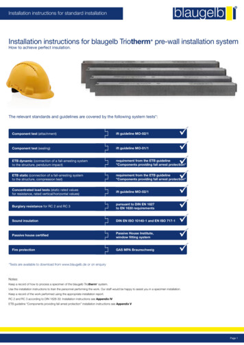
Location RequirementsSite locationSelect a location near the center of the water pipingsystem. It must be installed indoors and in a verticalposition on a level surface, in an area where waterleakage will not cause consequential damage.NOTE: Local codes and requirements in your area mayrequire the water heater to be installed such that thebottom element is elevated from the floor at least 18inches.The water heater should be located in an area notsubject to freezing temperatures. Water heaters locatedin unconditioned spaces (i.e., attics, garages, basements, etc.) may require the water piping and drainpiping to be insulated to protect against freezing. Thedrain and controls must be easily accessible for operation and service.NOTE: The water heater shall be located so it is notsubject to physical damage by moving vehicles or areaflooding.Figure 2Residential GarageInstallationKeep combustibles such as boxes, magazines, clothes,etc., away from the water heater area.Do not use this water heater in conjunction with a spa orhot tub.ENERGYSMARTSTANDARDVACATIONGRIDEMABLEDF F/ CVehicleStopIMPORTANT: The water heater should be located inan area where leakage of the tank or connections willnot result in damage to the area adjacent to the waterheater or to lower floors of the structure. Due to thenormal corrosive action of the water, the tank willeventually leak after an extended period of time.Also, any external plumbing leak, including thosefrom improper installation, may cause earlyfailure of the water tank due to corrosion if notrepaired. If the homeowner is uncomfortable withmaking the repair, a qualified person should becontacted. A suitable metal drain pan should beinstalled under the water heater as shown below. Thismetal drain pan is to protect the property from damagewhich may occur from normal condensate formationon the tank or leaks in the tank and pipe connections.The metal drain pan must limit the water level to amaximum depth of 2-1/2 inches and be two incheswider than the heater and piped to an adequate drain.Locate the water heater near asuitable indoor drain. Outdoor drains are subject tofreezing temperatures which can obstruct the drainline. The piping should be at least 3/4”ID and pitchedfor proper drainage.Under no circumstance will the manufacturer orseller of this water heater be held liable for anywater damage that is caused by your failure tofollow these instructions.DrainMetal Drain PanState of CaliforniaNOTE: The water heater must be braced, anchored, orstrapped to avoid moving during an earthquake. Contactlocal utilities for code requirements in your area or call1-877-817-6750 and request instructions.2 1/2” MaxPipe toadequatedrainAt least 2” inches greater thanthe diameter of the waterheater.Figure 14
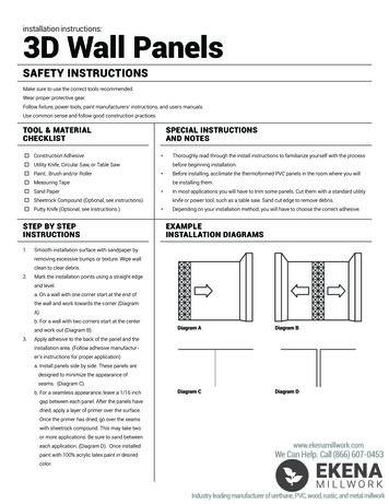
Water System PipingPiping InstallationPiping, fittings, and valves should be installed accordingto the installation drawing (Figure 3). If the indoor installation area is subject to freezing temperatures, thewater piping must be protected by insulation.Figure 3Water Piping InstallationIn a Closed System use aThermal Expansion Tank.Water supply pressure should be around 50 to 60 psiand should not exceed 80 psi. If this occurs, a pressurereducing valve should be installed in the cold water inletline. This should be placed on the supply to the entirehouse in order to maintain equal hot and cold waterpressures.IMPORTANT: Heat cannot be applied to the water fittingson the heater as they may contain nonmetallic parts.If solder connections are used, solder the pipe to theadapter before attaching the adapter to the hot and coldwater fittings.Pressure ReducingValve With BypassHot WaterOutletCold WaterInlet ValveUnionENERGYSMARTSTANDARDVACATIONCold WaterSupply toFixturesGRIDENABLEDFMainWaterSupply F/ CTemperature andPressure Relief ValveDischarge line 6” maximumabove drainIMPORTANT: Always use a good grade of joint com-pound and be certain that all fittings are drawn up tight.1. Install the water piping and fitting as shown inFigure 3. Connect the cold water supply (3/4” NPT)to the fitting marked “Cold”. Connect the hot watersupply (3/4” NPT) to the fitting marked “Hot”.Drain line3/4” IDminimum1”Min.DrainMetal Drain Pan2-1/2” depth max.IMPORTANT: Some models may contain energy savingheat traps to prevent the circulation of hot water withinthe pipes. Do not remove these inserts.2. The Installation of dielectric unions in both the hotand cold water supply lines is recommended forease of removing the water heater for service orreplacement.3. Some local codes may require, and the manufacturer of this water heater recommends,installing a mixing valve in the domestic hot waterline as shown in Figure 4. These valves reduce thepoint-of-use temperature of the hot water by mixingcold and hot water and are readily available.Contact a licensed plumber or the local plumbingauthority.4. If installing the water heater in a closed watersystem, install a relief valve or expansion tank inthe cold water line as specified under “ClosedSystem/Thermal Expansion”.5. Install a shut-off valve in the cold water inlet line. Itshould be located close to the water heater and beeasily accessible. Know the location of this valveand how to shut off the water to the heater.6. Install a discharge line from the temperature andpressure relief valve in the opening marked “T & PRELIEF VALVE”. Install as specified under“Temperature and Pressure Relief Valve”.7. After piping has been properly connected to thewater heater, open the nearest hot water faucet.Then open the cold water shut off valve andallow the tank to completely fill with water. To purgethe lines of any excess air and sediment, keep thehot water faucet open for 3 minutes after a constantflow of water is obtained. Close the faucet andcheck all connections for leaks.Figure 4Mixing ValveTop Water ConnectionsMassachusetts:Install vacuum reliefin cold water line persection 19 MGL 142.Mixed WaterTo FixturesCold WaterInletUnmixedHot WaterHotWaterOutletFollow The Mixing ValveManufacturer’s InstructionsMixing Valve(Set To 120 0 F)5
Temperature and PressureRelief ValvePlease note the following:DO NOT install this water heater with iron piping.The system should be installed only with piping thatis suitable for potable (drinkable) water such ascopper, CPVC, or polyethylene (PEX).DO NOT use PVC water piping.Explosion HazardDO NOT use any pumps, valves, or fittings that arenot compatible with potable water.DO NOT use valves that may cause excessiverestriction to water flow. Use full-flow ball or gatevalves only.DO NOT use tin-lead solder in potable water lines.Use 95/5 tin antimony or other equivalent material.DO NOT tamper with the energy smart module,electronic thermostat, temperature sensors, heating elements, electrical connections, or temperatureand pressure relief valve. Tampering voids all warranties. Only qualified person should service thesecomponents. Temperature-pressure reliefvalve must comply with ANSIZ21.22-CSA 4.4 and ASMEcode. Properly sized temperaturepressure relief valve must beinstalled in opening provided. Can result in overheatingand excessive tank pressure. Can cause serious injury ordeath.DO NOT use with piping that has been treated withchromate’s, boiler seal, or other chemicals.DO NOT add any chemicals to the system pipingwhich will contaminate the potable water supply.Figure 5Temperature and PressureRelief Valve InstallationOptional location somemodels onlyClosed System/Thermal ExpansionTemperature andPressure Relief ValveTypically, a closed system includes a pressure reducingvalve (PRV) on the cold water inlet (supply line). As wateris heated, it expands (thermal expansion). In a closed system, the volume of water will grow. As the volume of watergrows, there will be a corresponding increase in waterpressure due to thermal expansion. Thermal expansioncan cause premature tank failure (leakage). This type offailure is not covered under the limited warranty. Thermalexpansion can also cause intermittent temperaturepressure relief valve operation: water discharged from thevalve due to excessive pressure build up. The temperature-pressure relief valve is not intended for the constantrelief of thermal expansion. This condition is not coveredunder the limited warranty.ENERGYSMARTDischarge Line3/4 inch min.Do not cap or plug.4022225502255566555556 inchmaximumDrain PanDrainFor protection against excessive pressures andtemperatures, a temperature and pressure relief valvemust be installed in the opening marked “T&P RELIEFVALVE” (See Figure 5). This valve must be design certified by a nationally recognized testing laboratory thatmaintains periodic inspection of the production of listedequipment or materials as meeting the requirementsfor Relief Valves for Hot Water Supply Systems, ANSIZ21.22. The function of the temperature and pressurerelief valve is to discharge water in large quantities in theevent of excessive temperature or pressure developing in the water heater. The valve’s relief pressure mustnot exceed the working pressure of the water heater asstated on the rating plate.Water Heater Capacity (Gallons)3022222GRIDENABLED F/ CExpansion Tank Sizing ChartExpansionTankCapacityNeededVACATIONFA properly-sized thermal expansion tank should be installed on all closed systems to control the harmful effectsof thermal expansion. Contact a plumbing service agencyor your retail supplier regarding the installation of a thermal expansion ANDARD8255555IMPORTANT: Only a new temperature and pressurerelief valve should be used with your water heater. Donot use an old or existing valve as it may be damaged ornot adequate for the working pressure of the new waterheater. Do not place any valve between the relief valveand the tank.A thermal expansion tank can help prevent damage to thewater heater and other appliances (i.e.: washing machine,ice maker, dishwasher, etc.).IMPORTANT: Do not plug or remove the temperature andpressure relief valve (T&P valve).6
6. Spread the slit open and slip the insulation overthe cold water (inlet) pipe. Apply gentle pressurealong the length of the insulation to ensure it is fullyseated around the pipe. Also ensure that the base ofinsulation is flush with the water heater. Once seated,secure the insulation with duct tape, electrical tape, orequivalent.7. Repeat steps 5 through 6 for the hot water (outlet)pipe.8. Add additional sections of pipe insulation as needed.The Temperature & Pressure Relief Valve: Must be connected to an adequate discharge line.Must not be in contact with any electrical part.Must not be rated higher than the working pressureshown on the data plate of the water heater.The Discharge Line: Must not be smaller than the pipe size of the reliefvalve or have any reducing coupling installed in thedischarge line.Must not be capped, blocked, plugged, or containany valve between the relief valve and the end ofthe discharge line.Must terminate a maximum of six inches above afloor drain or external to the building. In cold climates,it is recommended that the discharge pipe be terminated at an adequate drain inside the building.Must be capable of withstanding 250 F (121 C)without distortion.Must be installed to allow complete drainage ofboth the valve and discharge line. Solar InstallationIf this water heater is used as a solar storage heater oras a backup for the solar system, the water supplytemperatures to the water heater tank may be in excessof 120 F (48.8 C). A mixing valve or other temperaturelimiting valve must be installed in the water supply line tolimit the supply temperature to 120 F (48.8 C).Note: Solar water heating systems can often supply waterwith temperatures exceeding 180 F (82.2 C) and mayresult in water heater malfunction.T&P Relief Valve and Pipe Insulation:Electrical Requirements1.Locate the temperature and pressure relief valve onthe water heater (also known as a T&P Relief Valve,(Figure 6).2. Locate the slit running the length of the insulation.3 Spread this slit open and slip it up under the T&PRelief Valve (See Figure 6). Apply gentle pressure tothe insulation to ensure it is fully seated on the T&PRelief Valve. Once sealed, secure the insulation witha section of duct tape, electrical tape, or equivalent.IMPORTANT: The insulation or tape must not blockthe discharge opening or hinder access to the manualrelief lever. Ensure a discharge pipe is installed intothe T&P valve discharge opening per the instructionsmanual.4. Locate the hot water (outlet) & cold water (inlet) pipesto the water heater.5. Locate the slit running the length of a section of pipeinsulation.WARNINGElectric Shock HazardDisconnect power beforeservicing.Replace all parts and panelsbefore operating.Failure to do so can result indeath or electric shock.WARNINGFire HazardUse 10 gauge solid copper wire.Use a UL approved strain relief.Connect ground wire to greenground screw.Failure to do so can result indeath, fire, or electrical shock.Figure 6Temperature and PressureRelief Valve InstallationManual Relief LeverIf you lack the necessary skills required to properlyinstall the electrical wiring to this water heater, do notproceed, but have a qualified electrician perform theinstallation.When making the electrical connections, always makesure: The electrical supply has the proper overload fuseor circuit breaker protection.T&P Relief ValveT&P Relief ValveDrain Line T&P Relief Valve Insulation7Wire sizes and connections comply with allapplicable codes.
Wiring is enclosed in approved conduit (if requiredby local codes). The water heater and electrical supply are properlygrounded.Always reference the wiring diagram for the correct electrical connection. The complete wiring diagram can also befound on the top of the water heater near the junction boxcover.When installing the electrical wiring to the water heater Although this water heater is equipped with “Dry-fire”protection, be sure the tank is completely filled withwater, and all air is purged from the tank beforemaking any electrical connections (See Figure 7).Figure 8Wiring DiagramSmart GridWire o 240v1 PhasePowersupplyGreenBlackdReWater HeaterFigure 7Heating ElementL2Ring Terminalat GroundScrewElectricalService groundFigure 8AJunction BoxBangJunction Box CoverNOTE: Applying electrical power to elements that are not submergedin water will destroy them. The manufacturer will not warranty anyelements damaged in this manner.From HomeElectrical ServiceRed Wires(3)1. Check and turn off power to the electrical wiring of thewater heater before making any electrical connectionsto the water heater.2. Remove the junction box cover that is secured by onescrew (Figure 8A). Place the cover and screw asideand view the wiring diagram. Locate the four powerwires inside the junction box (there will be TWO redwires and TWO black wires).3. Connect the electrical supply to the water heater inaccordance with the local utility requirements andcodes. A standard 1/2 inch opening has been madein the junction box for the conduit connections (Figure 8A). NOTE: Use only 10 gauge solid copper wirefor the electrical connections and an appropriate sizedouble pole circuit breaker.Black Wires(3)Smart GridCover1/2” ConduitConnectionGround WiresFigure 8BElectronic Thermostat (ET)WARNINGElectronicThermostat (ET)Fire HazardUse 10 gauge solid copper wire.Use a UL approved strain relief.Connect ground wire to greenground screw.Failure to do so can result indeath, fire, or electrical shock.Wiring Harness( Junction Box )Wiring Harness( ET to ESM )Energy Smart Module (ESM)Ground Wire( Attached To T-Stat Bracket Screw )4. Ground the water heater by connecting the bare copper ground wire from the home’s electrical service tothe green ground screw (located on the electrical junction box on top of the water heater). See Figures 8and 8A.5. There are TWO black wires and TWO red wires in thewater heater. The smaller red and black wires areused by the Smart Grid connector.8
6. Connect the black power wire from the home’s electrical service to the heater’s TWO black wires andsecure with the appropriate size wire nut. When youare done, you will have THREE black wires underone wire nut.8. Replace the junction box cover and secure with thescrew removed in step 2.9. Do not remove the Smart Grid cover from the SmartGrid connector (Figure 8A) unless this feature is being used (see the “Smart Grid Technology” sectionthis manual).10. Insure that the water heater is completely full of water.Proceed to water heater start up in the “OperatingYour Water Heater” section of this manual.7. Locate and connect the remaining power wire (usually red, but in your home this wire may be some othercolor) from the home’s electrical service to the waterheater’s TWO red wires and secure with the appropriate size wire nut. When you are done, you will haveTHREE red wires under one wire nut (depending onthe actual color of your home’s electric wiring).INSTALLATION CHECKLISTWater Heater LocationWater System Piping Centrally located with the water piping system.The flooring beneath the water heater must be ableto support the weight of the water heater when filledwith water. Located indoors and in a vertical position. Protectedfrom freezing temperatures.Provisions made to protect the area from waterdamage. Metal drain pan installed and piped to anadequate drain. Sufficient room to service the water heater.The site location must be free from any corrosiveelements in the atmosphere such as sulfur, fluorine,and chlorine. These elements are found in aerosol sprays, detergents, bleaches, cleaning solvents,air fresheners, paint, and varnish removers, refrigerants, and many other commercial and householdproducts. Temperature and pressure relief valve properlyinstalled with a discharge pipe run to an adequatedrain and protected from freezing (See Figure 3).All piping properly installed and free of leaks.Suitable metal drain pan lines installed and piped toan adequate drain (See Figure 3).Heater completely filled with water (See Figure 3).Closed system pressure buildup precautions installed(See “Closed System/Thermal Expansion” section).Mixing valve (when applicable) installed per manufacturer’s instructions (see Figure 4).Electrical Connections Wiring and connections comply with all applicablecodes. Water heater and electrical supply are properlygrounded.Proper overload fuse or circuit breaker protectioninstalled. 9
OPERATING YOUR WATER HEATERWater Heater Start-UpWater TemperatureRegulation1. Carefully read and understand the section, “WaterTemperature Regulation” section of this manual. Ifthe instructions are not clear, contact a qualifiedperson.2. Make sure the water heater has been properlyinstalled. See “Installing Your Water Heater” section.WARNING3. Completely fill the tank water, Open faucet to allowair to purge (see page 5, step 7).4. After the tank is completely filled with water, turn onpower to the water heater at the breaker panel.5. Power to the water heater will allow the water heaterto run a system diagnostic. This typically takes eightminutes. Once complete, proceed to the next step.NOTE: if the system diagnostic yields any codes,reference the Diagnostic Code section in this manual.Water temperature over 125 F can causesevere burns instantly or death fromscalds.Children, disabled, and elderly are athighest risk of being scalded.Feel water before bathing or showering.Temperature limiting valves arerecommended.6. Adjust the thermostat to the desired temperaturesetting as described under “Adjusting the User Interface Module/Operational Modes” section.Figure 9IMPORTANT: Operation of this water heater withoutaccess doors or insulation could result in much higherwater temperatures than the desired set point,increasing the risk of scald injury.Do not operate water heater withthe access doors or insulationremoved.ENERGYSMARTSTANDARDVACATIONThe water heater is adjusted to a temperature setting ofno higher than 120 F when shipped from the factory.Water temperature can be regulated by adjusting the Energy Smart Module to the preferred setting as shown in“Adjusting the Energy Smart Module/Operational Mode”.The preferred starting point is 120 F. There is a hot waterscald potential if the temperature set point is set too high.GRIDENABLEDF F/ CAccess DoorsImportant: Adjusting the temperature past 120 F on theEnergy Smart Module will increase the risk of scald injuryin the times shown below. The use of a mixing valve isrecommended.IMPORTANT: Do not attempt to operate this water heaterif the temperature sensor(s), electronic control board, orsurrounding insulation has been exposed to water in anyway. Immediately call a qualified service technician toinspect the water heater and replace any temperaturesensor(s), electronic control board, or insulation that hasbeen exposed to water. Do not attempt to repair theseparts. Water heaters subjected to flood conditions or anytime the temperature sensor(s) or electronic thermostathave been submerged in water require replacement of theentire water heater.Safety Shut-OffWaterTemperature F CTime for 1stTime for Permanent BurnsDegree Burn2nd & 3rd Degree(Less Severe Burns)(Most Severe Burns)110 F (43 C)(normal shower temp.)116 F (47 C)(pain threshold)116 F (47 C)35 minutes122 F (50 C)1 minute5 minutes131 F (55 C)5 seconds25 seconds140 F (60 C)2 seconds5 seconds149 F (65 C)1 second2 seconds154 F (68 C)instantaneous1 second45 minutes(U.S. Government Memorandum, C.P.S.C., Peter L. Armstrong, Sept. 15,1978)This water heater is designed to automatically shut-off inthe event that the water temperature exceeds 180 F(82.2 C). A temperature limit switch, or ECO (Energy CutOff), is used to shut off the power to the system if the water temperature exceeds 180 F or 82.2 C. The ECO canbe reset by firmly pushing in the red reset button locatedon the electronic thermostat (see Figure 10A on page 12).If the ECO continues to shut-off the water heater contact aqualified person.When leaving your home for extended periods (vacations, etc.) set the water heater to Vacation Mode. See“Adjusting the Energy Smart Module/Operational Modes”section. This will maintain the water at low temperatureswith minimum energy losses and prevent the tank fromfreezing during cold weather.10NOTE: When returning from an extende
water heater, open the nearest hot water faucet. Then open the cold water shut off valve and allow the tank to completely fill with water. To purge the lines of any excess air and sediment, keep the hot water faucet open for 3 minutes after a constant flow of water is obtained. Close the faucet and check all connections for leaks.