Transcription
University at Buffalo"%Shared InstrumentationLaboratoriesStandard Operating ProcedureAgilent 7890B Gas Chromatography with Gas Sampling ValveThis customized Agilent 7890B Gas Chromatography system is equipped with a gas samplingvalve at the inlet which is designed for direct gas sample tests. Two detectors, ThermalConductivity Detector (TCD) at the back and Flame Ionization Detector (FID) at the front, arededicated for detecting most permanent gases excluding the carrier gas and most organiccompounds (e.g., hydrocarbons), respectively.1.0Safety PrecautionsGeneral Laboratory Precautions Avoid leaks in the carrier gas lines. Use leak-checking equipment to periodically check forhydrogen leaks. Eliminate from your laboratory as many ignition sources as possible (open flames, devicesthat can spark, sources of static electricity, etc.). Do not allow hydrogen from a high pressure cylinder to vent directly to atmosphere (dangerof self-ignition). Provide proper system ventilation as described in the Site Prep manual.Operation Precautions Turn off the hydrogen at its source every time you shut down the GC. Turn off the hydrogen at its source if a power failure occurs. If a power failure occurs while the GC is unattended, even if the system has restarted by itself:1. Immediately turn off the hydrogen at its source.2. Turn off the GC.3. Eliminate all potential sources of ignition in the room.4. Open the vacuum manifold of the GC to atmosphere.5. Wait at least 10 minutes to allow any hydrogen to dissipate.6. Start up the GC as normal. When using hydrogen gas, check the system for leaks to prevent possible fire and explosionhazards based on local Environmental Health and Safety (EHS) requirements. Always checkfor leaks after changing a tank or servicing the gas lines. Always make sure the vent line isvented into a fume hood.Measuring Hydrogen Gas Flows Do not measure hydrogen together with air or oxygen. This can create explosive mixturesthat may be ignited by the automatic ignitor. To avoid this hazard, turn the automatic ignitor off before your begin and always measuregases separately. When measuring gas flows on a detector using hydrogen for the detector flame or carrier gas,measure the hydrogen flow separately. Never allow an air stream to enter when hydrogen ispresent in the flow meter.1
University at BuffaloShared InstrumentationLaboratoriesUncombusted Hazardous Gases During normal operation of the GC with many detectors and inlets, some of the carrier gasand sample vents outside the instrument through the split vent, septum purge vent, anddetector exhaust. If any sample components are toxic or noxious, or if hydrogen is used asthe carrier gas, these exhausts must ben vented to a fume hood. Place the GC in the hood orattach a large diameter venting tube to the outlet for proper ventilation.1.1System Start-up1. Double-click the icon “7890GC Gas Sampling (online)” on the right side of Desktop2. Select “Download to Instrument”3. When the software is opened, the GC system will initiate automatically and ignite the FIDflame (you will hear the sound of ignition). The status should show a “Ready” in green.4. In the file browser, find the directory of your method “C:\Chem32\2\Methods\[Your Name]”,and create a new subfolder using the current date5. There is a template method (Template for GC training.M) in “C:\Chem32\2\Methods”. Copyand paste it into your new subfolder and rename the method.6. On the left column of the software, select “Method and Run Control” tab, and you will seethe new subfolder and the copied method in this tab7. Double-click this copied method, its name will appear in the second line of the software (Fig.1). It is now loaded as the current method.Figure 1. Display the current method1.2Edit Your Method8. On the top line of the software, click Method Edit Entire Method check “Methodinformation” and “Instrument/Acquisition” click OK click OK again9. If you wish to manually inject the gas sample, select Manual and select Front as the injectionlocation click OK; If you wish to automatically introduce the gas sample, select GC Valveand select Valve 1 as the injection location click OK10. The Setup Method screen will pop out2
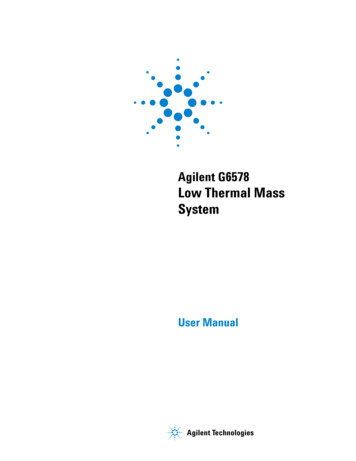
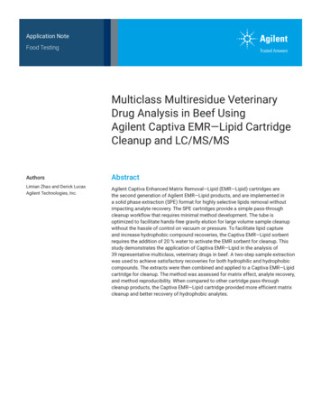
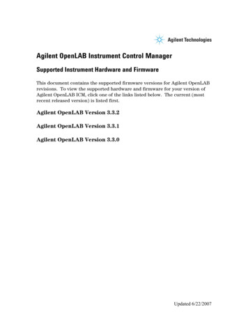
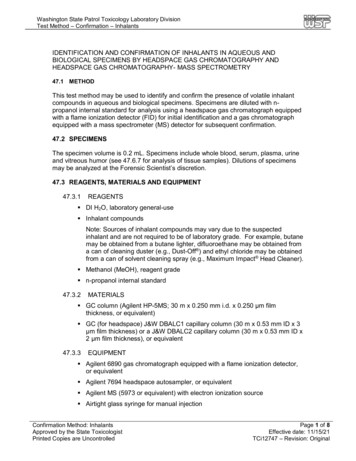
University at BuffaloShared InstrumentationLaboratories11. In the Valves tab, Valve #1 is the Gas Sampling Valve. Set up the Load Time and Inject Time(Fig. 2). This is the time for the gas sample to be loaded in the TCD and FID loops if you selectto automatically introduce the gas sample. If you select to manually inject the gas sample,this time doesn’t matter. Keep the Heater temperature at 150 C (max 225 C). 1 aJveIReadiness IiGC CalculatorsLoad Tme inn)Postionr-;ectTmejn;n)Ga,5-'!, V,JveNIA112Not.,,.aledNIAN/ ANIA#3Not.,,.aledNIAN/ ANIA114Not.,,.aledNIANIANIA#5Not.,,.aledNIAN/AN/ Am;Not.,,.aledNIAN/ ANIAIf]Not nstaledNIAN/ ANIA#8Not .,,.aledNIAN/ANIA.Vl/Jve BaxActualr{] Heater150'C150'CFigure 2. Edit the Valves tab12. In the Inlets tab, set up CAP SSL inlet and PPI inlet settings separately (Fig. 3 and Fig. 4)1) CAP SSL inlet (for FID gas line): Set Heater temperature at 250 C (max 300 C) Keep the Pressure value unchanged If split ratio 20:1, Total inlet flow Column flow (HP-5) x 20 Column flow (HP-5) Septum purge flow li l,Q, 1ISSL - Front pp - BackLOvenDetectorsEv entsSignalsXConfigurationReadinessmuGC CalculatorsISplit -Splitless InletSelect Liner. .A Liner has not been selected.Gas Saver:SetpointActual Heater:250 'C250'C Pressure:12071 psi12.1 psi66 mU min66mUmin3 ml/min3mUminTotal Flow: Septum Purge Flow:Septum Purge Flow Mode:Mode:20mUmin§ andardAfter: 2 rrun:)Split Ratio:20:1Split Flow 60mU minFigure 3. CAP SSL inlet settings (for FID gas line)3
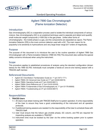
University at BuffaloShared InstrumentationLaboratories2) PPI inlet (for TCD gas line): Set Heat temperature at 250 C (max 300 C) Total inlet flow Column flow (HayeSep) Septum purge flow Keep Control Mode as Flow 111 1,20 OvenDetectorsEv entsXSignalsConfigurati onReadinessiGC CalculatorsSSL - Front PP - Back ]Purged Pocked I nletA Liner has not been selected.Select Liner. .SetpointActual['.l] Heater:250 'C250'C['.l] Flow:23 mUmin23mUminControl Mode:['.l] Septum Purge Flow:. I[ Row3 mU min3mUminFigure 4. PPI inlet settings (for TCD gas line)13. In the Columns tab, set up HP-5 column and HayeSep column separately (Fig. 5 and Fig. 6)1) HP-5 column (for FID gas line): Set the Column flow and keep the other settings unchanged Make Column flow Post Run flow Select “Constant Flow” modet1'\ i 1Ql ALS#ValvesSelectionInletsOven Detect orsEventsX1,SignalsConfigurationRe:adinesslaGC CalculatorsControl Model:t) OnSetpointActualFlow3 mUmin3 mUminPressure12.071 p 12.1 p Average Velocity43.715 an/sec(Initial): OminHoldup Time11438minHe @ 30 'C OvenOu: lvnbtent Pressure30 mx320µ,,x0.25µnIConstant RowPost Run: 3 mUminColLrm #1 ConfigurationI Change Column . 11 Calibrate Column. 11Lock Column.Figure 5. HP-5 column settings (for FID gas line)4
University at BuffaloShared InstrumentationLaboratories2) HayeSep column (for TCD gas line): Set the Column flow and keep the other settings unchanged Make Column flow Post Run flow Select “Constant Flow” mode'ALS ValvesOveni3Detectors EventsII SelectionXSignalsConfigurationIReadinessiGC CalculatorsCorool Mode0 0nSetpointActual20mUminFlow20mUmin222 p (htial): 0 rrinHe @ 30 'C OvenOu: "'1bent PressureUi nown1Constant RowPost Run: 20ml./minCoum #2 Corf,gcrationI Change C-Olumn. Irt, CLock Coiunvi.Figure 6. HayeSep column settings (for TCD gas line)14. In the Oven tab, set up the temperature ramp program Maximum Oven Temperature 290 C Equilibrium Time 0.5 min Post Run temperature 50 C or the starting temperature of the ramp programI 1: ---l(15020 --- ---- --- ---- --- --- --- --- ---- ------ O10 '14121618i3lO-Col.,m2 He: ml/,rin-Oven: C*20Run Time, minALS v, tvesO r-ijColumnsInlets DetectorsActualEventsX1,SignalsMaxunum Oven Temperature*.,.,fb Tme50Ran 1Ran 2 IiiGC CalculatorsHoid Tme'C(Iii.al)Equilibrabon TimeO.Smi"lReadinessVuRale30'CIConfigu ration'C/nw,,/ OvenTempOnSO 'C 101201014017290'C!!:I Override ColurM Max: 290 cPost Run: 50 "CPost Run Time· 0 mi1Figure 7. Oven temperature ramp program5
University at BuffaloShared InstrumentationLaboratories15. In the Detectors tab, set up FID (Front) and TCD (Back) settings, separately (Fig. 8 and Fig. 9)1) FID detector (Front): Set the Heater temperature at 300 C (max 300 C) Air flow 400 ml/min; H2 fuel flow 30 ml/min; Makeup flow (He) 25 ml/min Check “Constant Makeup and Fuel Flow”; Check “Flame”, iALSValvesFIO ·R-ont l ssGC Calculators·BadtlFID2pA0 FlomeActualSetpoint111 Heater:JOO'CJOO'C111 A,r Flowe400ml./mi,400ml./nw,111 H2Fuel Flow:30mllrni"I30mUnw,111 Makeup Flow: (He)25mL./mi,25mUrraiFIDSubtroct &om Signal.a (No hino)--' Column Compensation CLWVe 1'1Colu,m Compensation C.-ve :2Carrier Gas Flow ConectionColu,m Flowe (He)3mL./mi,t'.) Coll#M Fuel ConstantColl.WM Makeup Constant(o Constant Makeup and Fuel FlowFigure 8. FID detector (Front) settings2) TCD detector (Back): Set the Heater temperature at 300 C (max 300 C) Makeup flow (He) 5 ml/min, Constant Makeup Flow Reference flow Makeup flow Column flow (HayeSep) Check “Filament”' iALSValves0ColumnsInletsFID ·Front TCD · Back Ovon'PDetectors LEventsXConfigurationReadinessGC 'C300'CSubtract from Signal:Q( Nothing)ColUJM Compensation Curve #1 Reference Flow:25mUml OmUm05ml./nw15mUmMakeup Flow: (He)CUITVl "1a1 ec;,v Coll.nm Co,npensation Curve #2.C@ Constant Makeup Flow0 FilamentEJ Negative Polarity1 (25 µV)Figure 9. TCD detector (Back) settings6
University at BuffaloShared InstrumentationLaboratories16. In the Events tab, set Time 0.1 min, Event Type Valve, Position Valve 1, Setpoint On(Fig. 10). This setting makes the GSV to open/close in 0.1 min after the test is started.'ALS ValvH01)InletsColumnsOv,n0t: l I .XConfigurationIReadinHsRuntime Events1 · v.- ·-Even Tw,eTmefrWI)[rl]liiilGC Calculatorsv. , I I1- 1 1Figure 10. Events settings17. In the Signals tab, set up FID and TCD signals separately (Fig. 11)#1: Front Signal (FID): select 50 Hz / 0.004 min, check Save to record data#2: Back Signal (TCD): select 5 Hz / 0.04 min, check Save to record dataOvenDualXDetectorsConfigurationSignal SourceData Rate / Min Peak WidthF#1: Front Signal (FID)B#2: Back Signal (TCD).B#3: Diagnostics: Test Plot,. lso Hz / 0.004 minB#4: Diagnostics: Test Plot. [SO Hz / 0.004 min50 Hz / 0.004 minS Hz / 0.04 minReadiness.ZeroGC CalculatorsSave I Hide Dual Injection Signal Assignments ISignal Evert TableDelete[ Signal Sourcen me. minSignal EventEventsFigure 11. Signals settings18. Click Apply and then click Ok to close the Setup Method screen19. Click Save Current Method in the second line of the software to save the changes (Fig. 12)\01-28-2020\jiquid injection.M.Sequen cesINMffil;H,NFigure 12. Save Current Method icon7
University at BuffaloShared InstrumentationLaboratories1.3Start the Measurement20. If you wish to manually run the samples one by one:1) On the top line of the software, click Run Control Run Method2) The status shows “Run in Progress/Waiting for Injection” in purple3) Walk to the GC and manually inject your gas sample into the inlet4) Press the Start button on the GC front panel5) After 0.1 min, you will hear the gas sampling valve is closed6) The status shows “Run in Progress/Data Acquisition” in blue as well as the elapsed time21. If you wish to automatically introduce the samples and run in sequence:1) On the top line of the software, click Sequence Sequence Table2) A “Sequence Table: 7890GC Gas Sampling” screen will pop out (Fig. 13)Sequence Table: 7890GC Gas Sampling.u:2c -- Te,15-2T eforGCUWW\O.--Souceo,Loc-.:]h.MelhodT e forGCU'ari'\g ,. MethodT e forGCtrainng ,. Melhodv.,.Figure 13. “Sequence Table: 7890GC Gas Sampling” screen3) Fill the Sample Name for each sample4) Select the desired method in the Method Name drop listNOTE: If the desired method is not included in the Method Name drop list, click the“Browse Method” icon to open the desired method (Fig. 14), then you can find it in theMethod Name drop listMethod NameTemplate for GC trainingFigure 14. Browse Method icon8
University at BuffaloShared InstrumentationLaboratories5) Keep the other parameters as below: Injector Location Front; Injection Source AsMethod; Inj/Loc 1; Sample Type Sample6) Click Apply and then click OK to close the Sequence Table screen7) On the top line of the software, click File Save As Sequence Template8) A “Save Sequence as: 7890GC Gas Sampling” screen will pop out (Fig. 15)Save Seque nce as: 7890GC Gas mplingFoidef :c:\. .\2\seq.Jence'be,fie :T.-.,late for GC tranng .Sl c, CHEM322 SEOUENCECJ 01-29-2020CJ 05-02-2019CJ ll ro-2019CJ - 2 019Save fie as type:c-fves:I5equence,.s li!l c: W.OS [ Netwo,LIFigure 15. “Save Sequence as: 7890GC Gas Sampling” screen9) In the file browser, find the directory of your sequence “C:\Chem32\2\Sequence\[YourName]”, and create a new subfolder using the current date10) On the right side of the “Save Sequence as: 7890GC Gas Sampling” screen, locate the newsubfolder you have just created and double-click it11) On the left side of the “Save Sequence as: 7890GC Gas Sampling” screen, input the nameof your sequence (e.g., xxxxxx.S) in the File Name field12) Click OK to close the “Save Sequence as: 7890GC Gas Sampling” screen13) The sequence directory will appear in the second line of the software (Fig. 16). It is nowloaded as the current sequence.7890GC Gas SomFile RunControlInstrument[ M.thods4!J QTerrc,iate for GC tr., .MR eadyFigure 16. Display the current sequence9
University at BuffaloShared InstrumentationLaboratories14) On the top line of the software, click Run Control Run Sequence15) A “Waiting for Ready” screen will pop out (Fig. 17)Sta rt Run: 7890GC Gas Sa mplingWaiting for Ready .Press Start Run to Override2tart Run bort RunFigure 17. Waiting for Ready screen16) The status shows “Sequence Running/Data Acquisition” in blue17) The GSV opens at 0.1 min to start loading the gas sample automatically. It willautomatically close after a certain period of time to start the test run. This time durationis determined by your method setting for Load Time and Inject Time in the Valves tab.1.4Post-run Procedures22. After a test run is completed, a .pdf report will automatically pop out23. The data will be automatically stored in the folder of “C:\Chem32\2\Data”. You need tocreate a new subfolder with directory “C:\Chem32\2\Data\[Your Name]”, move the newlyreported data into your subfolder, and rename it.24. After all the test runs are completed, close the “7890GC Gas Sampling (online)” software25. Walk to the GC, on the GC front panel:1)2)3)4)5)6)Press the “Front Inlet” buttonUse the downward arrow button to select “Pressure”Press the “Off/On” button to turn it OFFPress the “Back Inlet” buttonUse the downward arrow button to select “Total flow”Press the “Off/On” button to turn it OFFNOTE: You can double-click the icon “7890GC Gas Sampling (offline)” on the right side of Desktopto open the offline software to view and analyze the data in the “Data Analysis” tab.10
University at Buffalo"%2.0 Shared InstrumentationLaboratoriesSpecificationsSystem components: Thermal Conductivity Detector (TCD) at the back Flame Ionization Detector (FID) at the front Gas sampling valve with 0.5 ml TCD loop and 0.25 ml FID loop PPI inlet (purged packed inlet) for TCD gas line CAP SSL inlet (capillary split/splitless inlet) for FID gas line HayeSep packed column for TCD gas line HP-5 capillary column for FID gas line OpenLAB CDS ChemStation softwareCarrier gas: heliumElectronic pneumatic control (EPC) modulesMaximum oven temperature: 290 CThermal Conductivity Detector (TCD): Linear dynamic range: 105 5% Maximum temperature: 300 C Standard EPC for 2 gases (He, H2, or N2 matched to carrier gas type) Make-up gas: 0 to 12 ml/min Reference gas: 0 to 100 ml/minFlame Ionization Detector (FID): Linear dynamic range: 107 10% Maximum temperature: 300 C Standard EPC for 3 gases (air, H2, make-up gas) Air: 0 to 800 ml/min H2: 0 to 100 ml/min Make-up gas: 0 to 100 ml/minHayeSep packed column: Temperature range: -60 C to 290 C Feature: 3 m x 1/8 inch x 2 mm; packed with HayeSep DB 80-100 Mesh In: PPI inlet; Out: TCD detector at the backHP-5 capillary column: Temperature range: -60 C to 325 C Feature: 30 m x 320 µm x 0.25 µm In: CAP SSL inlet; Out: FID detector at the front11
University at Buffalo"%3.0Shared InstrumentationLaboratoriesUser RequirementsThe Agilent 7890B GC with GSV must be used by authorized personnel only. All authorized usersare expected to read and understand this SOP and follow the operation instructions carefully. Nounauthorized user may operate this GC with GSV unless accompanied by an authorized user. Allvisitors must be briefed on proper safety protocol and must wear appropriate personal protectiveequipment. To become an authorized user, one must:1.2.3.4.5.6.7.4.0Complete the New User Scope of Work FormRead and sign the Materials Characterization Laboratory (MCL) Governance DocumentComplete Environment, Health & Safety (EH&S) training classTake the basic MCL orientation sessionReceive training on the operation of this GC with GSV by the MCL staffRead and fully understand this SOPSign the training certificate form and receive the Google Calendar for online reservationGeneral Safety4.1 Required Personal Protective EquipmentUsers must wear lab coats, safety glasses, and gloves. Shorts, open-toed shoes, high heels,and skirts, are forbidden.4.2 Emergency Procedures and ContactsFor non-life threatening emergencies: notify the MCL facility manager and your PIimmediately.Facility manager: Zongmin (Shirley) Bei, Ph.D.Office: 109B Furnas Hall, Tel: (716) 645-5165, Cell: (585) 354-5623Email: zongminb@buffalo.eduor for police / ambulance, call 645-2222In case of fire or other life threatening emergency: Exit the laboratory through anemergency exit door. Pull one of the fire alarms located in the main hallway. Dial campuspolice / ambulance at 645-2222.4.3 Power outage: If there is a power outage, turn off the GC with GSV system according tothe shutdown procedure to avoid a hazardous situation when power is restored. If thereis an emergency, leave the MCL immediately and either return after emergency to shutdown the GC with GSV system or contact the facility manager.4.4 University after hours laboratory use policyNo working alone, use the buddy system!12
University at Buffalo"%Shared InstrumentationLaboratories#Revised by1 Zongmin (Shirley) Bei2345Date01/29/2020ModificationDocument initial release13
Conductivity Detector (TCD) at the back and Flame Ionization Detector (FID) at the front, are dedicated for detecting most permanent gases excluding the carrier gas and most organic compounds (e.g., hydrocarbons), respectively. 1.0 Safety Precautions General Laboratory Precautions Avoid leaks in the carrier gas lines.