Transcription
SERIES 401, 402, 403 storefrontInstallation InstructionsPart NO. Y001April 29 2020
Series 401,402, & 403 Installation InstructionsTABLE OF CONTENTSSECTIONPAGEI.General Notes . . . 3II.Parts Identification Charts . . 4-30III.A.S401 Parts IdentificationB.S402 Parts IdentificationC.S403 Parts IdentificationFabrication and AssemblyA.Screw Spline Fabrication . . . . . 31-36B.Shear Block Fabrication . . . . . . 37-45C.Corner Fabrication . . . . 46-47D.Expansion Mullions . . . . 48E.Steel Reinforcing . . . . . 49F. High Side Lite Bases . . . . 50-53G. Adjustable Height Side Lite Base . . . . 54-58IV.InstallationA.Door Frame Installation . .59-60B.Sill Flashing Installation . . . . . 61-64C. Screw Spline and Shear Block Systems Installation . . . . 65-70D. High Side Lite Base Installation. . . . .71-74V.E.Adjustable Height Side Lite Base Installation . . . 75-81F.Can System Preparation/Installation . 82-84Glazing . . . . . . 85-94V: A. Water Deflector InstallationV: B. Pocket Dimensions and Glass Size FormulasV: C. Outside GlazingV: D.Inside GlazingV: E.Window Adaptors Preps/InstallationV: F.1” Pocket Reducers for ¼” and ½” GlassSee Additional Supplements:Dorma RTS 88 Concealed Overhead Closers . .Y013Door, Door Glass and Hardware .Y015Minimizing CondensationNote: Please reference EFCO's "Understanding Condensation" brochure which can be obtained through your EFCO representative.Condensation will form on any surface when unfavorable conditions (interior temperature and relative humidity and exteriortemperature) are present. When the formation of excessive condensation is a concern, it is highly recommended that a designprofessional is utilized to perform an analysis of the shop drawings to recommend the best possible installation methods. Pleasecontact your EFCO representative for information on EFCO's Thermal Analysis Services.Many current installation practices lead to an increase in the possibility of the formation of condensation. Though not allinclusive, the list of examples below illustrates conditions under which condensation is likely to occur:1. Bridging system thermal break with non-thermally broken metal flashing or lintels that are exposed to theexteriorSystem exposure to cold air cavitiesInterior relative humidity levels not maintained at recommended levels, see EFCO’s “UnderstandingCondensation” brochure4. Inadequate separation between system and surrounding condition at perimeter5. Product combinations during the shop drawing stage that result in bridging thermal breaksof one or all products involved2.3.EFCO CORPORATIONPART NO. Y001Page 2 of 94
Series 401,402, & 403 Installation InstructionsSECTION I: General NotesSERIES 401 - 1 3/4" x 4 1/2" - 1/4" GLAZINGSERIES 402 - 2" x 4 1/2" - 1" GLAZINGSERIES 403 - 2" x 4 1/2" - 1" GLAZING (THERMAL)1) Check shop drawings, installation instructions, and glazing instructions tobecome thoroughly familiar with the project. The shop drawings takeprecedence for extrusions and details on the project. THESE INSTALLATIONINSTRUCTIONS ARE OF A GENERAL NATURE AND COVER THE MOSTCOMMON CONDITIONS AND SITUATIONS.2) Check all of the materials upon arrival and be sure you have everythingrequired to begin installation. (See Section II "PARTS IDENTIFICATION")3) All work should start from bench marks and/or column center lines asestablished by the architectural drawings and the general contractor. Checkconstruction for compliance with the contract documents.4) NOTE: Sealants must be compatible with all surfaces. Consult with the sealantmanufacturer for recommendations regarding compatibility and adhesion.5) All materials are to be installed plumb, level, and true.6) Protect materials after erection. Cement, plaster, alkaline solutions, and acidbased materials can be harmful to the finish. Masonry runoff may leach harmfulacids onto the storefront. This situation must also be taken into consideration atinstallation.7) Clean aluminum surfaces with a mild detergent and water. No abrasive agentshall be used.EFCO CORPORATIONPART NO. Y001Page 3 of 94
Series 401,402, & 403 Installation InstructionsSECTION II: A. S401 PARTS IDENTIFICATIONVertical Parts:Drawings on this page are not to scale.910286819103910491179120Tubular VerticalMullionFor L100 Steel Reinf.Tubular VerticalMullionFemale ExpansionMullionUse W/9104Male ExpansionMullionUse W/9103Use W104Weathering¾” x 4 ½”System Adaptor orDoor JambOpen Back VerticalUse W/9121,9122 or9146912191229163916491658557Open Back AdaptorUse W/9120,9147,9148 or 9171Open Back Adaptorat Butt HingeUse W/9120-slide fit-Splayed MullionFemale PortionUse W/9164 or 9165Use W104Weathering0 to 15 Splayed Male PortionUse W/9163Use W104Weathering15 to 30 Splayed MullionMale portionUse W/9163Use W104Weathering135 MullionFixedShear Block only86968697869892979115* 90 Corner MullionHalfTwo for 180 Fits W/8697 for 90 * 90 Corner MullionHalfTwo for 180 Fits W/8696 for 90 Fits W/8698 for 3way* 3-Way CornerMullion HalfFits W/8697 for3-wayFor Shear Block only* 90 CornerMullion HalfFits W/8696,8967 &8698* (4” x 4 ½”)Vertical Mullion HalfSelf-Mating only1G144 ½” DeepAdjustable Side LiteBase VerticalW/BRK. MTL.Use W/1G13 Horiz.EFCO CORPORATIONPART NO. Y001Page 4 of 94
Series 401,402, & 403 Installation InstructionsSECTION II: A. S401 PARTS IDENTIFICATIONHorizontal Parts:91484 ½” x 4 ½” SideLite BaseUse W/9129Glass Stop.Use W/9121,9146 or 91491G144 ½” DeepAdjustable SideLite BaseVertical W/BRK.MTL.Use W/1G13Horizontal91319137OBSOLETEOBSOLETE91494 ½” x 4 ½” SideLite Anchor Base9128IntermediateHorizontalUse W/9129Glass StopEFCO CORPORATIONDrawings on this page are not to scale.E178Frame ReceptorClosureUse W/1510Use WA04Weathering91602 9/16” DeepAdjustable SideLite Base Horiz.W/ BRK. MTL.Use W/9161VerticalUse (2) 9133Glass StopsUse W104Weathering1510Frame ReceptorUse E178ClosureUse WA04Weathering91612 9/16” DeepAdjustable SideLite BaseVertical W/BRK.MTL.Use W/ 9160Horizontal1G134 ½” DeepAdjustable SideLite BaseHorizontalW/BRK. MTL.Use W 1G14VerticalUse (2) 9129Glass StopsUse W104Weathering9145HeadUse W/9146Adaptor9147Open Back Horizontalw/ Sill Use W/9129Glass Stop Use W/9121 Glz. Adaptor orFS92 / 9146 FillerPART NO. Y001Page 5 of 94
Series 401,402, & 403 Installation InstructionsSECTION II: A. S401 PARTS IDENTIFICATIONDoor Frame Parts:Drawings on this page are not to scale.91099108911291719134Single ActingDoor jambUse W138WeatheringDouble ActingDoor Jamb1/8” WallWeatheringSingle ActingDoor JambUse W138Single ActingDoor Jamb forScrew SplineSide LitesUse 9121Glazing AdaptorUse W138WeatheringSingle ActingTransom BarUse W/ 9123Glass StopUse W138Weathering912791749129912391339132Dual Actingtransom BarUse W/ 9123Glass StopScrew SplineDoor HeaderUse W/ 9123 ¼”Glass StopUse W138WeatheringGlass Stop UseW/ 9128, 9147,9148 & 1G13Removable Stop¼” Glazing atTransom BarRemovable Stop¼” Glazing at9160, 9131 &9138 Side Base,or 9150 App.GlazingSide Lite BaseAdaptor FootUse W/ 9131 &913791389146FS92L131FV589149OBSOLETEStock LengthOpen Back FillerUse W/ 9120,9145 or 9147( see FS92 )3” PerimeterAdaptor ClipUse W/ 401Open BackFrames120” LightweightPVC PerimeterAdaptorUse W/ 9120,9145 or 91473” PerimeterPVC AdaptorClipUse W/ 9120,9145 or 91474 ½” x 4 ½” SideLite Anchor Base91509151915291549155Applied FixedSashUse W/ 9133Glass Stop for¼” GlassSnap In PocketFillerUse W/ 401SystemSnap-in DoorStopUse W/ 401SystemUse W138WeatheringApplied DoorStopUse W/ 9155Use W138WeatheringApplied DoorStop CoverUse W/ 9154EFCO CORPORATIONPART NO. Y0019156¼” GlazingAdaptor atTransomUse W/ 9109 &910Page 6 of 94
Series 401,402, & 403 Installation InstructionsSECTION II: A. S401 PARTS IDENTIFICATIONDoor Frame Parts:Drawings on this page are not to scale.9144915344374438Applied ¾” DoorStopApplied DoorStopApplied 5/8”Stop Used AtDoor HeaderOnlyMates W/91555/8” Snap-inDoor Stop atDoor HeaderOnlyUsed W/1 ¾”DoorEFCO CORPORATIONPART NO. Y001Page 7 of 94
Series 401,402, & 403 Installation InstructionsSECTION II: A. S401 PARTS IDENTIFICATIONShear Blocks & Clips:Drawings on this page are not to scale.K120K122K123K124K126( CLR & BRZ )Door HeaderShear Block Pkg.Screws IncludedHorizontalIntermediateShear Block Pkg.Screws IncludedHigh Side LiteShear Block Pkg.Screws Included( CLR. & BRZ. )Threshold ClipPkg.O.P. Butt HScrews IncludedC.O.C.Threshold ClipPkg.Screws IncludedK153 (CLR)K154(BRZ)Threshold ClipPackage forConc. Rod PanicScrews IncludedSill Flashing & End Caps:K449F098K29399479957End Cap Pkg. for#9957 SillFlashing3” Flashing Clip2 Per D.L.O.Use W/ 9957Sill FlashingSplice ( STD.)HighPerformance LiteSill FlashingStandard HighPerformance SillFlashingUse K449 EndCapGlass Setting Blocks:HN80K166H161H160Inside GlazedHorizontalSetting BlockDoor TransomSetting BlockPkg.Use W/9123 ¼”Glass StopHigh SideliteBase SettingBlock Pkg.HorizontalSetting BlockPkg.EFCO CORPORATIONPART NO. Y001Page 8 of 94
Series 401,402, & 403 Installation InstructionsSECTION II: A. S401 PARTS IDENTIFICATIONS401 Drill Jigs:Drawings on this page are not to scale.DJ01DJ03H700H701H382Shear Block DrillFixture(Head Members)Shear Block DrillFixture( Horizontals toShear Blocks )Economy DrillGuides( Shear Block toVertical )Economy DrillGuides( Screw SplineApplication )Shear Block /Screw SplineDrill Fixture( At Verticals )Steel Reinforcing:L100L101Tubular MullReinforcing SteelUse W/ 9102,9108, 9109,9112 & 9120Expansion MullReinforcing SteelUse W/ 9103 &9104Fasteners:M109STK0S129S100M100S123Threshold ClipScrew#12-24 x 3/8”FH-MSAdjustable SideLite Base Vert. toMull AttachmentScrew 4 ½”Deep Base#8-18 x ¾” PHSMS 410 TEK/2Frame SplineAttachmentScrew#10-16 x SQSMSType 25Zinc ChromateShear BlockAttachmentScrew#8 x 1 ¾” PHSMS( CLR )High Side LiteBase ShearBlock Screw#12 x ¾” FHSMS-FS109High Side LiteBase ShearBlock Screw#8 x 2 ½” FHSMSEFCO CORPORATIONS110 (CLR)S113 (BRZ)Horizontal to ShearBlock Screw#12 x ½” FH-MS“F”M108( BRZ )Frame to OffsetPivot Screw#12 x ¾” FHSMS-FSTT7STU5Adjustable SideLite BaseVerticalAttachment#10-12 x 1” PHSMSAdjustable SideLite Vert. to MullAttachmentScrew 2 ½”Deep Base#8-15 x 2” PHSMSPART NO. Y001S108Screwspline T hold - 9951#8-18 X 1 SL-HW-SMSZC B-LP .25Page 9 of 94
Series 401,402, & 403 Installation InstructionsSECTION II: A. S401 PARTS IDENTIFICATIONGasket:Drawings on this page are not to scale.W165W166W199W138Glazing Gasketfor UndersizedGlassFor 3/16”Glazing UseW164 Interior &W165 ExteriorGlazing Gasketfor OversizedGlass5/16”-3/8” Infill401StandardGlazing Gasket¼” Infill 401StandardWeather Seal @Door StopsWA04W104HN54StandardWeather Seal @SubframesWeather SealGasketUse W/Expansion Mulls,@ Variable Mullsor Adj. HeightSide Lite Bases¼” AntiwalkBlock401 OnlyEFCO CORPORATIONPART NO. Y001Page 10 of 94
Series 401,402, & 403 Installation InstructionsSECTION II: B. S402 PARTS IDENTIFICATIONVertical Parts:Drawings on this page are not to scale.92049202Vertical Mullion9203920492209212FemaleExpansionMullionUse W/ 9204Male ExpansionMullionUse W/ 9203Use W104WeatheringOpen Back VertUse 9221, 9222,or 9246/FS93Peri. AdpatorOpen BackVertical 1/8” Wallfor L102 SteelUse 9221, 9222or 9246/FS93PerimeterAdaptor9223Heavy-DutyOpen BackMullionUse W/ 9221 or9222Use pen BackGlazing AdaptorUse W/ 9220,9223, 9247 or9248Open BackGlazing Adaptorat Butt HingeUse W/ 9220 or92234” x 4 ½” TubularDoor Jamb /Header135 MullionFixedShear BlockOnly90 CornerMullion HalfTwo for 180 Fits W/ 9244 for90 9296924492969297Corner MullionHalfFits W/ 9224 for90 Fits W/ 9296 for3 Way3-Way CornerMullion HalfFits W/ 9244 for3-Way90 CornerMullion HalfFits W/ 9224,9244 & 9296Self-Mating for aCoverEFCO CORPORATIONPART NO. Y001Page 11 of 94
Series 401,402, & 403 Installation InstructionsSECTION II: B. S402 PARTS IDENTIFICATIONHorizontal Parts:Drawings on this page are not to scale.9236924592479248Tubular Side LiteHorizontalUse W/ 9229Glass StopHeadUse W/ 9246AdaptorOpen Back Sillor HorizontalUse W/ 9229Glass Stop9246 adaptors4 ½” x 4 ½” SideLite BaseUse W/ 9229Glass Stop9246 or 9221Adaptors or Use9149 Anchor926891499270Open Back Headfor Round TopsUse W/ 9269Glass StopFS93 Peri. Adpt.4 ½” x 4 ½”Side Lite AnchorBaseUse W/ 9248Heavy-DutyTubularHorizontalUse W/ 9271Glass StopUse K358 ShearBlock PKG.9160Adjustable SideLite BaseHorizontal W/BRK. MTL.Use W/ 9161Use 9253 GlassStopUse W104Weathering92318” HorizontalSelf-MatingUse (2) K129Shear BlockUse RemovableStop HorizontalsAbove & BelowEFCO CORPORATIONPART NO. Y001Page 12 of 94
Series 401,402, & 403 Installation InstructionsSECTION II: B. S402 PARTS IDENTIFICATIONDoor Frame Parts:Drawings on this page are not to scale.9234922792749208Single ActingTransom BarUse W/ 9123 for1” Glass StopUse W138WeatheringDual ActingTransom BarUse W/ 9123 for1” GlassSingle ActingScrew SplineTransom BarUse W/ 9123 –¼” GlazingUse W/ 9253 –1” GlazingUse W138 GSKTDouble ActingDoor Jamb9209920992329254437691339123Single ActingDoor jambUse W138WeatheringSingle ActingDoor Jamb forScrew SplineSide LitesUse 9221Glazing AdaptorUse W138Weathering1” GlazingAdaptor atTransomUse W/ 9208 or92091” GlazingAdaptor atTransomRemovable StopUse W/ 9250 for1” AppliedGlazingRemovable Stop1” Glazing at2” x 4 ½”Transom Bars926992509229927192519253Removable Stopfor 9268 HeadOnly1” Glazing atRound Top HeadApplied FixedSashUse W/ 9133StopRemovable StopFor 1” GlazingUsed W/9236,9247,9248& 1G13Removable Stopfor 9270 H.D.Horizontal1” GlazingSnap-In PocketFiller for 1”GlazingNonthermalGlass Stop1” Glazing at9274 Transom &9160 / 9161 SideBaseEFCO CORPORATIONPART NO. Y001Page 13 of 94
Series 401,402, & 403 Installation InstructionsSECTION II: B. S402 PARTS IDENTIFICATIONMisc. Parts:Drawings on this page are not to scale.91611G131G149246FS93Adjustable SideLite BaseVertical W/ BRK.MTL.Use W/ 9160Adjustable SideLite BaseHorizontal W/BRK. MTL.Use 1G14Use 9229 GlassStopUse W104WeatheringAdjustable SideLite BaseVertical W/ BRK.MTL.Use W/ 1G13Stock LengthOpen Back FillerUse W/ 402 &403 Open BackFrames( See FS93 &K318 )3” PerimeterAdaptor ClipUse W/ 402 &403 Open BackFrames( See 9246 &K318 )K318L132FV59L1333” PerimeterAdaptor ClipPkg.Use Only W/9247 at Head /Sill( See 9246 &FS93 )120” LightweightPVC PerimeterAdaptorUse W/ 9220,9245 at Jamb &Head3” PerimeterPVC AdaptorClipUse W/ 9220,9245 at Jamb &Head120” LightweightPVC PerimeterAdaptorUse W/ 9247 atSillFV60926092613” PerimeterPVC AdaptorClipUse W/ 9247 atSillGlazing Adaptorfor ½” GlassIn 1” GlazingPocketGlazing Adaptorfor ¼” Glass in 1”Glazing PocketEFCO CORPORATIONPART NO. Y001Page 14 of 94
Series 401,402, & 403 Installation InstructionsSECTION II: B. S402 PARTS IDENTIFICATIONMisc. Parts:Drawings on this page are not to scale.993886431G15ShadowlineWindow AdaptorEqual LegUse W104WeatheringSystem IIWindow AdaptorEqual LegUse W104WeatheringHoriz. / Vert.Stack Adaptor4” Sightline1G691G688741Horiz. / Vert.Stack Adaptor2” SightlineHoriz. / Vert.Stack Adaptor2” sightline w/RevelHead / Sill CanS402 System2” Sightline8742874316C716C8NonremovableStopCan FillerRemovable StopCan FillerUse W/ 8744Glass Stop2-Part MullionHalf2-Part PerimeterInterior Half16C92-Part PerimeterExterior HalfEFCO CORPORATIONPART NO. Y001Page 15 of 94
Series 401,402, & 403 Installation InstructionsSECTION II: B. S402 PARTS IDENTIFICATIONSill Flashing & End CapsDrawings on this page are not to scale.994784331G85HighPerformanceLite Sill FlashingStandard HighPerformance SillFlashingUse K449 EndCapHighPerformanceSill Flashing W/Stool ClipUses K448 EndCapK449F098K293K292End Cap Pkg.for #8433 SillFlashing(1) FT34(2) STC73” Flashing Clip2 per DLOUse W/ 9957Sill FlashingSplice( STD.)Sill FlashingSplice( OPT.)K448HWD1End Cap Pkg.for1G64 , 1G65 &1G85(1) FT33(2) STC6Water Deflector@ Int. HorizontalEFCO CORPORATIONPART NO. Y001Page 16 of 94
Series 401,402, & 403 Installation InstructionsSECTION II: B. S402 PARTS IDENTIFICATIONShear Blocks & Drill JigsK124 (clr)K125 (brz)O.P. & ButtHingeScrews IncludedDrawing on this page are not to scaleK129 (clr)K130 (brz)K126C.O.C.Threshold ClipPkg.Screws IncludedK173HorizontalShear BlockPkg.Screws IncludedUse W/ 9236,9247 or 9248Header ShearBlockPkg.ScrewsIncludedK358KN92KN93H.D. HorizontalShear BlockPkg.Use W/ 9270Screws Included402 / 403 2Piece RolledHead ShearBlock Pkg.402 / 403 2Piece Horiz.Setting ChairPkg.K153 (clr)K154 (brz)Threshold ClipPkg. for Conc.Rod PanicScrews IncludedDJ01DJ02H700H702H381Shear BlockDrill Fixture(Head MembersTo ShearBlocks)Shear BlockDrill Fixture(Horizontals toShear Blocks)Economy DrillGuides(Shear Block toVertical)Economy DrillGuides(Screw SplineApplication)Shear Block /Screw SplineDrill Fixture(At Verticals)EFCO CORPORATIONPART NO. Y001Page 17 of 94
Series 401,402, & 403 Installation InstructionsSECTION II: B. S402 PARTS IDENTIFICATIONSetting Blocks & Steel:Drawings on this page are not to scale.HNA3HN92HNA4Transom SettingBlock1” GlazingInside GlazedHorizontal SettingBlockInside GlazedSetting Block at SillHN32H190K354Exterior GlazedSetting Block /Chair AssemblyPkg. at Sill2” Transom Bar &2 ½” Side LiteBase Setting BlockPkg.Using 9253 GlassStop1” Glass SettingBlock Pkg. for1G13 / 1G14 Adj.Side Lite BaseL100L101L102Tubular MullReinforcing SteelUse W/ 9208 &9209Expansion MullReinforcing SteelUse W/ 9203 &92048 GaugeReinforcing SteelUse W/ 9212EFCO CORPORATIONPART NO. Y001Page 18 of 94
Series 401,402, & 403 Installation InstructionsSECTION II:B. S402 PARTS IDENTIFICATIONFasteners:Drawings on this page are not to scaleS101 (clr)S103 (brz)STB9Horizontal toShear BlockScrew#12 ½” RHSMS “A”Horizontal toShear BlockScrew @ Head#12 ¾” FHSMS “A”S129S100Frame SplineAttachmentScrew( #10-16 x 1”SQ-SMS )Type 25Zinc ChromateShear BlockAttachmentScrew( #8 x 1 3/4”PH )STT7STU5M109AdjustableSide Lite BaseVerticalAttachment#10-12 x 1”PHSMSAdjustableSide Lite BaseVert. to MullAttachmentScrew 2 ½”Deep Base#8-15 x 2”PHSMSThreshold ClipScrew#12-24 x 3/8”PHMSM100 (clr)M108 (brz)Frame toOffset PivotScrew( #12-24 x ¾”F.H.M.S.)SFQ2STK0WindowAdaptor toFrameAttachmentScrewUse W/ 9935 &9936#8-18 x ½” FHSMSAdjustableSide Lite BaseVert. to MullAttachmentScrew 4 ½”Deep Base#8-18 x ¾”PHSMS 410TEK/2S108Screwspline T hold - 9951#8-18 X 1 SL-HW-SMSZC B-LP .25EFCO CORPORATIONPART NO. Y001Page 19 of 94
Series 401,402, & 403 Installation InstructionsSECTION II: B. S402 PARTS IDENTIFICATIONGasket:Drawings on this page are not to scale.W165W166W199W138Glazing Gasketfor UndersizedGlass¾” Infill @ 1”PocketGlazing Gasketfor OversizedGlass1 1/8” Infill @ 1”PocketStandardGlazing Gasket1” Infill @ 1”PocketStandardWeather Seal @Door StopsWA04W104HN52StandardWeather Seal @SubframesWeather SealGasketUse W/Expansion Mulls,@ Variable Mullsor Adj. HeightSide Lite Bases1/2” AntiwalkBlockEFCO CORPORATIONPART NO. Y001Page 20 of 94
Series 401,402, & 403 Installation InstructionsSECTION II: C. S403 PARTS IDENTIFICATIONVertical Parts:Drawings on this page are not to scale.932293239324931493159316StandardTubular VerticalMullionHeavy-DutyOpen BackMullionUse W/ 9246,9315 & 9314Extra HeavyDuty Open BackMullionUse W/ 9246,9315 & 9314Open BackAdaptorUse W/ 9320,9323, 9324,9347 or 1G80Open BackAdaptor at ButtHingeSlide Fit W/ 9320& 93230 to 15 Variable FemaleMullion HalfUse W/ 9317Use W104Gasket9318931793189320930993110 to 15 Variable MaleMullion HalfUse W/ 9316Use W104Gasket15 to 30 Variable MaleMullion Half UseW/ 9316Use W104GasketOpen BackVerticalUse W/ 9246,9315 or 9314Glazing AdaptorFemaleExpansionMullion for L101Steel ReinforcingUse W/ 9311Male ExpansionMullion for L101Steel ReinforcingUse W/ 9309Use W104WeatheringEFCO CORPORATIONPART NO. Y001Page 21 of 94
Series 401,402, & 403 Installation InstructionsSECTION II: C. S403 PARTS IDENTIFICATIONHorizontal Parts:Drawings on this page are not to scale.9305932693272G569305( 4” x 4 ½”)Sidelite BaseUse W/ 9229,9149, 9314 or9246( 4” x 4 ½”)Head orHorizontalUse W/ 9314 or9246Outside2-Way CornerMullion HalfFits W/ 9299 for3-WayMust Be ShearBlocked2G57Inside135 FixedMullion92999300930092979299E178151090 CornerMullion HalfTwo for 180 Fits W/ 9299 for90 90 CornerMullion HalfFits W/ 9299,9305 & 9300Self-Mating ForA Cover90 CornerMullion HalfTwo for 180 Fits W/ 9300 for90 Fits W/ 9305 for3-WayFrame ReceptorClosureUse W/ 1510Use WA04WeatheringFrame ReceptorUse E178ClosureUse WA04Weathering9336934593471G80Tubular Side LiteHorizontalUse 9229 GlassStopHeadUse W/ 9246Open BackSill/HorizontalUse 9229 GlassStopUse W/ 9246Adaptor or 9314Glazing AdaptorOutside92299149Removable Stopfor 1” GlazingUsed W/ 9326,9336, 9347,1G13 & 1G804 ½” x 4 ½” SideLite Base AnchorUse W/ 9326 &1G80EFCO CORPORATIONPART NO. Y0011G81Inside4 ½” x 4 ½” SideLite BaseUse 9229 GlassStopUse W/ 9149 or9246 Anchors or9314 GlazingAdaptorPage 22 of 94
Series 401,402, & 403 Installation InstructionsSECTION II: C. S403 PARTS IDENTIFICATIONDoor Frame Parts:Drawings on this page are not to scale.9234922792749208Single ActingTransom BarUse W/ 9123 For1” GlassUse W138WeatheringDual ActingTransom BarUse W/ 9123 For1” GlassSingle ActingScrew Spline Transom BarUse W/ 9123 - 1/4” Glass, W/9253 – 1” GlassUse W138 WeatheringDouble ActingDoor Jamb9209920992329263913391239269Single ActingDoor JambUse W138WeatheringSingle ActingDoor Jamb forScrew SplineSide LitesUse W/ 9314Glazing AdaptorUse W138Weathering4” x 4 ½” TubularDoor Jamb /HeaderRemovable StopUse W/ 9250 For1” AppliedGlazingRemovable Stop1” Glazing at 2” x4 ½” TransomBarsRemovable Stopfor 9268 HeadOnly1” Glazing atRound Top Head925093519253437692549257Applied FixedSashUse W/ 9133StopSnap-in PocketFillerFor 1” GlazingThermalGlass Stop1” Glazing at9274 Transom1” GlazingAdaptor atTransom1” GlazingAdaptor atTransomUse W/ 9208 or9209Snap-In Door Stop in1” Glazing PocketUse W138 Gasket91549155935593564441Applied DoorStopUse W/ 9155Use W138WeatheringApplied DoorStop CoverUse W/ 9154Snap In DoorStop Used With2” DoorSnap In Door Stop UsedWith 2” Door. This StopTo Be Used at ShallowPocket Jambs Only. Use9355 at Deep Pockets5/8” Snap InDoor Stop Usedat Door HeadersOnly. Used W/2”DoorEFCO CORPORATIONPART NO. Y001Page 23 of 94
Series 401,402, & 403 Installation InstructionsSECTION II: C. S403 PARTS IDENTIFICATIONMisc. Parts:Drawings on this page are not to scale.1G131G144420FU99Adjustable SideLite BaseHorizontal W/BRK. MTL.Use W/ 1G14Use 9229 GlassStopUse W104WeatheringAdjustable SideLite BaseVertical W/ BRK.MTL.Use W/ 1G13Stock LengthOpen Back FillerOpen BackFrames(See FU99)3” PerimeterAdaptor ClipOpen BackFrames(See 4420)L132FV5992609261120” LightweightPVC PerimeterAdaptorUse W/ 9320,9345 & 93473” PerimeterPVC AdaptorClipUse W/ 9320,9345 & 9347Glazing AdaptorFor ½” Glass in1” GlazingPocketGlazing Adaptorfor ¼” Glass in 1”Glazing Pocket99388643ShadowlineWindow AdaptorEqual LegUse W104WeatheringSystem IIWindow AdaptorEqual LegUse W104Weathering1G151G691G68Horiz. / Vert.Stack Adaptor4” SightlineHoriz. / Vert.Stack Adaptor2” SightlineHoriz. / Vert.Stack Adaptor2” SightlineW/ RevelEFCO CORPORATIONPART NO. Y001Page 24 of 94
Series 401,402, & 403 Installation InstructionsSECTION II: C. S403 PARTS IDENTIFICATIONMisc. Parts:Drawings on this page are not to scale.16C716C816C92-Part MullionHalf2-Part PerimeterInterior Half2-Part PerimeterExterior HalfL100Tubular MullReinforcingSteelUse W/ 9208 &9209EFCO CORPORATIONPART NO. Y001Page 25 of 94
Series 401,402, & 403 Installation InstructionsSECTION II: C. S403 PARTS IDENTIFICATIONSill Flashing & End Caps:Drawings on this page are not to scale.1G641G651G85HighPerformanceSill FlashingUse F098 ClipHighPerformanceSill FlashingHighPerformanceSill FlashingW/ Stool ClipUse K448 EndCapF098K448K293HWD13” FlashingClip2 per DLOUse W/1G64End Cap Pkg.for 1G64, 1G65& 1G85.(1)FT33(2)STC6Sill FlashingSplice(STD.)WaterDeflector @Int. HorizontalEFCO CORPORATIONPART NO. Y001Page 26 of 94
Series 401,402, & 403 Installation InstructionsSECTION II: C. S403 PARTS IDENTIFICATIONShear Blocks & Drill Jigs:K129 (clr)K130 (brz)Header ShearBlock Pkg.Screws IncludedDrawings on this page are not to scale.K172KN92Horizontal ShearBlock Pkg.Screws IncludedUse W/ 9336,9347 & 1G80402 / 403 2-PieceRolled HeadShear BlockPackageK124 (clr)K125 (brz)K153 (clr)K154 (brz)Threshold ClipPkg.O.P. & Butt H.Screws IncludedThreshold ClipPkg. for Conc.Rod PanicScrews IncludedDJ01DJ02H700H702Shear Block DrillFixture(Head Membersto Shear Blocks)Shear Block DrillFixture(Horizontals toShear Blocks)Economy DrillGuides(Shear Block toVertical)Economy DrillGuides(Screw SplineApplication)H381Shear Block /Screw Spline DrillFixture(At Verticals)EFCO CORPORATIONPART NO. Y001Page 27 of 94
Series 401,402, & 403 Installation InstructionsSECTION II: C. S403 PARTS IDENTIFICATIONSetting Blocks:Drawings on this page are not to scale.HNA3HN32HN92TransomSetting Block1” GlazingExterior GlazedSetting Block /Chair AssemblyPkg. at Sill &Horiz.Inside GlazedHorizontalSetting BlockHNA4H190K354Inside GlazedSetting BlockAt SillTransomSetting BlockPkg.Using 9253Glass Stop1” GlassSetting BlockPkg. for1G13/1G14Adj. Side LiteBaseKN93402 / 4032-PieceHorizontalSetting ChairPackageEFCO CORPORATIONPART NO. Y001Page 28 of 94
Series 401,402, & 403 Installation InstructionsSECTION II: C. S403 PARTS IDENTIFICATIONFasteners:STB9Horizontal toShear BlockScrew#12 ½”-RHSMS “A”Drawings on this page are not to scale.S101 (clr)S103 (brz)Horizontal toShear BlockScrew @ Head#12 3/4” FHSMS “A”STT7STU5M109AdjustableSide Lite BaseVerticalAttachment#10-12 x 1”PHSMSAdjustableSide Lite BaseVert. to MullAttachmentScrew 2 ½”Deep Base#8-15 x 2”PHMSThreshold ClipScrew#12-24 x 3/8”PHMSSTK0SFQ2S129S100AdjustableSide Lite BaseVert. to MullAttachmentScrew 4 ½”Deep Base#8-18 x ¾”PHSMS 410TEK/2WindowAdaptor toFrameAttachmentScrew.Use W/9935 &9936#8-18 x 1/2”FH-SMSFrame SplineAttachmentScrew#10-16 x 1”SQ-SMS.Type 25Zinc ChromateShear BlockAttachmentScrew#8 x 1 ¾” P.H.M100 (clr)M108 (brz)Frame toOffset PivotScrew#12-24 x ¾”F.H.M.S.S108Screwspline T hold - 9951#8-18 X 1 SL-HW-SMSZC B-LP .25EFCO CORPORATIONPART NO. Y001Page 29 of 94
Series 401,402, & 403 Installation InstructionsSection II: C. S403 PARTS IDENTIFICATIONGaskets & Antiwalk Block:Drawings on this page are not to Scale.W165W166W199W138GlazingGasket forUndersizedGlass¾” Infill @ 1”PocketGlazingGasket forOversizedGlass1 1/8” Infill @1” PocketStandardGlazingGasket1” Infill @ 1”PocketStandardWeather Seal@ Door StopsWA04W104StandardWeather Seal@ SubframesWeather SealGasketUse W/ExpansionMulls, @Variable Mullsor Adj. HeightSide LiteBasesHN50HN523/8” AntiwalkBlock9322 VerticalOnly1/2” AntiwalkBlock402 & 403Except 9322EFCO CORPORATIONPART NO. Y001Page 30 of 94
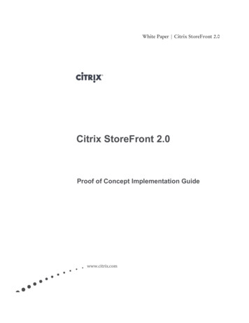
Series 401,402, & 403 Installation InstructionsSECTION III: A. SCREW SPLINE FABRICATIONThe screw spline system is a fabrication and erection method thatpermits the preassembly of single units in the shop or at the job site.These units are then erected by mating the male mullion with thefemale mullion counterpart.When an entrance is required, screw spline joinery may be used withthe screw spline door jambs only. Otherwise, shear block joinerymust be used to attach the side lite horizontals.NOTE)DUE TO THE SCREW TENSIONS REQUIRED FOR CORRECTINSTALLATION, IT WILL BE NECESSARY TO 'WAX' THE FRAMEASSEMBLY SCREWS TO PREVENT GALLING AND BREAKAGE.STEP 1) Measure the opening to determine the cut length of theframe components.NOTE: Allow minimum 1/2" shim and caulk space around perimeter.NOTE: Allow extra clearances, if necessary, to accommodate buildingtolerances and building movement.NOTE: Consult A.D.A. requirements to verify compliance.STEP 2) Cut the verticals to frame size.NOTE: Verticals must run through.If the opening has an entrance, see the appropriate frame anddoor fabrication installation sheets.NOTE: Door jambs run to the floor and are cut longer than otherverticals.STEP 3) Drill holes for assembly screws on vertical members.(See Fig. # 5 page 35).NOTE: Drill jigs are available.See pages 9, 17, and 27 of the parts identification section.STEP 4) Cut horizontal members to day lite openings.(Between vertical mullions)Cut horizontal glass stops to day lite openings minus 1/32".(D.L.O. - 1/32")EFCO CORPORATIONPART NO. Y001Page 31 of 94
Series 401,402, & 403 Installation InstructionsSECTION III: A. SCREW SPLINE FABRICATION.gst ntal win .ah zo r a sotc hori op d ationnhis f the he sh al loctt ntgn oAli e top ence rizoth efer e hoR r thfoVerticalMemberDrill JigH382 - for 401H381 - 402/403FIG. # 1Place jig on vertical,aligning "V" notches w/ topof horizontal measurement(i.e., sill, intermediate, head, etc.)and then snug up the clamp.USE THIS SECTION FORSCREW SPLINE PREPJIG:H382401FIG. # 2USE THIS SECTION FORSHEAR BLOCK PREPFor assembly hole locations see page 35 - Fig. # 5.EFCO CORPORATIONPART NO. Y001Page 32 of 94
Series 401,402, & 403 Installation InstructionsEFCO CORPORATIONPART NO. Y001Page 33 of 94
Series 401,402, & 403 Installation InstructionsEFCO CORPORATIONPART NO. Y001Page 34 of 94
Series 401,402, & 403 Installation InstructionsEFCO CORPORATIONPART NO. Y001Page 35 of 94
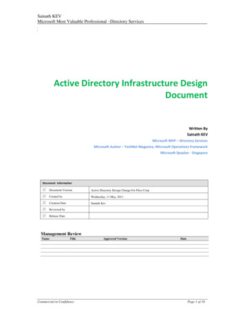
Series 401,402, & 403 Installation InstructionsSECTION III: A. SCREW SPLINE FABRICATIONREVIEW THE GENERAL NOTES ONPAGE 3 BEFORE PROCEEDING.STEP 1) Apply butyl sealant (S.M. 5504, typ.) to ends of all horizontalsbefore assembling units.STEP 2) Assemble the unit as shown in Fig. # 6 below.These basic assembly procedures apply to all storefront products.# S129Apply butyl type sealant
Glass Stop. Use W/9121, 9146 or 9149 9131 OBSOLETE 9137 OBSOLETE 9160 2 9/16" Deep Adjustable Side Lite Base Horiz. W/ BRK. MTL. Use W/9161 Vertical Use (2) 9133 Glass Stops Use W104 Weathering 9161 2 9/16" Deep Adjustable Side Lite Base Vertical W/BRK. MTL. Use W/ 9160 Horizontal 1G13 4 ½" Deep Adjustable Side Lite Base Horizontal W/BRK .