Transcription
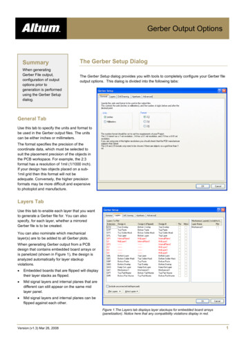
Gerber Output OptionsSummaryWhen generatingGerber File output,configuration of outputoptions prior togeneration is performedusing the Gerber Setupdialog.The Gerber Setup DialogThe Gerber Setup dialog provides you with tools to completely configure your Gerber fileoutput options. This dialog is divided into the following tabs:General TabUse this tab to specify the units and format tobe used in the Gerber output files. The unitscan be either inches or millimeters.The format specifies the precision of thecoordinate data, which must be selected tosuit the placement precision of the objects inthe PCB workspace. For example, the 2:3format has a resolution of 1mil (1/1000 inch).If your design has objects placed on a sub1mil grid then this format will not beadequate. Conversely, the higher precisionformats may be more difficult and expensiveto photoplot and manufacture.Layers TabUse this tab to enable each layer that you wantto generate a Gerber file for. You can alsospecify, for each layer, whether a mirroredGerber file is to be created.You can also nominate which mechanicallayer(s) are to be added to all Gerber plots.When generating Gerber output from a PCBdesign that contains embedded board arrays oris panelized (shown in Figure 1), the design isanalyzed automatically for layer stackupviolations. Embedded boards that are flipped will displaytheir layer stacks as flipped. Mid signal layers and internal planes that aredifferent can still appear on the same midlayer panel. Mid signal layers and internal planes can beflipped against each other.Figure 1.The Layers tab displays layer stackups for embedded board arrays(panelization). Notice here that any compatibility violations display in red.Version (v1.3) Mar 26, 20081
OG0101 Gerber Output OptionsDrill Drawing TabUse this tab to specify which layer-pairs a drilldrawing is required for (mirrored output files canalso be generated). You can also specify thetype and size of drawing symbol to be used torepresent the various drill sizes.Use this tab also, to specify which layer-pairs adrill guide file is required for (mirrored output filescan also be generated). The drill guide is a plotof the location of each drill site on the PCB, witheach site marked with a small cross.Apertures TabUse this tab to enable/setup the requiredaperture information for the design.When you enable the Embedded apertures(RS274X) option, the aperture list is createdautomatically, each time you generate theGerber files. The apertures are then embedded in the Gerber files, according to the RS274X standard. This feature means thatyou do not need to worry about whether thecurrent aperture list includes all the requiredapertures.If you do not enable this option, the mainapertures region of the tab becomes enabled,from where you can load, create, edit and savean aperture table exactly as you require.When creating new apertures, the DCode dialogappears. You can define up to a maximum of1000 different draft codes, in the range D00-D9999, although some of these codes (usuallyD00-D09) may be "reserved" when targeting some plotters, so use of these codes is notgenerally recommended. Do not include the "D" in any new draft code you enter.After entering a new code, you will be transferred to edit mode and the Aperture dialog willappear, from where you can edit the properties of the aperture as required.Any changes made are applied to the aperture file currently loaded into memory. Thesechanges do not become permanent until you use the Save button (on the Apertures tab ofthe Gerber Setup dialog).Version (v1.3) Mar 26, 20082
OG0101 Gerber Output OptionsAdvanced TabUse this tab to specify options such as thevirtual film size to be used during Gerbergeneration, aperture matching tolerances andthe use of zero suppression.The Gerber data can be automaticallycentered on the specified film by enabling theCenter on film option.Use this tab to also specify the type of outputplotter to be used - either vector or raster.Version (v1.3) Mar 26, 20083
OG0101 Gerber Output OptionsGenerated Gerber FilesThe following table lists each of the Gerber files that can possibly be generated as output from a PCB document. In each case,the Gerber file is generated with the same name as the PCB document (i.e. PCBDesignName.GerberExtension).Gerber ExtensionDescriptionG1, G2, etcMid-layer 1, 2, etcGBLBottom LayerGBOBottom OverlayGBPBottom Paste MaskGBSBottom Solder MaskGD1, GD2, etcDrill Drawing (assignment based on order of drill pairs appearing in the Drill-Pair Manager dialog)GG1, GG2, etcDrill Guide (assignment based on order of drill pairs appearing in the Drill-Pair Manager dialog)GKOKeep Out LayerGM1, GM2, etcMechanical Layer 1, 2, etcGP1, GP2, etcInternal Plane Layer 1, 2, etcGPBPad Master BottomGPTPad Master TopGTLTop LayerGTOTop OverlayGTPTop Paste MaskGTSTop Solder MaskP01, P02, etcGerber PanelsAPRAperture File (generated when embedded apertures (RS274X) are used)APTAperture File (generated when embedded apertures (RS274X) are not used)In addition, the following files are also generated: PCBDesignName.rul – this file contains all design rules defined for the source PCB document from which the Gerber datais being generated. This file is generated provided that the Generate DRC Rules export file (.RUL) option is enabled on theAdvanced tab of the Gerber Setup dialog. PCBDesignName.rep – this file provides a generation report, showing which Gerber files have been generated.When embedded apertures (RS274X) are not used, a separate text-based aperture file will be generated for each generatedGerber layer - for example, GBL will have an associated aperture file with extension ABL. Each of these files is identical in itscontent. The true Gerber aperture file is distinguished by its .apt extension in this case.NotesUse the dialog's 'What's This Help' feature to obtain detailed information about each of the options available. Click the '?' buttonat the top right of the dialog and then click over a field or option to pop-up information specific to that field or option.Gerber output can be generated in one of two ways:Version (v1.3) Mar 26, 20084
OG0101 Gerber Output Options Using an appropriately configured output generator defined in an Output Job Configuration file (*.OutJob). Output will begenerated upon running the configured output generator Directly from within the active PCB document using the File » Fabrication Outputs » Gerber Files menu command. Outputwill be generated immediately upon clicking OK in the Gerber Setup dialog.Note: The settings defined in the Gerber Setup dialog when generating output directly from the PCB are distinct and separate tothose defined for the same output type in an Output Job Configuration file. In the case of the former, the settings are stored inthe project file, whereas for the latter they are stored in the Output Job Configuration file.When generating Gerber output, you can specify that the output be opened automatically in a new CAM document. The way inwhich this is accomplished depends on how you are generating the output: From an Output Job Configuration file - enable the Gerber Output auto-load option in the Output Job Options dialog (Tools» Output Job Options from the OutputJob Editor) Directly from the PCB - ensure that the Open outputs after compile option is enabled on the Options tab of the OptionsFor Project dialog (Project » Project Options).Unless your PCB manufacturer does not support embedded apertures it is highly recommended that you use the Embeddedapertures (RS274X) option. Most modern photoplotters are raster plotters which can accept any size aperture. Generally, theyalso accept Gerber files with embedded apertures.If your manufacturer doesn't use embedded apertures, a separate aperture file (*.apt) should be included with the Gerber files.A special aperture must be provided for any file when holes are defined for any pads or vias in the PCB file. This is because thePCB Editor needs to provide an aperture for stroking Drill Drawing symbols and/or text. The aperture is required even if you arenot generating a Drill Drawing plot. If no holes are in the file (eg. no vias, all pad holes defined as 0), the aperture is notrequired.When you use an existing aperture file, the PCB Editor scans the primitives (tracks, pads, etc) in the PCB document andmatches these with aperture descriptions in the loaded *.apt file. If there is no exact match of aperture to primitive, the PCBEditor will automatically "paint" the primitive with a suitable smaller aperture. If there is no aperture suitable to "paint" with, a*.MAT (match) file will be generated listing the missing apertures and Gerber file generation will be aborted.If using automatic aperture generation the required apertures for Drill Drawing symbols and other text is automatically providedwith the stroke width being proportional to the text height. For example, the default 50 mil Drill Drawing symbol size yields a 7milaperture for stroking the symbols. 60 mil text height yields 8 mils stroke width. You should take care in defining text sizes forSilkscreen (or Overlay) layers, as very fine strokes may not be successfully screened onto the board.The Gerber file extension naming convention conforms to general industry practice.Check with your manufacturer to see if they can accept PCB files directly. Many manufacturers will be able to produce a PCBdirectly from a binary PCB file.Contact your photoplot bureau before generating any photoplots. Matching available plotting options at the edit level can saveconsiderable time and expense when generating Gerber phototools.The output path for generated files is set in the Options tab of the Options for Project dialog. By default, the output path is set toa sub-folder under the folder that contains the Project file and has the name: Project Outputs for ProjectName. The outputpath can be changed as required. If the option to use a separate folder for each output type has been enabled in the Optionstab, then the Gerber files will be written to a further sub-folder, named: Gerber Output.Version (v1.3) Mar 26, 20085
OG0101 Gerber Output OptionsWhen generated, the output will be added to the project and appear in the Projects panel under the Generated folder, in anappropriately-named sub-folder. If you have used a separate folder for each output type, then corresponding (separate)Generated folders will be added to the Projects panel (e.g. Generated (Gerber Output)).Revision HistoryDateVersion No.Revision05-Dec-20051.0New release12-Apr-20071.1Updated for Altium Designer 6.74-Mar-20081.2Updated Page Size to A4.26-Mar-20081.3Minor update.27-Jul-2011-Updated template.Software, hardware, documentation and related materials:Copyright 2011 Altium Limited.All rights reserved. You are permitted to print this document provided that (1) the use of such is for personal use only and will not be copied orposted on any network computer or broadcast in any media, and (2) no modifications of the document is made. Unauthorized duplication, inwhole or part, of this document by any means, mechanical or electronic, including translation into another language, except for brief excerpts inpublished reviews, is prohibited without the express written permission of Altium Limited. Unauthorized duplication of this work may also beprohibited by local statute. Violators may be subject to both criminal and civil penalties, including fines and/or imprisonment.Altium, Altium Designer, Board Insight, DXP, Innovation Station, LiveDesign, NanoBoard, NanoTalk, OpenBus, P-CAD, SimCode, Situs,TASKING, and Topological Autorouting and their respective logos are trademarks or registered trademarks of Altium Limited or its subsidiaries.All other registered or unregistered trademarks referenced herein are the property of their respective owners and no trademark rights to thesame are claimed.Version (v1.3) Mar 26, 20086
Generated Gerber Files The following table lists each of the Gerber files that can possibly be generated as output from a PCB document. In each case, the Gerber file is generated with the same name as the PCB document (i.e. PCBDesignName.GerberExtension). Gerber Extension Description G1, G2, etc Mid-layer 1, 2, etc GBL Bottom Layer