Transcription
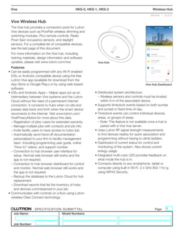
VivePowPak Single Zone Control Module with EcoSystemWireless Lighting Control3691103e 1 06.02.20PowPak Single Zone Control Modulewith EcoSystemThe PowPak Single Zone Control Module withEcoSystem is a radio frequency (RF) control thatoperates up to 32 EcoSystem LED drivers or fluorescentballasts for the purpose of high performance dimmingand control in a Vive system or with Vive standaloneproducts. This control is based on input from Picoremote controls and Radio Powr Savr sensors. Thecontrol module is ideal for small areas (e.g., classrooms,conference rooms, private offices).Communication with RF input devices (e.g., Pico remotecontrols, Radio Powr Savr sensors) is accomplished byusing Lutron Clear Connect RF technology.These products are also compatible with the Vive hubwhich enables a simple setup process using the freeLutron Vive app (available for download from the AppStore or Google PlayR online marketplace) or by usingweb-based software with any Wi-FiR enabled iOSR orAndroidR compatible device. It also enables control andmonitoring of all Vive devices. The Vive hub can beadded at any time. System reprogramming will berequired. For a complete list of features supported withthe Vive hub, see specification submittal 369902. FeaturesCompatible with any Lutron EcoSystem LED driver or Utilizes Lutron Clear Connect RF Technology; refer toballast for high performance dimming and control.model number chart below for frequency band data.Controls up to 32 EcoSystem fixtures in a single zone. Mounts to a 4 in x 4 in (102 mm x 102 mm) squarejunction box through a 0.5 in (20 mm) knockout.– All fixtures will be at the same light level and cannot beindividually controlledConfigurable high- and low-end trim.Receives wireless inputs from up to 10 Pico remotecontrols, 10 Radio Powr Savr occupancy / vacancysensors, and 1 Radio Powr Savr daylight sensor.ModelsModel NumberDescriptionRegionOperating VoltageRMJS-ECO32-SZ 32 device controller U.S.A., Canada, Mexico 120 –277 V Israel, Hong Kong220 –240 V Frequency Band431.0 –437.0 MHz433.05 –434.79 MHzNote: Contact Lutron for frequency band compatibility for your geographic region if it is not indicated above. Job Name:Job Number:S P E C I F I C AT I O N S U B M I T TA LModel Numbers:Page1
VivePowPak Single Zone Control Module with EcoSystemWireless Lighting Control3691103e 2 06.02.20SpecificationsRegulatory Approvals UL Listed FCC approved. Complies with the limits for a Class Bdevice, pursuant to Part 15 of the FCC rules DALI-2 Certified (IEC 62386) cUL and IC NOM UL 2043 Plenum Rated Classified in accordance with CAN / ULC-S142as discrete product certified for installation in anair-handling space. Compatible with DALI-compliant loadsPower 120 –277 V 50 / 60 Hz, max. current 80 mAOther Power Specifications Standby power:120–277 V 1.0 WSystem Communication Operates using Clear Connect RF Technology forreliable wireless communication Wireless sensors and controls must be located within30 ft (9 m) of the associated control module.Key Design Features LED status indicator shows load status and providesprogramming feedback Configurable high-end and low-end trim Power failure memory: If power is interrupted,connected loads will return to the previous level priorto interruptionEnvironment Ambient operating temperature: 32 F to 104 F(0 C to 40 C) 0% to 90% humidity, non-condensing For indoor use onlyMounting This device can be installed on a junction boxor marshalling box using the conduit nut or withmounting screws and must be installed away froma fixture / troffer. The device must NOT be mountedinside or on a fixture / troffer or other metallicenclosure. For applications where code requires the PowPakControl Module to be installed inside an additionaljunction box (e.g., U.S.A.), please see LutronApplication Note #423 (P/N 048423) atwww.lutron.com. For all other installations, refer tothe installation instructions and consult local andnational electric codes for proper installation. The PowPak Control Module needs to be accessiblefor some programming steps. Record where it ismounted so that it can be easily located later.NOTICE: Improper installation can result indegraded wireless communication and/orintermittent or sustained communication failures,and will not be covered under warranty.Metal Ceiling Mounting Metal ceiling grids must have a 0.12 in (3 mm) gapof non-metal material which extends the entire lengthof the tile on at least one edge. This is often achievedby foam spacers that are used to prevent tile-to-tilerattling. Metal ceiling grids which are continuous (with nogap) or those that are interlocked, must have a totalsurface area that is less than 900 ft2 (81 m2) foreach section. The overall space can be larger aslong as there are non-metal sections bordering orintersecting the metal sections.Continued on next page. Job Name:Job Number:S P E C I F I C AT I O N S U B M I T TA LModel Numbers:Page2
VivePowPak Single Zone Control Module with EcoSystemWireless Lighting Control3691103e 3 06.02.20Specifications (continued) EcoSystem / DALI Link18 VGuaranteed Supply Current: 64 mAMaximum Supply Current: 250 mAConnects to Lutron EcoSystem LED drivers or ballasts– Controls up to 32 EcoSystem drivers or ballasts– Multiple drivers / ballasts connected to a ControlModule will always work together as a single zoneCan be wired as Class 1 or IEC PELV / NECR Class 2.For more details, see Lutron Application Note #142(P/N 048162) at www.lutron.comPolarity freeTopology freeThe PowPak Control Module is a single master controllerand therefore no other controllers may exist on thesame link.Ensure that there is no greater than a 2 V dropbetween the Control Module and the end of the link.Note: Wired sensors connected to EcoSystem devicesare NOT supported.Wire Gauge Default OperationAssociated wireless input devices control allconnected fixtures togetherOccupancy Sensors:– Occupied: 100%; Unoccupied: 0% (OFF)Pico Remote Controls:– On: 100%; Favorite Level: 50%; Off: 0% (OFF)Daylight Sensor: Decreases electric light in responseto additional available daylightTotal Digital Link Wire Lengthmm2)12 AWG (4.014 AWG (2.5 mm2)16 AWG (1.5 mm2)18 AWG (1.0 mm2)EcoSystem2200 ft (671 m)1400 ft (427 m)900 ft (275 m)570 ft (175 m)DALI984 ft (300 m)*984 ft (300 m)*900 ft (275 m)570 ft (175 m)Lutron Qualified DALI Control Gear Lutron requires that all DALI devices that are intended tobe used with a Lutron controller must be pre-tested byLutron and determined to be compatible before beingused on a project. For a complete list of Lutron qualified DALI ballastsplease refer to Application Note #482 (P/N 048482) atwww.lutron.com* Maximum recommended length as per IEC 62386-101 Ed. 2.0 Job Name:Job Number:S P E C I F I C AT I O N S U B M I T TA LModel Numbers:Page3
VivePowPak Single Zone Control Module with EcoSystemWireless Lighting Control3691103e 4 06.02.20Advanced ConfigurationsPico Remote Controls Up to 10 Pico remote controls Favorite levels can be set for each Pico remote controlRadio Powr Savr Daylight Sensor The Radio Powr Savr daylight sensor will affect allconnected LED drivers and ballasts equally For multiple rows of daylighting, a separate PowPakControl Module must be used for each daylighting rowMinimum Light Level Setting (optional) Certain applications, such as hallways, may requirethat the lights never turn off. For these areas, selectthe minimum light level option and the load will lowerto programed low-end level. Default operation lowersto OFF.High- and Low-End Trim High-end and low-end trim affect all connected fixturesequally, and can be configured from the PowPakControl Module. Adjustable low-end trim (0.1% –45%)*. Trimmablelow‑end can ensure a stable light level. Some fixtureswill flicker or drop out if trimmed too low. The maximum light output of connected fixtures can bedecreased down to 55% for energy savings in over-litspaces.Note: The perceived light output of low-end trim mayvary between fixture manufacturers and modelnumbers. For best results, do not mix different driversor ballasts on the same EcoSystem circuit.Radio Powr Savr Occupancy Sensors Radio Powr Savr occupancy and vacancy sensorscontrol all connected drivers or ballasts. Pico remote controls can be used to adjust theoccupied levels of fixtures that they control from0.1%* to 100% (of output signal) or can make themunaffected by occupancy events. Vacancy events (area becomes unoccupied) turn alldriver or ballast models off or to minimum light level.* Low-end depends on the minimum output of the connecteddrivers or ballasts. Job Name:Job Number:S P E C I F I C AT I O N S U B M I T TA LModel Numbers:Page4
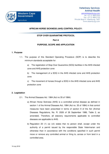
VivePowPak Single Zone Control Module with EcoSystemWireless Lighting Control3691103e 5 06.02.20System DiagramEcoSystem controlPico Remote Control (up to 10)LED DriversTo additional fixtures(32 devices maximum)Fluorescent BallastsRadio Powr Savr Occupancy Sensor (up to 10)Radio Powr Savr Daylight Sensor (up to 1)Note: Multiple drivers / ballasts connected to a PowPak Control Modulewill always work together as a single zone.Note: The perceived light output of low-end trim may vary betweenfixture manufacturers and model numbers. For best results, do not mixdifferent drivers or ballasts on the same EcoSystem circuit.Wiring SchematicJunction BoxLine / HotNeutralE1/DA EcoSystem to LED Drivers / FluorescentBallastsE2/DA-0.5 in (21 mm) trade-size knockout opening Job Name:Job Number:S P E C I F I C AT I O N S U B M I T TA LModel Numbers:Page5
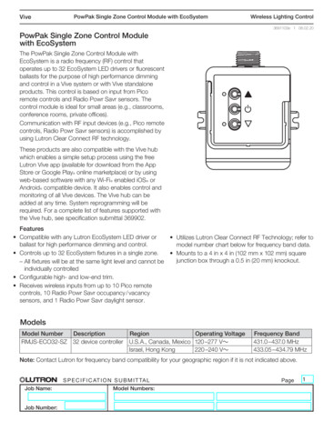
VivePowPak Single Zone Control Module with EcoSystemWireless Lighting Control3691103e 6 06.02.20DimensionsDimensions are shown as: in (mm)0.5 in (21 mm) trade-sizeknockout opening3.42(87)3.94(100)2.82(72)1.25(32)Wireless Range DiagramPowPakControl ModuleInstall in center of roomto maximize RF coverage.Radio Powr SavrOccupancySensorPowPakControlModule30 ft (9 m)maximumPicoRemoteControl ote: Wireless sensors and controls must be located withinN30 ft (9 m) of the associated control module. Metal ceiling grids must have a 0.12 in (3 mm) gap of nonmetal material which extends the entire length of the tile on atleast one edge. This is often achieved by foam spacers thatare used to prevent tile-to-tile rattling. Metal ceiling grids which are continuous (with no gap) orthose that are interlocked, must have a total surface areathat is less than 900 ft2 (81 m2) for each section. The overallspace can be larger as long as there are non-metal sectionsbordering or intersecting the metal sections.Lutron, the Lutron logo, PowPak, Clear Connect, Vive, Radio Powr Savr, andPico are trademarks or registered trademarks of Lutron Electronics Co., Inc. inthe US and/or other countries.App Store is a service mark of Apple Inc.All other product names, logos, and brands are property of theirrespective owners. Job Name:Job Number:S P E C I F I C AT I O N S U B M I T TA LModel Numbers:Page6
Lutron Vive app (available for download from the App Store or Google PlayR online marketplace) or by using . Vive PowPak Single Zone Control Module with EcoSystem Wireless Lighting Control 3691103e 2 06.02.20 . Power failure memory: If power is interrupted, connected loads will return to the previous level prior to interruption