Transcription
ViveHKS-0, HKS-1, HKS-2Wireless Hub3691044o 1 03.23.21Vive Wireless HubThe Vive hub provides a connection point for LutronVive devices such as PowPak wireless dimming andswitching modules, Pico remote controls, RadioPowr Savr occupancy sensors, and daylightsensors. For a complete list of compatible devices,see the last page of this document.For more information on the Vive hub, includingtraining materials, design information and softwareupdates, please visit www.lutron.com/viveFeatures Can be easily programmed with any Wi-Fi enablediOS or Android compatible device using the freeLutron Vive app (available for download from theApp Store or Google Play ) or by using web-basedsoftware. iOS and Android Apps – Helper apps act as anintermediary between Vive systems and the LutronCloud without the need of a permanent internetconnection. It connects to hubs when on-site andpasses data back and forth when the smart devicereconnects to the Internet. Visit www.lutron.com/VivePrivacyNotice for more about this data.– Registration of jobs / users for extended warranty.– Manage multiple jobs with contacts and job info.– Invite facility users to have access to hubs / job.– Automatically send hand-off documentationpersonalized to your firm to facility managementteam. Including programming user guide, online"How-to" videos, and support number.– Connection to hub browser user interface forsetup. Normal web browser still works and theapp is not required.– Connection to hub browser dashboard for controland monitor. Normal web browser still works andthe app is not required.– Backup the database to the Lutron Cloud for hubreplacement.– Download reports that list the inventory of hubsand devices commissioned in your job. Communicates with controls on a floor using Lutronwireless Clear Connect technology. Job Name:Job Number:S P E C I F I C AT I O N S U B M I T TA LModel Numbers:Vive HubVive Hub Dashboard Distributed system architecture.– Wireless sensors and controls must be locatedwithin 9 m of the associated device. Supports timeclock events based on both sunriseand sunset or fixed time-of-day. Timeclock events can control individual devices,areas, or groups of areas.– Note: This feature is not available once a hub ispaired with a Vive Vue server. Uses Lutron RF signal strength measurementsto find devices nearby for quick association andprogramming without having to climb ladders. Dashboard of current status for control andmonitoring of the system. Also shows currentenergy usage. Integrated multi-color LED provides feedback onwhat mode the hub is in. Connects directly to any smartphone, tablet orcomputer using built in Wi-Fi. 2.4 GHz 802.11b / gusing WPA2 Security.Page1
ViveHKS-0, HKS-1, HKS-2Wireless Hub3691044o 2 03.23.21 Features (continued)Ethernet 10 / 100 Mbps connection for:– Native BACnet / IP (see Lutron P/N 369996 atwww.lutron.com for PIC Statement) integrationinto Building Management Systems (HKS-2-XXonly). The Vive Hub has been tested by BACnet Testing Laboratories (BTL) and is certifiedto comply with all necessary interoperabilityrequirements.– Network multiple Vive hubs together as anindependent system or as part of an existingbuilding network.– Native OpenADR support, to manage AutomaticDemand Response / Load Shed events dictated bya utility company.– Each Vive hub hosts a unique virtual BACnet network. As such, each Vive hub requires a uniqueBACnet network number.Firmware upgradable for future features and securitypatches.Password protected access.Flush-mount or surface-mount options available.Supported on most devices that use an HTML5compliant browser (iOS , Android , Windows ,Mac ).Required browsers are Google Chrome and Safari .Supports HTTPS.Recommended configurations for smart devices:DeviceOS VersioniPhone 6, iPhone 6 plus or neweriOS 11 or laterSupported on most Android devicesrunning Android 6.0 or later.Android 6.0 or later Daylighting Setpoint Tweaking – If the lights are toobright or too dim while using daylighting, adjust thesettings in real time from a smart device to alterthe setpoint for the light level that is maintainedbetween natural and electric light. Older devices(released prior to September 2017) can be adjustedbut may take a minute to reach the desired levelbecause of a of slow fade. New devices will respondimmediately. Job Name:Job Number:S P E C I F I C AT I O N S U B M I T TA LModel Numbers: Daylighting-to-Low-End or Daylighting-to-Off - TheVive system will allow the user to select eitherdaylighting-to-low-end or daylight-to-off on an areaby area basis.– Requires Vive hub software 01.08 or higher. Customer Supplied Security Certificates– Provides customers the abiltiy to load their ownauthentication certificates for their specific domain.– Provides customers using the Vive hub applicationto use secure browser communications withoutreceiving any authentication warnings due to theself-signed certificates that are shipped with thehubs.– Requires Vive hub software 01.08 or higher. Timeclock Occupancy Sensor Settings Changes– Requires devices shipped after September2017. Devices shipped prior to that date will bedisplayed as "unsupported" in the software UI.Allows timeclock events to change the behaviorof occupancy settings based on time of day.For example, change the unoccupied level ofcorridors / hallways from 25% during the day, andoff at night. The following settings can be changed:– Occupied Level – The level the lights go to whenoccupied. Changes are not applied immediatelyto currently occupied spaces, but will change thenext time the space goes occupied to minimizedistraction.– Unoccupied Level – The level the lights go to whenunoccupied. Changes are applied immediately tospaces not currently occupied.– Enable / Disable Occupancy – Change whetherdevices will respond to the occupancy sensor.– Timeout of the sensors (requires FC-VSENSOR).LRF2 sensors still require this setting to be set onthe sensor. 365-day schedulable timeclock with exceptionsfor holidays.– Allows scheduling events 10 years in advance.– Set recurring events with exceptions on holidays.– Allows scheduling events on specific day of theyear.Page2
ViveHKS-0, HKS-1, HKS-2Wireless Hub3691044o 3 03.23.21Features (continued) Provides calculated energy data forPowPak modules. Create and edit areas. Tune area light levels by trimming the high-end andlow-end output. Adjust occupancy settings. Create occupancygroups. User can choose to extend the RF range of up to15 of the total Pico remote controls per Vive hub.These remotes will be able to control any deviceswithin the 22 m range. RF range of occupancy sensors can be extendedfor up to 14 areas per Vive hub. In a range-extendedarea, an occupancy sensor can control any devicein that area, regardless of distance between sensorand device. Requires Vive hub software 01.09or higher. Configurable Fade Time– Up to 90 minutes for timeclock events and scenes.o Limited to 90 seconds for RMKS-DAL32-SZ andRMKS-DAL4-SZ devices.o NOTE: This feature is not available once a hub ispaired with a Vive Vue server.– Up to 90 seconds for Pico remote controlprogramming.o Fade time may differ between buttons on thesame Pico remote control.o Single fade time applies to all programming fora button. Automatic Demand Response / Load Shed– Load Shedding will physically dim the lights to aprogrammable level.– OpenADRR 2.0b compliant (requires Vive hubsoftware 01.09 or higher).– May be enabled (or disabled) via any of thefollowing methods:o The first contact closure input (CCI 1)o BACnetR integrationo OpenADRR integration– OpenADRR requires access to utility companiesover the Internet, so the hub must be connectedvia Ethernet to use OpenADRR. Job Name:Job Number:S P E C I F I C AT I O N S U B M I T TA LModel Numbers: Alerts– View run-time issues which may prevent devicesfrom operating as expected, such as low batteries ormissing devices. API Integration– To integrate with third-party devices, systems,and software, RESTful APIs are available overthe Ethernet. Scenes– Scenes can control individual devices, areas, orgroups of areas on demand.– May be activated via any of the following methods:o The second contact closure input (CCI 2)o API integrationo Manual activation in the app– Maximum of 50 scenes are supported.– Requires Vive hub software 01.13 or higher. Programmable CCI– The second contact closure input (CCI 2) can beprogrammed to activate a scene.– Scene activationo Set a scene to activate using second contactclosure input (CCI 2) on the Vive hub.– Requires Vive hub software 01.13 or higher Occupancy Dependency– Occupancy sensors in one room/area can controldevices in other rooms/areas.– Radio Powr Savr occupancy sensors and MaestroWireless 0–10 V- dimmers and switches withsensor only.– Requires Vive hub software 01.14 or higher.Page3
ViveHKS-0, HKS-1, HKS-2Wireless Hub3691044o 4 03.23.21SpecificationsRegulatory Approvals CE (European Union)Power / Performance Input to power supply:220 – 240 V 50 / 60 Hz 0.6 A Input to Vive hub:24 V- 350 mASystem Limits HKS-1, HKS-2 support up to 700 Lutron Wirelessdevices. HKS-0 supports 75 Lutron Wireless devices. Any given load device can be controlled by 10 occupancysensors, 10 Pico remote controls and 1 daylight sensor(Pico remote controls and sensors must be located within9 m of the load device they are controlling).Metal Ceiling Mounting Metal ceiling grids must have a 3 mm gap of non-metalmaterial which extends the entire length of the tile on atleast one edge. This is often achieved by foam spacersthat are used to prevent tile-to-tile rattling. Metal ceiling grids which are continuous (with no gap) orthose that are interlocked, must have a total surface areathat is less than 81 m2 for each section. The overall spacecan be larger as long as there are non-metal sectionsbordering or intersecting the metal sections. Do not install the Vive hub above metal ceilings or tileswith a metal backing.Mounting Use surface-mount version for mounting to a hard orcement ceiling. Power supply mounts to a Lutron-supplied US-style101.6 mm x 101.6 mm (4 in x 4 in) junction box. Power supply must be mounted within 30 m of the Vivehub. Wiring should be 0.2 mm2 to 2.5 mm2(24 AWG to 12 AWG).Environment Job Number: First contact closure input (CCI 1) is to be used forinitiating load shed only. The second contact closure input (CCI 2) may beprogrammed to activate a scene.If activating a scene, a "deactivation" behavior may beset in the scene in order to set two behaviors for theone input. Accepts only maintained inputs. Off-state leakage current must be less than 100 μA. Open circuit voltage: 24 V- maximum. Input wiring: 0.2 mm2 to 2.5 mm2 (24 AWG to 12 AWG). Contact Closure Inputs on multiple hubs can be wiredin parallel. DO NOT wire inputs in parallel with otherequipment as it can cause the inputs on either of thedevices to falsely trigger. Up to 4 hubs in parallel. To ensure proper operation of Contact Closure Inputs,a PS-K-20W-240 power supply may not be used toprovide power to more than one hub. Inputs must be dry contact closure, solid state, opencollector, or active-low (NPN) / active high (PNP) output.– Open collector NPN or active-low on-state voltagemust be less than 2 V and sink 3.0 mA.– Open collector PNP or active-high on-state voltagemust be greater than 12 V and source 3.0 mA.Programming The Vive Hub is meant to be permanently installed. Itis not intended to be used as a programming tool thatcan be removed from the site after commissioning.Various Vive system features are dependent on thehub for proper functionality. In addition, users andother maintainers will be forced to recommission theentire system in order to make simple changes oradditions if the hub is not installed on-site as part of thecommissioned system.Warranty For indoor use only. 0 C to 40 C. Relative humidity less than 90% non-condensing.Job Name:Contact Closure Input TerminalsS P E C I F I C AT I O N S U B M I T TA LModel Numbers: 2 year limited warranty. The customer can register theproduct to increase the warranty period from2 year to 5 years. Please /Limited%20Comm.pdf for warranty details.Page4
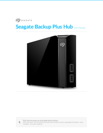
ViveHKS-0, HKS-1, HKS-2Wireless Hub3691044o 5 03.23.21How to Build a Model NumberExampleHKS – 1 – FMFrequencyTypeMountingFrequencyReplacement Part Model NumbersK 868.125 – 868.250 MHz (United Kingdom)PS-K-20W-240H-MOUNT-FMH-MOUNT-SMTypeVive hub external power supplyFlush-mount installation adapterSurface-mount installation adapter0 Starter Vive hub without BACnetR limited to75 devices. (Available as HKS-0-FM only)1 Vive hub without BACnetR2 Premium Vive hub with BACnetRMountingFM Flush-Mount (non-metal ceiling tiles or drywall)SM Surface-Mount (cement)Available Vive Hub Model Numbers (includes powersupply and mounting adapter)HKS-0-FM - Starter Vive hub, flush-mount adapter andpower supplyHKS-1-FM - Vive hub, flush-mount adapter andpower supplyHKS-1-SM - Vive hub, surface-mount adapter andpower supplyHKS-2-FM - Premium Vive hub, flush-mount adapterand power supplyHKS-2-SM - P remium Vive hub, surface-mount adapterand power supplyHKS-UPDATE - S oftware upgrade license to addBACnet to HKS-0 and HKS-1 hubsHKS-DEVICES - S oftware upgrade license expandsdevice limit to 700 devices forHKS-0 hubs Job Name:Job Number:S P E C I F I C AT I O N S U B M I T TA LModel Numbers:Page5
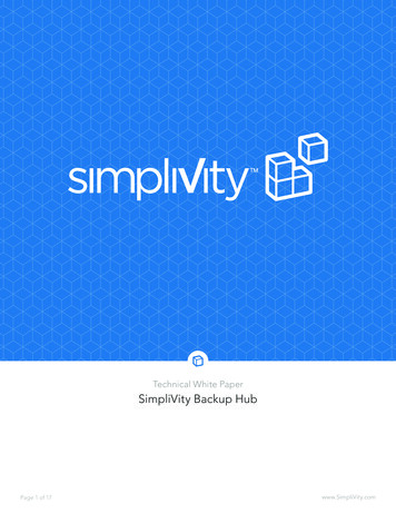
ViveHKS-0, HKS-1, HKS-2Wireless Hub3691044o 6 03.23.21DimensionsDimensions are shown as: mmVive HubSide ViewTop View1357117338Flush-mount AdapterSide ViewTop ViewFlush-mountAdapter Details79 Requires a 153 mmhole to be cut in theceiling for mounting.165Surface-mount AdapterSide ViewTop View89Surface-mountAdapter Details122122 Knockouts forconduit.Power SupplySide ViewTop View861024386102 Job Name:Job Number:S P E C I F I C AT I O N S U B M I T TA LModel Numbers:Page6
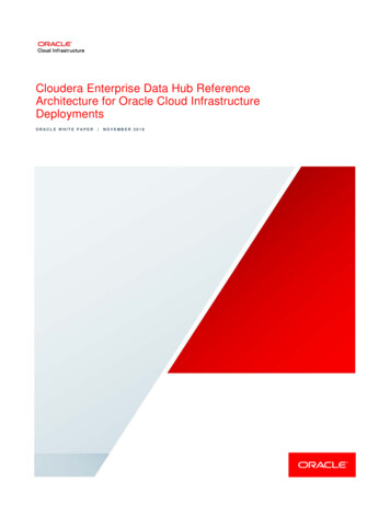
ViveHKS-0, HKS-1, HKS-2Wireless Hub3691044o 7 03.23.21Range DiagramsAll wireless devices to be associated to the Vive hub must be within 22 m of the Vive hub and must be on the samefloor as the Vive hub.Note: Vive hubs should be mounted greater than 3 m apart on the same floor.Note: Lutron requires that the Vive hub not be installed above metal ceilings or tiles with a metal backing.Note: A corporate Wi-Fi network can interfere with the Wi-Fi on the Vive hub. Where a corporate Wi-Fi network exists,it is recommended to do the following: Connect the Vive hub to the corporate network using the Ethernet connection on the hub and disable Wi-Fi onthe hub.Note: Vive hubs should be mounted greater than 3 m from a Wi-Fi router or access point.Conference RoomPowPak Dimming ModuleVive Hub RFcoveragePrivate OfficePowPak DimmingModule9mMaximum 1Personal ControlPico Remote Control30 m9mMaximum 122 mMaximumSensorsRadio Powr SavrOccupancy SensorOpen OfficePowPak Relay Module9mMaximum 1Setup, Monitorand Control9mMaximum 130 mVive Hub1Range with multiple Vive hubs30 m22 mMaximum22 mMaximum NOTE: Wireless sensors and controls must be located within9 m of the associated control module. Metal ceiling grids must have a 3 mm gap of non-metalmaterial which extends the entire length of the tile on at leastone edge. This is often achieved by foam spacers that areused to prevent tile-to-tile rattling. Metal ceiling grids which are continuous (with no gap) or thosethat are interlocked, must have a total surface area that isless than 81 m2 for each section. The overall space can belarger as long as there are non-metal sections bordering orintersecting the metal sections.30 m Job Name:Job Number:S P E C I F I C AT I O N S U B M I T TA LModel Numbers:Page7
ViveHKS-0, HKS-1, HKS-2Wireless Hub3691044o 8 03.23.21Wiring and MountingProduct OverviewSupplied US-style junction box(Flush-mount adapter)24 V220 –240 V Flush-mountadapterCeiling tilePower supplyVive hubProduct OverviewSupplied US-style junction box(Surface-mount adapter )24 VSurface-mountadapterCeiling220 –240 V Power supplyVive hubVive HubEthernetConnectionEthernet10/100LANOptional: Only used for automatic demand response / load shed viafirst contact closure input (CCI 1)CCI1COMCCI224 VCOMOptional: Scene via second contact closure input (CCI 2)RedBlue Job Name:Job Number:S P E C I F I C AT I O N S U B M I T TA LModel Numbers:To PowerSupplyPage8
ViveHKS-0, HKS-1, HKS-2Wireless Hub3691044o 9 03.23.21Vive Security StatementLutron takes the security of the Vive Lighting Control System very seriously.The Vive Lighting Control System has been designed and engineered with attention to security since its inception.Lutron has engaged security experts and independent testing firms throughout the entire development of the ViveLighting Control System. Lutron is committed to security and continuous improvement throughout the Viveproduct lifecycle.The Vive Lighting Control System uses a multi-tiered approach to security.They include:1. An architecture that isolates the wired Ethernet network from the wireless network, which strictly limits thepossibility of the Vive Wi-Fi being used to access the corporate network and gain confidential information2. A distributed security architecture with each hub having its own unique keys that would limit any potential breachto only a small area of the system3. Multiple levels of password protection (Wi-Fi network and the hubs themselves), with built-in rules that force theuser to enter a strong password4. ISO-recommended best practices including salting and SCrypt for securely storing usernames and passwords5. AES 128-bit encryption for network communications6. HTTPS (TLS 1.2) protocol for securing connections to the hub over the wired network7. WPA2 technology for securing connections to the hub over the Wi-Fi network8. Azure provided encryption-at-rest technologiesThe Vive hub can be deployed in one of two ways: Dedicated Lutron Network Connected to the corporate IT network via Ethernet. The Vive hub must be connected via Ethernet to accesscertain features such as BACnet for BMS integration or OpenADRR integration. Lutron advises following bestpractices in this instance, including separating the business information network and the building infrastructurenetwork. Use of a VLAN or physically separated networks is recommended for secure deployment.Dedicated Lutron Network DeploymentThe Vive hub is not connected to the building network. Wi-Fi is used to connect to a smart device such as aphone, tablet, or PC for commissioning and configuration only. The Vive hub serves web pages for setup andmaintenance via a password-protected connection. The Wi-Fi SSID can be set to not broadcast. The Vive hubWi-Fi may be disabled if desired.Corporate IT Network DeploymentThe Vive hub may be deployed with a fixed Ethernet IP address or served over DHCP. Once the IT network isoperational, the Vive hub will serve password-protected web pages for access and maintenance. The Vive hubWi-Fi may be disabled if desired. The Vive hub reserves the IP subnet 192.168.3.0/24 for its Wi-Fi, so the hubcannot be assigned an Ethernet IP address in that range.The Vive hub acts as a Wi-Fi access point purely for the configuration and commissioning of the Vive system. It isnot a substitute for your building’s normal Wi-Fi access point. The Vive hub does not act as a bridge betweenwireless and wired networks.It is strongly recommended that local IT security professionals be involved with the network configuration andset-up to ensure the installation meets their security needs. Job Name:Job Number:S P E C I F I C AT I O N S U B M I T TA LModel Numbers:Page9
ViveHKS-0, HKS-1, HKS-2Wireless Hub3691044o 10 03.23.21Security 1Dedicated NetworkWi-Fi OnlyPorts Used No IT configuration neededVive HubViveXCorporate NetworkSingle HubLink segment 100 mBuilding Management System (BMS)Corporate Wi-FiRouterViveXVive HubPorts UsedTrafficPortTy
3691044o 3 03.23.21 Features (continued) Provides calculated energy data for PowPak modules. from operating as expected, such as low batteries or Create and edit areas. Tune area light levels by trimming the high-end and low-end outp