Transcription
ENGLISHInstallation & Operation GuideElectronic Entry Lock with KnobModels 8732001, 8732101, 8732301, 8732401Read this manual carefully before installing and operating!Page 1
IndexINSTALLATION INSTRUCTIONSPackage Contents / Tools Required.Page 1Prepare Door and Jamb.Page 2Adjusting Latch / Installing Latch.Page 3Installing Exterior Assembly.Page 4Installing Interior Assembly.Page 5-6OPERATION INSTRUCTIONSExterior Assembly Overview.Page 7Locking and Unlocking / Changing Programming Code /Adding User Codes.Page 8Deleting User Codes / Automatic Lock Function /Temporarily Disable Auto Lock.Page 9Vacation Mode / Secure Lock-out Period / Sound ON and OffRestore Factory Settings / Low Battery Warning.Page 10Consumer Friendly Message Guide / Installation Trouble Shooting.Page 11Consumer Assistance.Page 12Programming Record.Page 13-14Template.Page 15Limited Warranty.Page 17
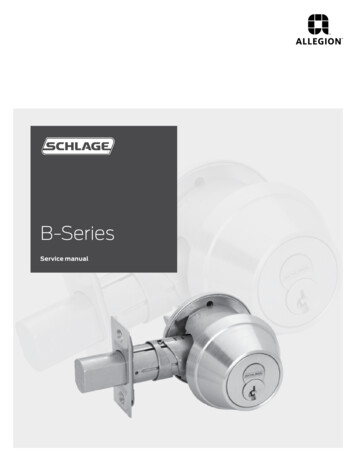
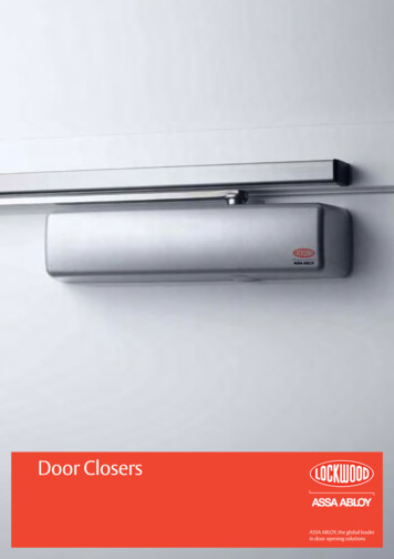
INSTALLATION INSTRUCTIONSPackage ContentsEntry keys (2 ea.)Interior AssemblyLatch (Adjustable)2-3/8” (60mm) to 2-3/4” (70mm)Mounting PlateExterior Assembly5/16” (8mm) Screws - 2 ea.3/4” (19mm) Screws - 5 ea.Strike Plate7/8” (22mm) Screws - 2 ea.1” (25mm) Screw - 1 ea.Tools RequiredTools Required for Installationon Pre-drilled Doors: Phillips ScrewdriverTools Required for Installationon Doors That Require Drilling: Drill Tape Measure Pencil 2-1/8” (54mm) Drill Hole Saw 1” (25mm) Drill 1/16” (2mm) Drill Chisel Hammer Phillips ScrewdriverDO NOT RETURN TO STORE! If any parts are missing or damaged,please call Customer Service toll free at 1-800-860-1677 Ext. 1801 (M-F 8am – 5pm PST)Page 1
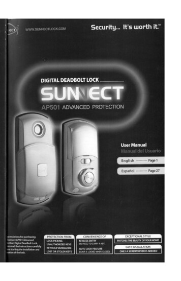
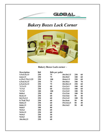
PREPARE DOOR AND JAMBNOTE: For installation on doors with pre-drilled holes skip to 4e.1. TEMPLATEa. Cut out template printed on page 15 of this Manual(Figure 1a).b. Fold template and place on door 36” (915mm) fromthe ground as marked (Figure 1b).2. MARK THE DOOR FOR DRILLINGb. Mark center hole on door edge through guide ontemplate for 1” (25mm) latch bolt (Figure 2a).a. Mark center hole on door face through guide ontemplate for 2-3/8” (60mm) or 2-3/4” (70mm)backset (Figure 2b).3. DRILL AND CHISEL DOORa. Drill 2-1/8” (54mm) hole through door face as markedfor lock set (Figure 3a).b. Drill 1” (25mm) hole in center of door edge forLatch (Figure 3b).c. Insert Latch in hole keeping it parallel toface of door. Mark outline and remove Latch(Figure 3c).d. Chisel 1/8” (3mm) deep or until latch face is flushwith door edge (Figure 3d).Figure 1aFigure 1bFigure 2aFigure 2bFigure 3aFigure 3bFigure 3cFigure 3dNOTE: For Drive in Latch, drill hole size indicated on template and pressuntil it is flush with door edge.4. MARK AND DRILL DOOR JAMBa. Mark center hole on edge of jamb even with the center of the Latch Bolt on dooredge. (Figure 4a).b. Drill 1” (25mm) hole 1-3/16” (30mm) deep in door jamb on center mark(Figure 4b).c. Outline outside edges of Strike Plate (Figure 4c).d. Chisel 1/8” (3mm) deep for Strike Plate or until flush (Figure 4d).e. Install Strike Plate using two 3/4” (19mm) screws provided (Figure 4e).Figure 4aFigure 4bFigure 4cFigure 4dFigure 4ePage 2
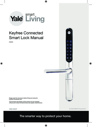
ADJUSTING LATCHNOTE: Latch is shipped with the backset set at 2-3/8” (60mm)Measure the backset (backset is distance between edge of the door and thecenter of Lock).TO CONVERT FROM 2-3/8” (60mm) BACKSET TO 2-3/4” (70mm) BACKSET2-3/8"(60mm )PULLTO CONVERT FROM 2-3/4” (70mm) BACKSET TO 2-3/8” (60mm) BACKSET2-3/4"(70mm)PUSHNOTE: Curved part of Latch always facescurved portion of Strike PlateINSTALLING LATCH5. INSTALLING THE LATCH (need phillips head screwdriver)a. Make sure the face plate sits flush with the door. Do not forcethe latch into the mortise flush. Chisel out excess material ifnecessary for a flush fit (Figure 5a).b. Using two 3/4” (19mm). screws provided, screw the latch into thedoor with a hand held screwdriver. DO NOT OVER TIGHTEN(Figure 5b).Figure 5aFigure 5bPage 3
INSTALLING EXTERIOR ASSEMBLY6. INSTALLING THE EXTERIOR ASSEMBLYNote: Work with the Door Open for easy access. To access the mounting plate, unpackthe Interior Assembly and remove the battery cover by sliding the cover upward. Locatethe screws holding the Mounting Plate to the Interior Assembly. Remove the screws torelease the Mounting Plate from the Interior Assembly.a. Unpack the Exterior Assembly. Use care to not scratch the green circuit boardduring handling and installation.b. Check that the Rubber Gasket is properly seated on the Exterior Assembly(Figure 6a-b).c. Insert the Exterior Assembly onto the door with the tailpiece going through theLatch spindle in the VERTICAL POSITION. Route the Control Wire throughthe door over the Latch (Figure ical)Figure 6a-bNOTE: Tailpiece must bepositioned verticallyFigure 6cMounting Plate7. SECURING THE EXTERIOR ASSEMBLY TO THE DOOR3/4” (19mm) screwa. From the side marked “This side against door”,(Optional Installation)route the Control Wire through the rectangularControl Wireslot in the Mounting Plate (Figure 7a).b. Place Mounting Plate against door with tailpiece passingthrough the center hole in the three hole set (Figure 7b).c. Secure the Mounting Plate to the Exterior Assembly using7/8” (22mm) screwstwo 7/8” (22mm) Screws (Figure 7c).Figure 7a-7fd. Hand tighten with a Phillips Screwdriver leaving looselyconnected (Figure 7d).e. Check that the Rubber Gasket is properly aligned and correct as necessary (Figure 7e).f. Check vertical alignment of the lock (Figure 7f).g. Tighten securely with a hand held Phillips Screwdriver. DO NOT OVER TIGHTEN8. OPTIONAL INSTALLATIONa. Using a 1/16” (2mm) drill bit, drill a pilot hole in your doorusing the Mounting Plate upper hole as a guide (Figure 8a).b. Insert one 3/4” (19mm) screw and tighten.Figure 8aNOTE: Rotate knob to ensure the latch is opening and closing easily.Page 4
INSTALLING INTERIOR ASSEMBLY9. ATTACH THE CONTROL WIRE TO THE INTERIOR ASSEMBLYa. Use care to attach the Control Wire male plug to the Interior Assembly femalesocket connector (Figure 9a).b. Do not force the Control Wire male plug into the Interior Assembly femalesocket connector (Figure 9b).c. The Control Wire male plug has two alignment tabs on the smooth side of theplug which is the top of the plug (Figure 9c).d. The Control Wire male plug is inserted with the smooth side up into the InteriorAssembly female socket connector (Figure 9d).Interior WireConnectorPlugFigure 9a-d10. ATTACH THE INTERIOR ASSEMBLY TO DOORa. Position the Interior Assembly over the tailpiece and push the Interior Assemblyagainst the door (Figure 10a).b. Using two 5/16” (8mm) screws and one 1” (25mm) screw, attachthe Interior Assembly to the Mounting Plate. DO NOT OVER TIGHTEN SCREWS(Figure 10b).5/16” (8mm) screws1” (25mm) screwFigure 10a-bNOTE: Lock and unlock using Interior Knob to see if thelatch is opening and closing easily.Page 5
INSTALLING INTERIOR ASSEMBLY (CONT.)11. Installing Batteriesa. Insert 4 AA high quality Alkaline batteries into the Battery Compartment in thedirection noted /- on the Compartment. The Lock will beep 2 times, the keypadwill illuminate blue, and the Honeywell button will flash green twice to signify thatit has received power (Figure 11a).NOTE: Do not touch the Keypad until the blue light turns off.Do not use rechargeable batteries or non-alkaline batteries.b. Slide the Battery Cover down into the track on the Interior Assembly to coverthe batteries (Figure 11b).Light IndicatorBatteryCoverKeypadOverrideAccess KeyExterior AssemblyInteriorKnobFigure 11a-bInterior Assembly12. Testing LockWith the Door Opena. Test the Lock using the Interior Knob. The Latch should move smoothly.b. Test the lock using the Keypad. To lock press and then press “ 1234”to unlock.INSTALLATION OVERVIEWBattery CoverInterior AssemblyStrike PlateOptional3/4” (19mm) screw5/16” (8mm) screwsMounting Plate3/4” (19mm) screws1” (25mm) Screw7/8” (22mm) screwsLatchKeysExteriorAssemblyTailpieceRubber GasketPage 6
OPERATION INSTRUCTIONSExterior Assembly OverviewIndicator lightGreen Indicates Successful Programming Step Indicates Unlocking is SuccessfulRed Indicates Failed Programming Step Indicates Locking is SuccessfulLock buttonLock - Used to lock doorClear - Used to clear wrong keypad entriesUnlock buttonUnlock - Used to unlock doorProgramming - Used in programming stepsBatteries (not included)Electronic lock requires (4) High QualityAA Alkaline batteries. When all 4 batteriesare installed in the correct position, hear 2beeps and the keypad will illuminate blue.DO NOT TOUCH the keypad until the keypadstops illuminating.Programming SymbolsLock / ClearUnlock / ProgrammingPC Programming CodeUC User Code (4-8 digits)ID User ID (01-50, 2 digits)Factory SettingsThe lock comes factory preset with a:PC Programming code - 123456UC User code - 1234ID User ID - 01Please change the ProgrammingCode PC and the User Code UCas soon as possible after installationto insure security.Programming Tips5 Seconds - Complete all the programming steps in the programming mode within 5 seconds.Clear - Use the key to clear entries in case a wrong button is pushed.Page 7
Locking and UnlockingTO UNLOCK THE LOCKUsing Keypad: Enter a valid User Code (default code is 1234) and press and hear1 beep and lights green.TO LOCK THE LOCKUsing Keypad: Press and then hear 2 beeps and lights red.Changing Programming CodeCHANGE CURRENT OR PRESET PROGRAMING CODE PCPCFactory default Programming Code 123456, this is the master password foryour lock. All programming functions require this code. Follow the below sequence toPCchange the Programming Code toyour custom 6 digit combination.PCPC4 new Re-enterPCHear 1 beep and Light Indicator illuminates green.Record New and Changed Codes on Programming Record located on Page 13.Adding User CodesTO ADD A NEW USER CODE (you can add up to 50 new user codes)UCUCThe User Code mustbe a 4-8 digit combination. Each User Code isthen linkedIDto a User ID (which is any number between 01-50) to identify an individual UserUC (User ID 1-9IDCode .should be entered as 01-09 so they are 2 digits).For example: to add the User ID - 08 to User Code - 5678, enter the following:PC123456UCID1 Re-enter08UC5678 5678Hear 1 beep and Light Indicator illuminates green.NOTE: When a NEW USER CODE is set, the default factory code (1234) is deletedfor safety.Record New and Changed Codes on Programming Record located on Page 13.Page 8
Deleting User CodesDELETE ONE EXISTING OR PRESET USER CODEUCIDThe unit comes with a factory User ID 01 for User Code 1234.UCUCIMPORTANT: To delete 1 User Code , the lock must have more than 1 User Codein its database.PC2 Existing IDre-enterIDHear 1 beep and Light Indicator illuminates green.DELETE ALL USER CODESIMPORTANT: this will delete the user codes but not the programming code, enterthe following.PC3 re-enterPCHear 1 beep and Light Indicator illuminates green.Automatic Lock FunctionSET OR CANCEL AUTO LOCKYou can set the lock to automatically close after each time the lock is opened. Timevalue range 20 - 900 seconds, enter the following:Set Auto Lock:PC5 Time ValueHear 1 beep and Light Indicator illuminates green.To cancel Auto Lock set the time to 00, enter the following:Cancel Time Value Auto Lock:PC5 00Hear 1 beep and Light Indicator illuminates green.Temporarily Disable Auto-LockDISABLE:PCWhile in Auto-Lock mode, unlock door using ,within 10 seconds you must turn thelocking knob by hand to the locked position, wait more than 2 seconds then turn thelocking knob back to the unlock position. The Auto-Lock mode is now disabled.RESTORE:To restore the Auto-Lock funtion, you can turn the locking knob by hand to the lockedposition, wait more than 2 seconds or press theLock button on the keypad.Page 9
Vacation ModeWith Vacation Mode enabled, the system enters into low-power comsumption mode.During this mode, all buttons and functions including the remote controll will be invaliduntil they are re-enabled (see steps below).ENABLE:PC101Hear 1 beep and Light Indicator illuminates green then lock doorDISABLE:To disable the Vacation Mode, you must press and hold for more than 3 seconds,PCthen input tounlock the door. Vacation Mode is now disabled.NOTE: If you only press thefor more than 3 seconds butdo not input PC , the system will remain in Vacation Mode.Secure Lock-out PeriodWarning sounds and LED flashes red after 4 incorrect code attempts: Keypad shutsdown for 30 seconds.Sound On and OffYou can “mute” or turn the “sound on” on your lock by entering the following.(Factory setting is sound on).PC6 1 or 21 Sound Off2 Sound OnSound Off (1) - Light Indicator illuminates green.Sound On (2) - Hear 1 beep and Light Indicator illuminates green.Restore Factory SettingsTo reset the lock to the original factory settings including the Programming Code PCUCand all User Codes removeone battery for 10 seconds. Reinsert the battery andwait for a long and short beep. Press 3 times within 3 seconds. The lock will beepand the light indicator will turn green.Low Battery WarningBeeps and LED flashes red for 5 seconds. Replace with good quality alkaline batteries.Note: Removing batteries does not erase active Programming or User Codes.Page 10
CONSUMER FRIENDLY MESSAGE GUIDEUnlock / Valid programming:1 long beep and LED illuminates greenLock:2 short beeps and LED illuminates redInvalid Programming:2 short beeps and LED flashes red twiceLow Voltage:Beeps for 5 seconds(7/9 times depends on operation is unlock/lock)Super Low Voltage:4 short beeps and LED flashes red four times4 Incorrect code entry attempts:2 short beeps and LED illuminates red each attemptPower on:1 long beep and 1 short beep and LED illuminates greenChip Reset:1 long beep and 1 short beep and LED illuminates green(may occur several times or once in a while)Lock Error:3 long beeps LED flashes red three timesRepeat operation after Lock Error:2 short beeps three times LED flashes red six timesNOTE: When battery is under low voltage, the lock will give the (Low Battery Warning: Beeps andLED flashes red for 5 seconds). During this time your lock can still work. However once the voltageis lower than 4.3V (called Super-Low Voltage), the operation of the locking and unlocking will notwork, user must replace batteries immediately.INSTALLATION TROUBLE SHOOTINGIssueSolutionLock will not functionelectronically Check that all batteries are fresh high qualityAlkaline Batteries Check for proper polarity ( -) of all batteries Check that the Control Wire is attached to theInterior AssemblyLatch is sticking.Installation screws of the lock may be too tight and have to beloosened Remove Interior Assembly Slightly loosen the Mounting Plate Screws Lock and unlock using the Key Reattach Control Wire and Interior AssemblyPage 11
CONSUMER ASSISTANCEEMAIL: LHLPCustomerService@LHLPinc.comWEBSITE: www.honeywellsafes.comADDRESS: Consumer Assistance Dept.LH Licensed Products, Inc., 860 East Sandhill Avenue Carson, CA 90746 USATELEPHONE: US/Canada 1-800-860-1677 Ext. 1801 (Toll Free)Mexico 01-800-288-2872 After English voice recording stops you must then enter 800860-1677 to complete your call. (Toll Free)Australia 0011-800-5325-7000 (Toll Free)Germany/New Zealand 00-800-5325-7000 (Toll Free)Other Countries XX*-310-323-5722 (Toll Charges Apply)XX*- Dial U.S. Country Code firstCALL CENTER HOURS: US/Canada 8am – 5pm (Pacific**) Mon – Fri(Subject to change)CALL BACK HOURS: Other Countries 8am – 5pm (Pacific**) Mon – Fri(Subject to change)* Insert correct Country Code** Local Time based on Los Angeles California USAINTERNATIONAL CALL BACK HOURS:If you need to speak with a consumer assistant and cannot contact us during the CallCenter hours above, please send an email or leave a telephone message, including yourName, Telephone Number and the best time for us to contact you during the Call Backhours above and we will make our every effort to contact you and help answer any ofyour questions or concerns.Page 12
Programming RecordMy Codes:Programming CodeDate Created(6 digits) / /User Code 01(4-8 digits) / /User Code 02(4-8 digits) / /User Code 03(4-8 digits) / /User Code 04(4-8 digits) / /User Code 05(4-8 digits) / /User Code 06(4-8 digits) / /User Code 07(4-8 digits) / /User Code 08(4-8 digits) / /User Code 09(4-8 digits) / /User Code 10(4-8 digits) / /User Code 11(4-8 digits) / /User Code 12(4-8 digits) / /User Code 13(4-8 digits) / /User Code 14(4-8 digits) / /User Code 15(4-8 digits) / /User Code 16(4-8 digits) / /User Code 17(4-8 digits) / /User Code 18(4-8 digits) / /User Code 19(4-8 digits) / /User Code 20(4-8 digits) / /User Code 21(4-8 digits) / /User Code 22(4-8 digits) / /User Code 23(4-8 digits) / /User Code 24(4-8 digits) / /User Code 25(4-8 digits) / /Page 13
Programming Record ContinuedMy Codes:Date CreatedUser Code 26(4-8 digits) / /User Code 27(4-8 digits) / /User Code 28(4-8 digits) / /User Code 29(4-8 digits) / /User Code 30(4-8 digits) / /User Code 31(4-8 digits) / /User Code 32(4-8 digits) / /User Code 33(4-8 digits) / /User Code 34(4-8 digits) / /User Code 35(4-8 digits) / /User Code 36(4-8 digits) / /User Code 37(4-8 digits) / /User Code 38(4-8 digits) / /User Code 39(4-8 digits) / /User Code 40(4-8 digits) / /User Code 41(4-8 digits) / /User Code 42(4-8 digits) / /User Code 43(4-8 digits) / /User Code 44(4-8 digits) / /User Code 45(4-8 digits) / /User Code 46(4-8 digits) / /User Code 47(4-8 digits) / /User Code 48(4-8 digits) / /User Code 49(4-8 digits) / /User Code 50(4-8 digits) / /Page 14
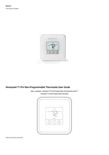
Page 15MARKFOR 1-3/8”(35mm)DOORTHEN DRILL 1” (25mm) HOLEIN CENTER DOOR OF EDGE2” (50mm) IN DEPTHMARKFOR 1-3/4”(45mm)DOORIMPORTANT!PLACE TEMPLATEON HIGH EDGE OFDOOR BEVEL2-3/4” (70mm) BACKSET2-3/8” (60mm) BACKSETPLACE TOP36” (915mm)ABOVE FLOORDRILL2-1/8” (54mm)HOLE
BACK OFTEMPLATEPage 16
Limited Lifetime Mechanical and Finish Warranty / 1 Year Limited Electronics WarrantyThis product comes with a limited lifetime mechanical and finish warranty and a one year limitedelectronics warranty to the original residential consumer against defects in material andworkmanship under normal use as long as the original residential purchaser occupies theresidential premises upon which the product was originally installed.ORIGINAL RESIDENTIAL CONSUMERThis warranty is not transferable, and applies to the original purchaser only, as long as the originalpurchaser occupies the residential premises upon which the product(s) was originally installed.Proof of purchase (original sales receipt) and ownership must accompany all warranty claims.All non-homeowner purchasers (including purchasers for industrial, commercial and business use)are not covered under the terms of this warranty.WHAT IS NOT COVEREDThis warranty is null and void if the product was used for purposes for which it was not designed.This warranty DOES NOT COVER normal wear and tear of parts or damage resulting from any ofthe following: negligent use, misuse or abuse of the product, or use contrary to or in violation ofwritten instructions provided by LH Licensed Products, Inc. Further, this warranty does not coverActs of God, such as fire, flood, hurricanes and tornadoes. This warranty DOES NOT COVERscratches, abrasions, deterioration due to the use of paints, solvents or use of cleanerscontaining abrasives, alcohol or other solvents, whether performed by a contractor, servicecompany, or yourself. This warranty DOES NOT COVER product(s) used in commercialapplications, used in common area applications, disassembly, repair or alteration by anyone otherthan LH Licensed Products, Inc., improper installation or exposure to extremes of heat or humidity.This warranty DOES NOT COVER any losses, injuries to persons or loss of property, generaldamages or costs, and shipping and freight expenses required to return product(s) toLH Licensed Products, Inc. LH Licensed Products, Inc. shall not be liable for any indirect,incidental or consequential damages of any nature relating to this lock. LH Licensed Products, Inc.is also not responsible for costs associated with removing or reinstalling the product.ADDITIONAL TERMSLH Licensed Products, Inc. does not authorize any person to create for it any obligation orliability in connection with the Product. LH Licensed Products, Inc.’s maximum liability hereunder is limited to the original purchase price of the Product. No action arising out of any claimedbreach of this warranty by LH Licensed Products, Inc. may be brought by the original residentialpurchaser more than one (1) year after the cause of action has arisen.Page 17
Manufactured by:LH Licensed Products, Inc.860 East Sandhill AvenueCarson, CA 90746The Honeywell Trademark is used under license from Honeywell International Inc. HoneywellInternational Inc. makes no representations or warranties with respect to this product.www.honeywellsafes.comPage 18
FRANÇAISGuide de configuration et d’utilisationCadenas électronique d’entrée avec boutonModèle 8732001, 8732101, 8732301, 8732401Veuillez lire ce manuel avec soin avantd’installer et d’utiliser ce produit!
SommaireINSTRUCTIONS D’INSTALLATIONContenu de l’emballage / Outils requis.Page 21Préparez la porte et le montant de porte.Page 22Ajustement du loquet/Installer le loquet.Page 23Installez l’ensemble extérieur.Page 24Installez l’ensemble intérieur.Page 25-26INSTRUCTIONS D’EMPLOIAperçu de l’ensemble extérieur.Page 27Verrouillage et déverrouillage / Modifier le code de programmation /Ajout de codes d’utilisateur.Page 28Supprimer les codes d’utilisateur / Fonction de verrouillage automatique /Désactiver temporairement le verrouillage automatique.Page 29Mode vacances / Période de « Lock out » sécurisée /Allumer et fermer le son / Paramètres réglés en usine /Avertissement de batterie faible.Page 30Guide de messages accessible à l’utilisateur / Dépannage.Page 31Aide au consommateur.Page 32Fiche de programmation.Page 33-34Du modèle.Page 35Garantie limitée.Page 37Page 20
INSTRUCTIONS D’INSTALLATIONContenu de l’emballageClé d’accès (2 ch.)Ensemble intérieurLoquet (ajustable) 60 mm(2-3/8 po) à 70 mm (2-3/4 po)Plaque de montageEnsemble extérieurGâcheVis de 5/16 po (8 mm) - 2 de chaqueVis de 7/8 po (22mm) - 2 de chaqueVis de 3/4 po (19 mm) - 5 de chaqueVis de 1” (25mm) Screw - 1 ea.Outils requisOutils requis pour l’installationsur les portes pré-percées : Tournevis PhillipsOutils requis pour l’installation surles portes qui exigent un perçage : Perceuse Ruban à mesurer Crayon Scie-cloche de 2-1/8 po (54 mm) Perceuse de 1 po (25 mm) Perceuse de 1/16 po (2 mm) Ciseau Marteau Tournevis PhillipsNE PAS RETOURNER AU MAGASIN! S’il manque des pièces ou si certaines sont endommagées, veuillezappeler le Service à la clientèle sans frais au 1-800-860-1677 Ext. 1801 (lundi au vendredi entre 8 h – 17 h HNP)Page 21
PRÉPAREZ LA PORTE ET LE MONTANT DE PORTEREMARQUE : Pour l’installation sur les portes avec des trouspréalablement percés, passez à la page 4.1. MODÈLEa. Découpez le modèle imprimé à la page 35 de ceManuel (Image 1a).b. Pliez le modèle et placez-le sur la porte à 36 po (915 mm)du du sol tel qu’indiqué par la marque (Image 1b).2. MARQUEZ LA PORTE POUR LE PERÇAGEb. Marquez le trou du centre sur le bord de la porte à traversle guide sur le modèle pour le boulon du loquet de 1 po(25 mm) (Image 2a).a. Marquez le trou du centre sur le devant de la porte à traversle guide sur le modèle pour une distance d’entrée de 2-3/8 po(60 mm) ou 2-3/4 po (70 mm) (Image 2b).3. PERCER ET BURINER LA PORTEa. Percez un trou de 2-1/8 po (54 mm) à travers le devant de laporte tel qu’indiqué pour le jeu de serrure (Image 3a).b. Percez un trou pour le loquet de 1 po (25 mm) aucentre du bord de la porte (image 3 b).c. Insérez le loquet dans le trou en le maintenantparallèle à la face de la porte. Marquez le contouret enlevez le loquet (image 3c).d. Taillez au ciseau environ 1/8 po (3 mm) de profondeur oubien jusqu’à ce que le devant du loquet soit à égalité avecle bord de la porte (Image 3d).Image 1aImage 1bImage 2aImage 2bImage 3aImage 3bImage 3cImage 3dREMARQUE : P our le verrou encastrable, percez la taille du trouindiquée sur le modèle et appuyez jusqu’à ce qu’il soit à égalité avec le bordde la porte.4. MARQUEZ ET PERCEZ LE MONTANT DE LA PORTEa. Marquez le trou du centre sur le bord du montant de la porte à égalité avec le centre duboulon du loquet sur le bord de la porte. (Image 4a).b. Percez un trou de 1 po (25 mm) à une profondeur de 1-3/16 po (30 mm) dans le montantde la porte sur la marque du centre (Image 4b).c. Délimitez les bords extérieurs de la Gâche (Image 4c).d. Taillez au ciseau environ 1/8 po (3 mm) de profondeur pour la Gâche ou bien jusqu’àégalité (Image 4d).e. Installez la Gâche en utilisant deux vis de 3/4 po (19 mm) fournies (Image 4e).Image 4aImage 4bImage 4cImage 4dImage 4ePage 22
AJUSTER LE LOQUETREMARQUE : Le loquet est expédié avec la distance d’entrée réglée à (60 mm) 2-3/8 poMesurez la distance d’entrée (la distance d’entrée est la distance entre le bord de laporte et le centre de la serrure).CONVERTIR DE LA DISTANCE D’ENTREÉ DE 2-3/4 po (60 mm) à LA DISTANCED’ENTRÉE DE 2-3/8 po (70 mm)2-3/8"(60mm )TIRERCONVERTIR DE LA DISTANCE D’ENTREÉ DE 2-3/4 po (70 mm) à LA DISTANCED’ENTRÉE DE 2-3/8 po (60 mm)2-3/4"(70mm)POUSSERREMARQUE : La partie courbée du loquetfait toujours face à la portion courbéede la gâcheINSTALLER LE LOQUET5. INSTALLER LE LOQUET (nécessite un tournevis Phillips)a. Assurez-vous que la plaque avant soit à égalité avec la porte. Nepas forcer le loquet dans la mortaise à égalité. Taillez au ciseaule matériel en excès, au besoin, afin d’obtenir un fini presqueencastré. (Image 5a).b. À l’aide des deux vis de 3/4 po (19 mm) fournies, vissez le loquetdans la porte avec le tournevis à main. NE PAS TROP SERRER(Image 5b).Image 5aImage 5bPage 23
INSTALLEZ L’ASSEMBLAGE EXTÉRIEUR6. INSTALLATION DE L’ENSEMBLE EXTÉRIEURRemarque : Travaillez avec la porte ouverte pour faciliter l’accès. Pour accéder à la plaquede montage, déballez l’assemblage intérieur et retirez le couvercle de la pile en glissant lecouvercle vers le haut. Localisez les vis maintenant la plaque de montage à l’assemblageintérieur. Retirez les vis pour dégager la plaque de montage de l’assemblage intérieur.a. Déballez l’ensemble extérieur. Prenez soin de ne pas égratigner le circuit vertpendant la manutention et l’installation.b. Vérifiez que le joint en caoutchouc est correctement attaché sur l’Ensemble extérieur(Image 6a-b).c. Insérez l’assemblage extérieur sur la porte avec le manchon passant à travers la tigedu loquet en POSITION VERTICALE. Passez le câble de commande à travers laporte, par-dessus le loquet à pêne dormant (image 6c).Câble decommandeJoint encaoutchoucManchon(Vertical)Image 6a-bTrou duloquetREMARQUE :Le manchon doit êtreen position verticaleImage 6cPlaque de montage7. FIXER L’ENSEMBLE EXTÉRIEUR À LA PORTEFacultatif Vis dea. Du côté marqué « Ce côté contre la porte »,3/4 po (19 mm)faites passer le Câble de commande à traversCâblede commandel’emplacement rectangulaire dans la Plaque demontage (Image 7a).b. Placez la Plaque de monta
TO UNLOCK THE LOCK Using Keypad: Enter a valid User Code (default code is 1234) and press and hear 1 beep and lights green. TO LOCK THE LOCK Using Keypad: Press and then hear 2 beeps and lights red. CHANGE CURRENT OR PRESET PROGRAMING CODE Factory default Programming Code 123456, this is the master password for your lock.