Transcription
BMD-360Stand-alone Bluetooth 5.1 low energy and IEEE 802.15.4moduleData sheetAbstractThis technical data sheet describes the BMD-360 stand-alone Bluetooth low energy and IEEE802.15.4 module. The OEMs can embed their own application on top of the integrated Bluetooth lowenergy stack using Nordic SDK integrated development environment (IDE).UBX-19039466 - R07C1-Publicwww.u-blox.com
BMD-360 - Data sheetDocument informationTitleBMD-360SubtitleStand-alone Bluetooth 5.1 low energy and IEEE 802.15.4 moduleDocument typeData sheetDocument numberUBX-19039466Revision and dateR07Disclosure restrictionC1-Public19-Jul-2021Product statusCorresponding content statusFunctional sampleDraftFor functional testing. Revised and supplementary data will be published later.In development /PrototypeObjective specificationTarget values. Revised and supplementary data will be published later.Engineering sampleAdvance informationData based on early testing. Revised and supplementary data will be published later.Initial productionEarly production informationData from product verification. Revised and supplementary data may be published later.Mass production /End of lifeProduction informationDocument contains the final product specification.This document applies to the following products:Product nameType numberIN/PCN referenceProduct statusBMD-360BMD-360-A-R-00N/AInitial productionBMD-360BMD-360-A-R-10UBX-20009871Initial productionBMD-360BMD-360-A-R-20UBX- 21028574Initial productionu-blox or third parties may hold intellectual property rights in the products, names, logos and designs included in thisdocument. Copying, reproduction, modification or disclosure to third parties of this document or any part thereof is onlypermitted with the express written permission of u-blox.The information contained herein is provided “as is” and u-blox assumes no liability for its use. No warranty, either express orimplied, is given, including but not limited to, with respect to the accuracy, correctness, reliability and fitness for a particularpurpose of the information. This document may be revised by u-blox at any time without notice. For the most recentdocuments, visit www.u-blox.com.Copyright u-blox AG.UBX-19039466 - R07C1-PublicDocument informationPage 2 of 32
BMD-360 - Data sheetContentsDocument information . 2Contents . 31Functional description . 51.1 Features . 51.2 Applications . 51.3 Block diagram . 61.4 Product specifications . 62Pin definition. 82.1 Pin assignment . 82.2 Peripheral pin assignments . 93Electrical specifications . 103.1 Absolute maximum ratings .103.2 Operating conditions .103.3 General purpose I/O .103.4 Module reset .113.5 Debug and programming.113.6 Clocks .1143.6.132.768 kHz crystal (LFXO) .113.6.232.768 kHz clock source comparison .12Firmware . 134.1 Factory image .134.2 Bluetooth low energy SoftDevices .134.3 IEEE 802.15.4 (Thread and Zigbee) .134.4 Bluetooth device address .145Mechanical specifications . 155.1 Dimensions .155.2 Recommended PCB land pads .155.3 Module marking .1665.3.1BMD-360-A-R-00 module marking .165.3.2BMD-360-A-R-10 and BMD-360-A-R-20 module markings .17RF design notes . 186.1 Recommended RF layout and ground plane.186.2 Mechanical enclosure .186.3 Antenna patterns.196.3.1X-Y plane .196.3.2X-Z plane.206.3.3Y-Z plane .207BMD-360 evaluation development kit . 218Qualification and approvals . 228.1 United States (FCC) .22UBX-19039466 - R07C1-PublicContentsPage 3 of 32
BMD-360 - Data sheet8.1.1Labeling and user information requirements .228.1.2RF exposure .238.2 Canada (ISED) .238.2.1Labeling and user information requirements .238.2.2RF exposure .248.3 European Union regulatory compliance .248.3.1Radio Equipment Directive (RED) 2014/53/EU .248.4 Australia / New Zealand (RCM) .248.5 Bluetooth qualification.249Environmental . 259.1 RoHS .259.2 REACH .259.3 California proposition 65 (P65) .2510 Product handling . 2610.1 Packaging .2610.1.1 BMD-360-A-R-00 reel packaging .2610.1.2 BMD-360-A-R-10 and BMD-360-A-R-20 reel packaging .2610.1.3 BMD-360-A-R-00 carrier tape dimensions.2710.1.4 BMD-360-A-R-10 and BMD-360-A-R-20 carrier tape dimensions .2710.2 Moisture sensitivity level .2810.3 Reflow soldering .2810.4 ESD precautions .2811 Ordering information . 2912 Life support and other high-risk warnings . 30Related documents . 31Revision history . 31Contact. 32UBX-19039466 - R07C1-PublicContentsPage 4 of 32
BMD-360 - Data sheet1Functional descriptionThe BMD-360 is a powerful, highly flexible, ultra-low power Bluetooth 5.1 and IEEE 802.15.4 (Threadand Zigbee) module based on the nRF52811 SoC from Nordic Semiconductor. With an Arm Cortex M4 CPU, embedded 2.4GHz transceiver, and integrated antenna, it provides a complete RF solutionwith no additional RF design, allowing faster time to market. Providing full use of the nRF52811’scapabilities and peripherals, the BMD-360 can power demanding applications, while simplifyingdesigns and reducing BOM costs. Angle of Arrival (AoA) and Angle of Departure (AoD) features ofBluetooth 5.1 are supported. With an internal DC-DC converter and intelligent power control, theBMD-360 provides class-leading power efficiency, enabling ultra-low power sensitive applications.Regulatory pre-approvals reduce the burden to enter the market. As a drop-in replacement for theBMD-300/301/330, the BMD-360 completes the BMD-300 Series lineup with an optimized peripheralset that is attractive for a wide range of cost-sensitive applications.1.1 Features Based on the Nordic Semiconductor nRF52811 SoCBluetooth 5.1 2M PHY, 1M PHY, Coded PHY (long range), CSA #2, AoA, AoDIEEE 802.15.4 with Thread and Zigbee supportComplete RF solution with an integrated DC-DC converterNordic Semiconductor SoftDevice readyOver-the-Air (OTA) firmware updatesNo external components requiredArm Cortex -M4 32-bit processor192 kB embedded flash memory24 kB RAM-40 C to 85 C Temperature Range32 General Purpose I/O Pins12-bit/200 KSPS ADCSerial Wire Debug (SWD)SPI Master/Slave (8 Mbps)2-wire Master/Slave (I2C compatible)Footprint compatible with BMD-300, BMD-301, BMD-330, BMD-340, and BMD-341UART (w/ CTS/RTS and DMA)Temperature sensor20 channel CPU independent Programmable Peripheral Interconnect (PPI)Quadrature Demodulator (QDEC)128-bit AES HW encryption3 x 32-bit Timer / Counter2 x 24-bit Real-Time Counter (RTC)Dimensions: 14 x 9.8 x 1.9mm1.2 Applications Beacons – iBeacon , Eddystone, AltBeacon, AoA, AoDLow-Power SensorsFitness devicesWearablesClimate ControlLightingSafety and SecurityHome AppliancesUBX-19039466 - R07C1-PublicFunctional descriptionPage 5 of 32
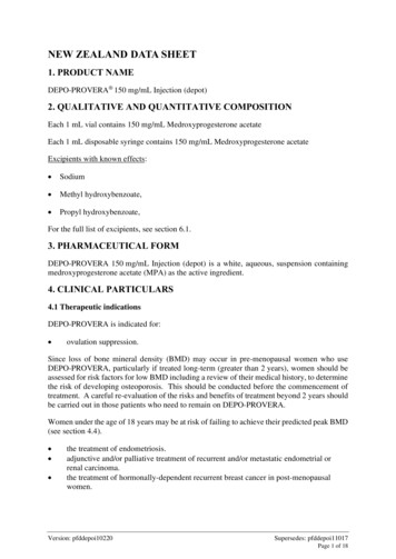
BMD-360 - Data sheet Access ControlInternet of ThingsHome Health CareAdvanced Remote ControlsSmart Energy ManagementLow-Power Sensor NetworksInteractive EntertainmentKey FobsEnvironmental MonitoringHotel AutomationOffice Automation1.3 Block diagramBMD-360 Bluetooth 5 Low Energy SoC ModulenRF52811-QFAx24kB RAMSWD Debug &ProgrammingCore LDODC/DC BuckRegulatorDC-DCInductorAccel AddressResolverARM Cortex-M4@ 64MHz2.4GHz RadioMulti-protocolAES ECBBalun192kBFlashMatchingNetworkAES CCM ModeEncryptionClockManagementReal TimeCounter x2WatchdogTimerTimer x3Random NumberGenTWIMasterSPIMasterUARTTWI SlaveSPI Slave4ch eripheralInterconnectTemperatureSensorGPIO TaskEvent h 12-bitADCPCBAntennaPDMGPIO x32(Analog x8)32 MHzCrystalFigure 1: Block diagram of BMD-3601.4 Product specificationsDetailDescriptionBluetoothBluetooth versionBluetooth 5.1 Low Energy, LE Coded PHY (Long Range), LE 2MPHY, LE 1M PHY, Advertising Extensions, CSA #2, AoA/AoDBluetooth securityAES-128LE connectionsConcurrent peripheral and broadcaster roles (S113)IEEE 802.15.4Thread stackOpenThread, Thread 1.1 compatibleThread securityAES-128Zigbee stackZigbee 3.0 compatibleRadioFrequencyUBX-19039466 - R07C1-Public2.360 GHz to 2.500 GHzFunctional descriptionPage 6 of 32
BMD-360 - Data sheetDetailDescriptionModulationsGFSK at 1 Mbps and 2 Mbps, QPSK at 250 KbpsTransmit power 4 dBm maximumReceiver sensitivity-97 dBm (Bluetooth low energy 1M mode), -104 dBm (CodedPHY mode)AntennaIntegrated (-1 dBi peak)Current consumptionTX only @ 4 dBm, 0 dBm @ 3V, DCDC enabled7.0 mA, 4.6 mATX only @ 4 dBm, 0 dBm15.4 mA, 10.1 mARX only @ 1 Mbps @ 3V, DCDC enabled4.6 mARX only @ 1 Mbps10.0 mARX only @ 2 Mbps @ 3V, DCDC enabled5.2 mARX only @ 2 Mbps11.2 mACPU @ 64 MHz from flash, from RAM4.2 mA, 4.0 mACPU @ 64 MHz from flash, from RAM @ 3 V, DCDC enabled2.2 mA, 2.1 mASystem Off, On0.3 µA, 0.6 µAAdditional current for RAM retention30 nA / 4 KB blockDimensionsBMD-360Length: 14.0 mm 0.3mmWidth: 9.8 mm 0.3mmHeight: 1.9 mm 0.1mmHardwareInterfacesSPI Master/Slave x 2UARTTwo-Wire Master/Slave (I2C)GPIO x 32PWMPDMPower supply1.7 V to 3.6 VTemperature range-40 C to 85 CCertificationsUSA (FCC)FCC part 15.247 modular certification FCC ID: XPYBMD360Canada (ISED)Innovation, Science and Economic Development Canada RSS247 modular certification IC: 8595A-BMD360Europe (CE)EN 62368-1:2014 A11:2017EN 62479:2010EN 301 489-1 V2.1.1EN 301 489-17 V3.2.0EN 300 328 V2.2.2Australia / New Zealand (RCM)AS/NZS 4268:2017, Radio equipment and systems – Shortrange devicesBluetoothBMD-360 RF-PHY Component (Tested) – DID: D040773;QDID: 95452Radio chipNordic Semiconductor nRF52811Additional details:nRF52811 Product Specification [3]nRF Connect SDK [4]nRF5 Software Development Kit [5]Table 1: Product specificationsUBX-19039466 - R07C1-PublicFunctional descriptionPage 7 of 32
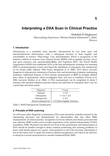
BMD-360 - Data sheet2Pin definition2.1 Pin assignmentBMD-360 shares an identical pin-out with BMD-300, BMD-301, and BMD-330. This pin-out is also asubset of the BMD-340/341 footprint, allowing a single design to support any of these modules.Figure 2: BMD-360 Pin assignment (Top view)No.NameI/ODescription1GNDPowerElectrical Ground2GNDPowerElectrical Ground3GNDPowerElectrical Ground4GNDPowerElectrical Ground5GNDPowerElectrical Ground6P0.25I/OGPIOP0.25Standard drive, low frequency I/O only7P0.26I/OGPIOP0.26Standard drive, low frequency I/O only8P0.27I/OGPIOP0.27Standard drive, low frequency I/O only9P0.28I/OGPIO/AIN4P0.28Pin is analog capable, standard drive, low frequency GPIO only10P0.29I/OGPIO/AIN5P0.29Pin is analog capable, standard drive, low frequency GPIO only11P0.30I/OGPIO/AIN6P0.30Pin is analog capable12P0.31I/OGPIO/AIN7P0.31Pin is analog capable13P0.00I/OGPIO/XTAL1(32.768 kHz)P0.0014P0.01I/OGPIO/XTAL2(32.768 kHz)P0.0115P0.02I/OGPIO/AIN0P0.02Pin is analog capable16GNDPowerElectrical Ground17VCCPower1.7 V to 3.6 VVDDAn internal 4.7 µF bulk capacitor is included on the module.However, it is good design practice to add additional bulkcapacitance as required for your application, i.e. those withheavy GPIO usage and/or current draw.18GNDPowerElectrical Ground19P0.03I/OGPIO/AIN1P0.03Pin is analog capable20P0.04I/OGPIO/AIN2P0.04Pin is analog capable21P0.05I/OGPIO/AIN3P0.05Pin is analog capable22P0.06I/OGPIOP0.06UBX-19039466 - R07C1-PublicnRF52 pin RemarksPin definitionPage 8 of 32
BMD-360 - Data sheetNo.NameI/ODescriptionnRF52 pin 1128P0.12I/OGPIOP0.1229GNDPowerElectrical Ground30GNDPowerElectrical PIOP0.2039P0.21I/OGPIO/RESET 4I/OGPIOP0.2443SWCLKISWD ClockSWDCLK44SWDIOI/OSWD IOSWDIO45GNDPowerElectrical Ground46GNDPowerElectrical Ground47GNDPowerElectrical GroundTable 2: BMD-360 pin-out2.2 Peripheral pin assignmentsThe peripherals within the BMD-360 may be assigned to nearly any of the GPIO pins through theapplication. There are some restrictions called out by the nRF52811 product specification. See theRemarks in Table 2. Also note that certain peripherals are assigned to particular pins, such theanalog inputs. Only one peripheral signal can be multiplexed to a GPIO pin at a time. Trace signals, analog inputs,XTAL signals, SWD interface, and reset are restricted to certain pins due to additional internalcircuitry required by the interface. See Table 3.PeripheralSignalPin OptionsUART0, I2C0, SPI0, SPI1, PDM, PWM0AllP0.00-P0.31ADC, COMP, LPCOMPAllP0.02-P0.05, P0.28-P0.31 (AIN0-AIN7)ResetRESET NP0.21SWDSWD ClockSWD IOSWCLKSWDIO32.768 kHz CrystalXTAL1XTAL2P0.00P0.01Table 3: Peripheral pin optionsUBX-19039466 - R07C1-PublicPin definitionPage 9 of 32
BMD-360 - Data sheet3Electrical specifications Stressing the device above one or more of the Absolute maximum ratings may cause permanentdamage. These are stress ratings only. Operating the module at these or at any conditions otherthan those specified in the Operating conditions should be avoided. Exposure to absolutemaximum rating conditions for extended periods can also affect device reliability. Operating condition ranges define those limits within which the functionality of the device isguaranteed. Where application information is given, it is advisory only and does not form part ofthe specification.3.1 Absolute maximum ratingsSymbolDescriptionMinMaxUnitVCC MAXVoltage on supply pin 0.33.9VVIO MAXVoltage on GPIO pins (VCC 3.6V) 0.33.9VVIO MAXVoltage on GPIO pins (VCC 3.6V) 0.3VCC V0.3 VTSStorage Temperature Range 40125 CTable 4: Absolute maximum ratings The product is not protected against overvoltage or reversed voltages. If necessary, voltage spikesexceeding the power supply voltage specification, given in table above, must be limited to valueswithin the specified boundaries by using appropriate protection devices.3.2 Operating conditions Unless otherwise specified, all operating condition specifications are at an ambient temperatureof 25 C and a supply voltage of 3.3 V. Operation beyond the specified operating conditions is not recommended and extended exposurebeyond them may affect device ing supplyvoltage1.73.03.6VTR VCCSupply rise time (0V to 1.7 V)--60msTAOperating Ambient 40TemperatureRange2585 CTable 5: Operating conditions3.3 General purpose I/OThe general purpose I/O is organized as one port enabling access and control of the 32 available GPIOpins via one port. Each GPIO can be accessed with the following user configurable features: Input/output directionOutput drive strengthInternal pull-up and pull-down resistorsWake-up from high- or low-level triggers on all pinsTrigger interrupt on all pinsUBX-19039466 - R07C1-PublicElectrical specificationsPage 10 of 32
BMD-360 - Data sheet All pins can be used by the PPI task/event system; the maximum number of pins that can beinterfaced through the PPI at the same time is limited by the number of GPIOTE channelsAll pins can be individually configured to carry serial interface or quadrature demodulator signalsSymbolParameterMin.Typ.Max.UnitVIHInput High Voltage0.7 x VCC-VCCVVILInput Low VoltageGND-0.3 x VCCVVOHOutput High VoltageVCC 0.4-VCCVVOLOutput Low VoltageGND-GND 0.4VRPUPull-up Resistance111316kΩRPDPull-down Resistance111316kΩTable 6: GPIO electrical specifications3.4 Module resetGPIO pin P0.21 may be used for a hardware reset. In order to utilize P0.21 as a hardware reset, theUICR registers PSELRESET[0] and PSELRESET[1] must be set alike, to the value of 0x7FFFFF15.When P0.21 is programmed as RESET, the internal pull-up is automatically enabled. NordicSemiconductor example applications and development kits program P0.21 as RESET.3.5 Debug and programmingThe BMD-360 series supports the two pin Serial Wire Debug (SWD) interface and offers flexible andpowerful mechanism for non-intrusive debugging of program code. Breakpoints, single stepping, andinstruction trace capture of code execution flow are supported.3.6 ClocksThe BMD-360 requires two clocks, a high frequency clock and a low frequency clock.The high frequency clock is provided on-module by a high-accuracy 32 MHz crystal as required by thenRF52811 for radio operation.The low frequency clock can be provided internally by an RC oscillator or synthesized from the fastclock, or externally by a 32.768 kHz crystal. An external crystal provides the lowest powerconsumption and greatest accuracy. Using the internal RC oscillator with calibration providesacceptable performance for Bluetooth low energy applications at a reduced cost and slight increasein power consumption.3.6.132.768 kHz crystal (LFXO)SymbolParameterTyp.Max.UnitFNOM LFXOCrystal frequency32.768-kHzFTOL LFXO BLEFrequency tolerance, Bluetooth low energyapplications1- 250ppmFTOL LFXO ANTFrequency tolerance, ANT applications1- 50ppmCL LFXOLoad Capacitance-12.5pFC0 LFXOShunt Capacitance-2pFRS LFXOEquivalent series resistance-100kΩCpinInput Capacitance on XL1 & XL2 pads4-pFfTOL LFXO BLE and fTOL LFXO ANT are the maximum allowed for Bluetooth low energy applications. Actual tolerance depends on thecrystal used.1UBX-19039466 - R07C1-PublicElectrical specificationsPage 11 of 32
BMD-360 - Data sheetTable 7: 32.768 kHz crystal (LFXO)3.6.232.768 kHz clock source comparisonSymbolParameterMin. Typ.Max.UnitION RAM OFF RTC LFXOSystem ON with 32.768 kHz Crystal Oscillator-1.0-µAION RAM OFF RTCCurrent for 32.768 kHz RC Oscillator-1.4-µAf TOL LFRCFrequency Tolerance, 32.768 kHz RC Oscillator-- 5%fTOL CAL LFRCFrequency tolerance, 32.768 kHz RC after calibration-- 500ppmfTOL LFSYNTFrequency Tolerance, 32.768 kHz Synthesized Oscillator-- 48ppmTable 8: 32.768 kHz clock source comparisonUBX-19039466 - R07C1-PublicElectrical specificationsPage 12 of 32
BMD-360 - Data sheet4FirmwareProjects for the BMD-360 should utilize the Nordic Semiconductor nRF Connect SDK [4] and thenRF52811 tools for new development. The tools allow access to the very latest Bluetooth supportfrom Nordic Semiconductor and provide an ongoing path as new features are released.The nRF5 SDK [5] can also be used if the feature set of the SDK meets the application requirements.4.1 Factory imageThe BMD-360 module is not loaded with a factory firmware image.4.2 Bluetooth low energy SoftDevicesNordic Semiconductor protocol stacks for Bluetooth low energy are known as SoftDevices.SoftDevices are pre-compiled, pre-linked binary files. SoftDevices can be programmed in nRF52 seriesSoCs and are downloadable from the Nordic Semiconductor website.The S113 SoftDevice is a Bluetooth low energy peripheral protocol stack solution. It supports up tofour peripheral connections with an additional broadcaster role running concurrently. The S113SoftDevice integrates a Bluetooth low energy Controller and Host and provides a full and flexible APIfor building Bluetooth low energy nRF52 System on Chip (SoC) solutions.4.3 IEEE 802.15.4 (Thread and Zigbee)IEEE 802.15.4 based protocols on BMD-360, such as Thread and Zigbee, are not implemented usinga SoftDevice. Nordic Semiconductor provide pre-compiled Thread and Zigbee stacks and an IEEE802.15.4 compliant MAC stack, which does not require a SoftDevice to be loaded to operate. Bothallow for concurrent operation with Bluetooth low energy SoftDevices.For more information about developing applications that utilize IEEE 802.15, see also reference [4].UBX-19039466 - R07C1-PublicFirmwarePage 13 of 32
BMD-360 - Data sheet4.4 Bluetooth device addressThe BMD-360 modules are preprogrammed from the factory with a unique public Bluetooth device(MAC) address stored in the CUSTOMER[0] and CUSTOMER[1] registers of the User InformationConfiguration Registers (UICR). The Bluetooth device address consists of the IEEE OrganizationallyUnique Identifier (OUI) combined with the six hexadecimal digits that are printed on a 2D barcode andin human-readable text on the module label, as described in Module marking. The Bluetooth deviceaddress is stored in little endian format. The most significant bytes of the CUSTOMER[1] register are0xFF to complete the 32-bit register.UICR 1080Bluetooth addr [0] (0xFF)Example value. Actual value printed on labelCUSTOMER[0]0x10001081Bluetooth addr [1] (0xEE) Example value. Actual value printed on labelCUSTOMER[0]0x10001082Bluetooth addr [2] (0xDD) Example value. Actual value printed on labelCUSTOMER[0]0x10001083Bluetooth addr [3] (0xCC) IEEE OUI2,3CUSTOMER[1]0x10001084Bluetooth addr [4] (0xBB) IEEE OUI2,3CUSTOMER[1]0x10001085Bluetooth addr [5] (0xAA) IEEE 100010870xFFUnusedTable 9: Bluetooth device addressThe IEEE OUI for type number BMD-360-A-R-00 is: 94:54:93. The second half of the full Bluetooth device address is encodedin the label data matrix. The full Bluetooth device address is stored in the UICR.3Type numbers BMD-360-A-R-10 and BMD-360-A-R-20 encode the full Bluetooth device address in the label data matrix andis stored in the UICR.2UBX-19039466 - R07C1-PublicFirmwarePage 14 of 32
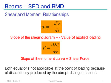
BMD-360 - Data sheet5Mechanical specifications5.1 DimensionsLength: 0.3 mm, Width: 0.3 mm, Height: 0.1 mmFigure 3: BMD-360 mechanical drawing5.2 Recommended PCB land padsFigure 4: Recommended PCB land pads The RF Keep-out area extends vertically to the board edge.UBX-19039466 - R07C1-PublicMechanical specificationsPage 15 of 32
BMD-360 - Data sheet5.3 Module marking5.3.1BMD-360-A-R-00 module markingFigure 5 illustrates the label of the BMD-360 modules, which includes the u-blox logo, product name,Bluetooth address, and certification numbers.124Figure 5: Module marking for type number BMD-360-A-R-003ReferenceDescription1Data Matrix with unique serial number of six alphanumeric symbols, also in human-readable form. The fullBluetooth address consists of the IEEE OUI (94:54:93) with the six symbols appended: Example value:94:54:93:AA:BB:CC2Last characters of type number: BMD-360-A-R-003FCC and ISED (IC) Certification IDs4Product nameTable 10: BMD-360 label description for type number BMD-360-A-R-00UBX-19039466 - R07C1-PublicMechanical specificationsPage 16 of 32
BMD-3
BMD-360 - Data sheet UBX-19039466 - R07 Document information Page 2 of 32 C1-Public Document information Title BMD-360 Subtitle Stand-alone Bluetooth 5.1 low energy and IEEE 802.15.4 module Document type Data sheet Document number UBX-19039466 Revision and date R07 19-Jul-2021 Disclosure restriction C1-Public Product status Corresponding content status