Transcription
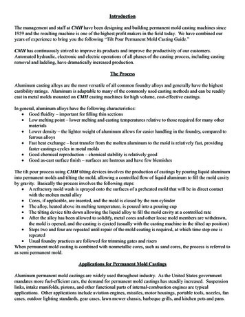
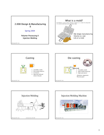
What is a mold?From Webster: a cavity in which a substance is shaped: as (1) : a matrix for casting metal(2) : a form in which food is given a decorative shape2.008 Design & ManufacturingIISpring 2004-Net shape manufacturing-Volume vs. cost-Life of a moldPolymer Processing IIInjection Molding2.008-spring-2004 S. Kim12.008-spring-2004 S. KimCasting1.2.3.4.Die castingAssemble a mold.Pour molten metal in.Cool down.Open the mold andremove the part.2.008-spring-2004 S. Kim1. Assemble a mold2. Inject molten metal into3. Open and removealuminum, magnesiumPrecision parts3Injection Molding2.008-spring-2004 S. Kima slide from B. Kim, 1982, MIT22.008-spring-2004 S. Kim4Injection Molding Machine52.008-spring-2004 S. Kim61
Injection Cycle TimeSteps of Injection Molding– – Typical Cycle of Injection Molding Mold Close1-2 secInjection2-5 secPack and Hold 8-10 secPart Cool10-20 sec– Screw return2-5 sec Mold open1 sec Ejection1 sec-Mold closing-Filling, packing, holding-Cooling-Opening, part removal.2.008-spring-2004 S. Kim7 Part designMoldableDraft angleShrinkageReinforcements (ribs and bosses)Cycle timeAppearance (defects)flashPmaxPoorquality Mold DesignPmin– Gate– balancing Process Control2.008-spring-2004 S. Kim9GoodBetter weldDegradationburnLow cost shortshotTminTmax2.008-spring-2004 S. Kim10Short shotFlashesFlashes develop at the mold parting line or ejector pin installation point. It is aphenomenon where molten polymer smears out and sticks to the gap.CausePoor quality of the mold. The molten polymer has too low viscosity.Injection pressure is too high, or clamping force is too weak.SolutionAvoiding excessive difference in thickness is most effective.Slow down the injection speed.Apply well-balanced pressure to the mold to get consistent clamping force, orincrease the clamping force.Enhance the surface quality of the parting lines, ejector pins and holes.2.008-spring-2004 S. Kim8Injection molding processwindowDesign for Manufacturing––––––2.008-spring-2004 S. Kim11This is the phenomenon where molten plastics does not fill the mold cavitycompletely. and the portion of parts becomes incomplete shape.CauseThe shot volume or injection pressure is not sufficient.Injection speed is so slow that the molten plastics becomes solid before itflows to the end of the mold.SolutionApply higher injection pressure. Install air vent or degassing device. Changethe shape of the mold or gate position for better flow of the plastics.2.008-spring-2004 S. Kim122
Injection Molding ParametersPlasticating Extrusion Temperature and Pressure: Function (x,y,z) Melt Temperature Control– Through Cylinder(Barrel) Frictional Heating Heating bands for 3 zones– Rear zone– Center zone (10F-20F hotter)– Front Zone (10F-20F hotter) Nozzlesmoothsurfaceroughsurface2.008-spring-2004 S. Kim132.008-spring-2004 S. KimTemperature CycleSuggested Melt Temp at nozzle Acetal (coploymer)400Acrylic425ABS400Liquid Crystal Polymer500Nylon 50Polyetheretherketone720Polyethylene LDPE325Polyethylene HDPE350Polypropylene350Polystyrene350Thermoplastic polyester (PBT) 425Urethane elastomer425FFFFFFFFFFFFFFF2.008-spring-2004 S. Kim1516 Mold Temperature Control– Mold cooling with water, oil.– Hot mold for less residual stresses (orientation)-Flow path ratio is the ratio between L (the distance between the gate andthe farthest point in the molding dimension) and T (the thickness of thepart) .-When molding large or thin parts, the flow path ratio is calculated todetermine if molten plastics can fill the mold cavity. Low thermal inertia– Uneven cooling warpage, twisting, shrinkage defects Shrinkage can progress for up to 30 days.Polyethylene (PE)L/T 280-100Polypropylene (PP)L/T 280-150Polyvinyl chloride (PVC) L/T 280-70Polystyrene (PS)L/T 300-220Polycarbonate (PC)L/T 160-90Acrylonitrile butadienstylene(ABS)L/T 280-120Polyamide (PA)L/T 320-200Rule of thumb2.008-spring-2004 S. KimMold Temperature ControlFlow path ratio2.008-spring-2004 S. Kim14172.008-spring-2004 S. Kim183
Mold coolingWarpageMolding cycle can be shortened by reducing time for cooling andsolidification of molten plastics.Solidification time, tthickness2/α,This deformation appears when the part is removed from the mold andpressure is released.thermal diffusitivityWarpage or stress in a part can be generated when mold shrinkagevaries due to different thickness, leading internal residual stressdifference.CauseUneven shrinkage due to the mold temperature difference (surfacetemperature difference at cavity and core), and the thickness difference inthe part. Injection pressure was too low and insufficient packing.Even coolingSolutionTake a longer cooling time and lower the ejection speed. Adjust the ejectorpin position or enlarge the draft angle. Examine the part thickness ordimension. Balance cooling lines. Increase packing pressure.2.008-spring-2004 S. Kim192.008-spring-2004 S. KimPressure Control20Pressure Control pressure distribution Injection unit– Initial injection pressure Applied to the molten plastic and resulting from the mainhydraulic pressure pushing against the back end of theinjection screw (or plunger).– Packing pressure– Injection Pressure inside mold Usually 1,000 psi to 5,000 psi Lower than hold and pack pressure between 10,000psi and20,000 psiEnd of filling2.008-spring-2004 S. Kim212.008-spring-2004 S. KimPressure Control22Clamp force– Hold pressure (packing) Compensate shrinkage Rule of thumb: Hold pressure 150% of injectionpressure. Applied at the end of the initial injection stroke, and isintended to complete the final filling of the mold andhold pressure till gate closure Pressure Required– Total force projected area times injection pressure (A X P)– Rule of thumb 4 to 5 tons/in2 can be used for most plastics.– Example, Part is 10 in by 10 in by 1 in Projected area Surface area 10 in x 10 in 100 in2 Injection Pressure 15,000 psi for PC Tonnage required to keep mold closed is– 100 in2 x 15,000 psi 1,500,000 lbs 750 tons (note : 2000lbs 1 ton)10 inParting line ?2.008-spring-2004 S. Kim232.008-spring-2004 S. Kim10 in244
Mold Structure - Cavity and coreMold Structure: Parting lineA dividing line between a cavity plate and a core plate of amold.- Make a parting line on a flat or simple-curved surface so thatflash cannot be generated.- Venting gas or air.2.008-spring-2004 S. Kim252.008-spring-2004 S. Kim26DeliveryMold Structure: Undercut, Slide coreSprueA sprue is a channel through which totransfer molten plastics injected from theinjector nozzle into the mold.RunnerA runner is a channel that guides moltenplastics into the cavity of a mold.GateA gate is an entrance through whichmolten plastics enters the cavity.2.008-spring-2004 S. Kim272.008-spring-2004 S. KimTwo plate mold28Three plate moldOne parting lineTwo parting lines2.008-spring-2004 S. Kim292.008-spring-2004 S. Kim305
Runner balancingRunner cross sectionRunner cross section that minimizes liquid resistanceand temperature reduction when molten plastics flowsinto the cavity.balanced- Too big- Longer cooling time, more material, cost- Too small- short shot, sink mark, bad quality- Too long- pressure drop, waste, coolingNot balancedHot runner, runnerless mold2.008-spring-2004 S. Kim312.008-spring-2004 S. KimGate32Fan gate, Film gate, Direct gate-Restricts the flow and the direction of moltenplastics.-Quickly cools and solidifies to avoid backflowafter molten plastics has filled up in the cavity.-Simplifies cutting of a runner and moldings tosimple finishing of parts.Side gate2.008-spring-2004 S. KimSubmarine gate332.008-spring-2004 S. KimGate Positioning34Molecular orientationPoint 1: Set a gate position where molten plastics finish filling upin each cavity simultaneously. Same as multiple points gate.Gate 1Gate 2Point 2: Basically set a gate position to the thickest area of a part.This can avoid sink marks due to molding (part) shrinkage .Point 3: Set a gate position to an unexposed area of part or wherefinishing process can be easily done.Point 4: Consider degasing, weldline, molecular orientation.Point5: Fill up molten plastics using the wall surface in order not togenerate jetting.Die swell Thickness, tCCt2.008-spring-2004 S. Kim35CCCCC2.008-spring-2004 S. KimCCCσCCCσ366
Draft angleDesign for Manufacturing -for removing parts from the mold- 1-2o, material, dimension, texture dependent- Cavity side smaller, core side larger.- Crystalline material has more shrinkage.- Amorphous material has smaller shrinkage.Moldable: flow path ratio, machine sizeDraft angleShrinkageReinforcements (ribs and bosses)Cycle timeAppearance, defectsBalance, balance, balance!!2.008-spring-2004 S. Kim372.008-spring-2004 S. KimRibs and BossesShrinkage L α L T α Tα: shrinkage rate38Resin NameMolding Shrinkage (%)Polyethylene (PE)1.5-6.0Polypropylene (PP)1.0-3.0Polyvinyl chloride (PVC)0.1-0.5Polystyrene (PS)0.2-0.6Polycarbonate (PC)0.5-0.8Acrylonitrile butadienstylene0.3-0.8Polyamide (PA)0.6-2.02.008-spring-2004 S. Kim392.008-spring-2004 S. Kim402.008-spring-2004 S. Kim412.008-spring-2004 S. Kim427
DefectsSink marksMolding defects are caused by related and complicatedreasons as follows:* Malfunctions of molding machine* Inappropriate molding conditions* Flaws in product and mold design* Improper Selection of molding material-Equal cooling from the surface-Secondary flow-Collapsed surfaceÆSink Mark2.008-spring-2004 S. Kim432.008-spring-2004 S. KimWhitening44WeldlineThis is a phenomenon where a thin line is created when different flows ofmolten plastics in a mold cavity meet and remain undissolved. It is a boundarybetween flows caused by incomplete dissolution of molten plastics. It oftendevelops around the far edge of the gate.After the ejection by the ejector pin, the surface of the ejected part orsurrounding part turns white. When some portion of the part is hard to removefrom the mold, that portion also turns white.CauseLow temperature of the mold causes incomplete dissolution of the moltenplastics.CauseThe part was hard to remove from the mold. Poor quality of the mold surfaceSolutionIncrease injection speed and raise the mold temperature. Lower the moltenplastics temperature and increase the injection pressure. Change the gateposition and the flow of molten plastics. Change the gate position to preventdevelopment of weldline.SolutionPolish the mold well to facilitate removal of the part. Lower the injectionpressure to facilitate removal of the part Reduce the ejector pin speed, andincrease the number of ejector pins.2.008-spring-2004 S. Kim452.008-spring-2004 S. KimJetting46Flow markThis is the phenomenon where the part has a wire-shape flow pattern on thesurface.CauseDue to inappropriate gate position, a flow of molten plastics into the cavity iscooled in a line shape and remains undissolved with other plastics flowcoming later.SolutionRaise the molten plastics and mold temperature, and increase injectionspeed to make the initial and later flows of molten plastics dissolvecompletely. Change the gate position to make the molten plastics touch thefacing side before making a line shape.This is a phenomenon where the initial flow of molten plastics which solidifiesmixes with a later flow and remains undissolved. It develops distinctivepatterns such as clouds, scales or tree rings.CauseInjection speed is too fast.Mold or molten plastics temperature is too low.SolutionEnlarge the gate area to decrease the speed of the molten plastics flowingthrough the gate.Increase the pressure retention time for better pressure quality.tDie swell Thickness, t2.008-spring-2004 S. Kim472.008-spring-2004 S. Kim488
What is a mold?-Net shape manufacturing-Volume vs. cost-Life of a mold From Webster: a cavity in which a substance is shaped: as (1) : a matrix for casting metal (2) : a form in which food is given a decorative shape 2.008-spring-2004 S. Kim 3 Casting 1. Assemble a mold. 2. Pour molten metal in. 3. Cool down. 4. Open the mold and remove the part.