Transcription
700IEEE Transactions on Consumer Electronics, Vol. 50, No. 2, MAY 2004Adaptive Transmission Control for Error-ResilientMultimedia SynchronizationChia-Chen Kuo, Guo-Shiang Ma, Ming-Syan Chen, Fellow, IEEE, and Jeng-Chun ChenAbstract — Multimedia streams impose tight temporalconstraints since different kinds of continuous multimediastreams have to be played synchronously. We devise in thispaper an adaptive transmission scheme to ensure the errorresilient and synchronous playback of audio and videostreams based on the Real-time Transport Protocol.Realization of our adaptive transmission control iscomposed of a series of operations in three stages, namely,(1) dynamic reordering mechanism, (2) error-resilientmechanism, and (3) adaptive synchronization mechanism.In this paper, an empirical study is conducted to provideinsights into our adaptive transmission scheme. Asvalidated by our performance study, the adaptivetransmission mechanism is able to strike a good balance ofboth stable playback and the end-to-end delay reduction.Furthermore, we analyze the jitter resistance, the end-toend delay, and video quality in order to enhance theapplicability of this scheme to more applications thatrequire the transmission of multimedia data.achieve a reordered and synchronous playback by properlyassigning the presentation time. However, the trade-off isthe increased end-to-end delay and the buffer size required.How to minimize the delay is an important issue inmultimedia synchronization. There have been varioussynchronization techniques proposed [5], [8], [12], [16].Although prior works have employed adaptive schemes,most of them concentrated on single media continuity anddid not deal with incoming Real-time Transport Protocol(RTP) [13] or error-resilient issues. To remedy this, wedevelop in this paper an adaptive transmission schemebased on RTP that is not only able to resist the inter-arrivaljitters and the skew between audio and video streams butalso able to minimize the end-to-end delay adaptively. Inaddition, our scheme consists of dynamic reordering anderror-resilient mechanism which are both essential inimproving the Quality of Service (QoS) of the multimediatransmission [10].Index Terms — Multimedia synchronization, errorresilient, jitter resistanceI. INTRODUCTIONMultimedia transmission requires the integration ofdifferent types of media streams. A temporal relationshipexists among the information of these distinct streams.Multimedia systems must maintain the mutual relationshipfor proper data transmission and presentation. The processof maintaining the temporal relationship of one or severalmedia streams is referred to as multimedia synchronization[6], [7]. Advances in communication technology lead tonew applications in the areas of multimedia networking.Increased bandwidth of the network has made it feasible toprovide various multimedia services, including video ondemand, video conferencing, and distance learning, toname a few. These applications typically integrate differenttypes of media objects, and the end clients of these servicesreceive multimedia streams through the network forplayback. Due to unreliable characteristics of the packetswitched network, the implementation of synchronizationmechanism is deemed challenging [3], [9].Fig. 1 illustrates the possibility of network jitters andpacket out-of-orders lead to the network delay. Althoughthe source sends out packets periodically, the incomingpackets arrive at unpredictable time slots. Through thebuffering mechanism of the receiver, it is possible toContributed PaperManuscript received March 3, 2004Fig. 1. The possibilities of end-to-end delay resulted from networkjitters and packet out-of-ordersRealization of our adaptive scheme is composed of aseries of operations in three stages, namely, (1) dynamicreordering mechanism, (2) error-resilient mechanism, and(3) adaptive synchronization mechanism. The first stagereorders the packets and sends them to the second stageupon its completion. It is so designed that only out-of-orderpackets incur extra processing delay. The second stagedecodes the payload data which is then pushed to the thirdstage. In the meanwhile, a proper error-resilient algorithmis selected according to the network status to recover thepossibly lost packets. The encoder can encode input videosequences according to variable channel error situationswhen a separate backward channel is available for thedecoder to send packet loss reports. The most attractivefeature is that error propagation can be completely removedsoon at the decoder even without succeeding full INTRAcoded frames. When sufficient memory resources are0098 3063/04/ 20.00 2004 IEEEAuthorized licensed use limited to: National Taiwan University. Downloaded on January 16, 2009 at 01:59 from IEEE Xplore. Restrictions apply.
C.-C. Kuo et al.: Adaptive Transmission Control for Error-Resilient Multimedia Synchronizationavailable at the encoder, it can encode frames using someprevious correctly decoded frames for reference, thusremoving error propagation at the decoder.In the third stage, the adaptive synchronizationmechanism is realized by adjusting the queuing lengthadaptively. This is the very significant part to achieveadaptive synchronization in our transmission scheme. Thequeue accumulates a certain amount of data beforeplayback in order to resist inter-arrival jitters and variancesof the end-to-end transmission delay. In addition, bycomparing timestamp fields of audio and video streams, wecan identify the matching audio and video slices forsynchronous playback. Another important benefit of thismechanism is that no matter how much processing delaydoes the reordering and error-resilient algorithms ofprevious stages spend, our adaptive synchronizationalgorithm is able to control the queuing length precisely toeliminate the time-based skew between the audio and videostreams and minimize the end-to-end delay. This designmakes it feasible to improve the reordering and errorresilient algorithms independently or even change thedecoding codecs or error-resilient methods dynamicallywithout affecting the audio and video synchronizationafterward.This paper is organized as follows. The system modeland involved standards are described in Section II. Theadaptive transmission scheme for error-resilient multimediasynchronization is developed in Section III. In addition, theperformance study is presented in Section IV. Finally, thispaper concludes with Section V.II. PRELIMINARYTo validate our adaptive transmission control for errorresilient multimedia synchronization, we develop an ITU-TH.323 [2] compliant videoconferencing application with afocus on highly interactive conferences. In order toimprove the error resiliency, this software application takesadvantage of two-way communication mechanisms such asacknowledgments of correctly received packets viabackward channel messages. Considering the clarity ofperformance evaluation, we introduce error concealmenttechniques for video communications to elucidate ourtransmission scheme. Our adaptive transmission schemecan be utilized on other error concealment techniques [4],[11] for audio and video communications. Since each errorconcealment algorithm has its advantages anddisadvantages with regard to the time complexity, thebuffer size, and the recovery quality, we can dynamicallyswitch to the suitable algorithm depending on packet lossfraction reported from RTCP [14]. While the networkstatus is good enough, the error concealment is not requiredand the resources consumption, such as the CPU power, the701memory space, and the processing delay can thus bereduced.A. Error-Resilient Video CommunicationPacket losses can severely degrade the quality of futuredecoded pictures at the decoder since an IP packet usuallycarries an integer number of macroblock (MB) rows.Obviously it is not sufficient to just apply URecommendation H.245 [1] allows the encoder anddecoder to build an out-of-band channel on which thedecoder can return packet loss information. To exploit thisfeature, our design makes good use of a connectionoriented data channel. Upon backward channel messagessent from the decoder, the encoder can take into accountthe packet loss and encode either severely damaged MBs inINTRA mode or less affected MBs in INTER mode.Fig. 2. Transmission model of error-resilient video communicationAs shown in Fig. 2, the out-of-band channel is used as aseparate backward channel for adaptive error concealment.Since it is built upon TCP sockets, all backward messagescan reach the encoder in order and remain intact. Thesession management is responsible for passing thesemessages to its forward video channel. Then the encoderprocesses all received back-channel messages before a newinput video frame is to be encoded. This technique has twooperation modes, i.e., NACK and ACK modes. As will beseen later, the NACK mode is preferred when packet lossrate is low since it places little burden on the outputbandwidth. The ACK mode works better at high packet lossrates since a single packet loss only affects one frame.B. Real-time Transport ProtocolReal-time Transport Protocol (RTP) [13] has beendesigned within the Internet Engineering Task Force(IETF). The data part of RTP is a thin protocol providingthe support for applications with real-time properties,including timing reconstruction, loss detection, security,and content identification. RTP header contains thefollowing information.Authorized licensed use limited to: National Taiwan University. Downloaded on January 16, 2009 at 01:59 from IEEE Xplore. Restrictions apply.
702IEEE Transactions on Consumer Electronics, Vol. 50, No. 2, MAY 2004Payload type: A one-byte payload type identifies thekind of payload contained in the packet, e.g., H.263 videoor G.723 audio.Timestamp: A 32-bit timestamp describes thegeneration instant of the data contained in the packet. Thefrequency clock of timestamp depends on the payload type.We can slice one video frame into several packets with thesame timestamp and order them by consecutive sequencenumbers.Sequence number: A 16-bit packet sequence numberallows loss detection and reordering within a series ofpackets with the step-up sequence numbers.Other fields are not described here in the interest ofbrevity. Depending on these fields, RTP provides deliveryservices for information with real-time characteristics, suchas interactive audio and video communication. As weknow, UDP, the well-handled transport protocol on IPbased network, does not ensure the orderly transmission ofpackets. Due to unreliable characteristics of the packetswitched network, the packet loss, data out-of-order andinter-arrival jitters may occur [6]-[8], [16]. RTP providesscores of useful information for the synchronization amongmedia streams of different types. The incremental sequencenumber is used for reordering and the judgment of packetloss. By comparing the differences of timestamps betweenmedia objects, we decide the playback instants with clockprecision for the purpose of synchronization. In addition,we are capable of compensating lost packets by audio andvideo error-resilient algorithms in order to improve theQoS.Fig. 3. Three stages of proposed adaptive transmission controlIII. ADAPTIVE TRANSMISSION CONTROLThe adaptive transmission scheme we developed consistsof three stages, namely, (1) dynamic reorderingmechanism, (2) error-resilient mechanism, and (3) adaptivesynchronization mechanism. As shown in Fig. 3, the firststage reorders packets received from the network and sendsthem to the second stage. After decoding and recoveringthe payload data, media objects are pushed into the thirdstage and played synchronously according to our adaptivealgorithm. The details of these three stages are described inthe following subsections.A. Dynamic Reordering MechanismDynamic reordering mechanism invokes a certainamount of buffer which accumulates packets beforeforwarding them to the next stage. At the same time, itreorders the packets according to the sequence number fieldin order to reduce the occurrences of packet out-of-order toa certain degree depending on the buffer size. In addition, ifthe packet which should arrive on time is not receivedbefore the time it is supposed to be passed to the next stage,we treat such a situation as a packet loss no matter itencounters a real loss or just a short-run delay. Note thatsuch kind of packets can be recovered in the next stage.In order to put each incoming packet with a sequencenumber, we apply a circular data structure on the reorderingbuffer. Assuming that our system provides the buffer size N,we take the sequence number n of incoming packets anddivide by N to get the remainder n mod N in order todecide the position for each packet. The procedure ofdynamic reordering, abbreviated as DR, is described below.Procedure DR: procedure of dynamic reorderingStep 1: Initialize all slots of the reordering buffer.Step 2: Assuming that the sequence number of the firstpacket is m, we set an expected sequence number E asm 1 and immediately send to the next stage a repackagedpacket with the necessary information, including thesequence number, the timestamp, the payload type and thepayload data. The expected number E is an indicator todecide the operation for each incoming packet by checkingtheir sequence numbers.Step 3: Wait for the next incoming packet. Oncereceiving the new packet, check its sequence number n.Step 3.1: If n is smaller than E, it implies that the packetis obsolete. Skip this packet and return to Step 3.Step 3.2: If n equals to E, meaning that this packet iswhat we expect, we check the slots from n mod N to n N1 mod N of the reordering buffer sequentially until weencounter an empty slot. If slot k mod N ( n k n N 1 )is not empty, pop out the repackaged packet to the nextstage and set E as k 1. Otherwise stop the checkingprocess and then return to Step 3. This step will flush outall continuous packets starting from n.Step 3.3: If n falls between E and E N, it implies thatthe packet we expect has not arrived yet. We shall wait forthe expected packet to reorder incoming packets. Thus, westore the necessary information of the incoming packet inslot n mod N and then return to Step 3.Step 3.4: If n is equal to or larger than E N, it impliesthat the packet we expect has not arrived yet. However, inthis case we cannot wait any longer because of the bufferoverflow. Hence, we treat these packets with sequencenumber from E to n-N as lost packet and clear correlativeslots. In addition, we store the necessary information of thisincoming packet in slot n mod N. Finally, check the slotsfrom n-N 1 mod N to n mod N of the reordering buffersequentially until we encounter an empty slot. If slot k modN ( n N 1 k N ) is not empty, pop out the repackagedAuthorized licensed use limited to: National Taiwan University. Downloaded on January 16, 2009 at 01:59 from IEEE Xplore. Restrictions apply.
C.-C. Kuo et al.: Adaptive Transmission Control for Error-Resilient Multimedia Synchronizationpacket to the next stage and set E as k 1. Otherwise stopthe checking process and return to Step 3.By procedure DR, the buffer accumulates dynamicallyonly if incoming packets encounter the situation of packetout-of-order or packet loss. If incoming packets arereceived sequentially, we can pass them to the next stage intime without any extra processing delay. Note that thebuffer size N affects the worse case of end-to-end delay. Itis unnecessary to set N too high to overspend the memoryspace.703reference for the period of one round trip delay. It is worthmentioned that the decoder requires only one additionalframe buffer in NACK operation mode. If the round tripdelay is short, which is assumed to be one of the errorcharacteristics of LANs, the impact of packet losses at thedecoder can be removed after an acceptable period of time.The advantage of this mechanism over simple INTRAupdates lies in the increased coding efficiency.B. Error-Resilient MechanismWhile no packet loss is present during videotransmission, the encoder can always successfully encodedata with the expected coding efficiency. However, whenthe encoder does not know that some packets did not reachthe other end; subsequent decoded frames will suffer fromdegradation in visual quality due to predictive coding. WithNACK or ACK messages from the decoder, the encodercan react to them right away to eliminate error propagationat the decoder.NACK Mode: operation of low packet loss rateWhen operating in the NACK mode without any packetloss, the decoder keeps sending backward acknowledgmentmessages for the encoder to maintain frame buffers. Bychecking the TR (Temporal Reference) field in an ACKmessage, the encoder can then safely release frame buffersprior to the acknowledged frame. The best codingefficiency is maintained since the time lag between thereference frame and the current one is always one frameinterval. After a packet loss, the decoder sends an NACKwith the RTR (Requested Temporal Reference) field set tothe temporal reference of some previous correctly decodedframe kept at the decoder. Upon the receipt of this NACKmessage, the encoder then encodes data using the decoder'srequested frame for reference. The TRP (TemporalReference for Prediction) field in our modified RFC 2032[15] header is set to the RTR value in this NACK messageto inform the decoder which backup frame is used forreference.When a transmission error occurs, the decoder sendsthrough the backward channel a negative acknowledgmentmessage to inform the encoder. Consider the executionscenario in Fig. 4 as an example. In Fig. 4, assume thatframe 3 cannot be correctly decoded. The decoder thenbacks up frame 2 into its additional frame buffer and sendsbackward NACK(3, 2) requesting the encoder to use frame2 for reference. On receipt of an NACK for frame 3 beforethe encoding of frame 7, the encoder can therefore useframe 2 for reference and free the memory resources forframe 3 through frame 6 since these frames are all corruptat the decoder. Until the encoded data of frame 7 arrives,the decoder suffers from using inconsistent frames forFig. 4. Illustration of operation in the NACK modeACK Mode: operation of high packet loss rateWhen operated in the ACK mode, the decoder sendsACK messages to acknowledge all correctly decodedframes and the encoder uses for reference only therequested frame indicated in the back-channel message.The coding performance is lower even when notransmission errors occur since the time lag between thereference frame and the current frame is more than oneround trip delay. However, error propagation can beavoided entirely since only acknowledged frames are usedfor reference.Consider the execution scenario in Fig. 5 as an example.The decoder acknowledges and backs up every correctlydecoded frame until an error occurs to frame 4. Since frame5 is encoded using frame 1 for reference, the decoder canstill correctly decode frame 5 in reference to its backupframe 1 without any error propagated from corrupt frame 4.It is worth mentioned that no succeeding frames would bein reference to frame 4. The decoder can thus avoid errorpropagation after the error to frame 4 entirely. When thedecoder receives data for frame 6, it can safely free theframe buffer for frame 1 and use frame 2 for reference. Toreduce the number of additional frame buffer at the decoderby half, every two ACK messages could request the sameprevious reference frame. It is noted that sufficient previousframes at the encoder are required to cover the maximumround trip delay of NACK and ACK messages. However,the number of additional frame buffers at the decoder canbe reduced to one in the NACK mode. Storage reduction byhalf is possible in the ACK mode at the cost of slightlyincreased bit rates.Authorized licensed use limited to: National Taiwan University. Downloaded on January 16, 2009 at 01:59 from IEEE Xplore. Restrictions apply.
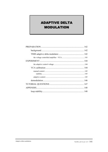
704Fig. 5. Illustration of operation in the ACK modeC. Adaptive Synchronization MechanismThe adaptive synchronization mechanism is realized byadjusting the queuing length adaptively. As mentionedearlier, this is the very significant part to achieve adaptivesynchronization in our transmission scheme. The queueaccumulates a certain amount of data before playback inorder to resist inter-arrival jitters and variances of the endto-end transmission delay. By comparing timestamp fieldsof audio and video streams, we can identify the matchingaudio and video slices for synchronous playback.We define TS(An) and TS(Vm) as the timestamps ofaudio and video streams with the incoming orders being nand m, respectively. The unit of timestamp depends on theclock frequency of the payload type defined in RFC1890[14]. Generally speaking, the audio is based on 8KHz andthe video is based on 90KHz. From the first incoming data,we get the timestamp as original TS(A0) and TS(V0).Therefore, TS(An)-TS(A0) and TS(Vm)-TS(V0) divided bytheir clock frequency CF(A) or CF(V) of the media typerepresents the distance of actual playback time from thefirst packet. By comparing with the presentation time of theaudio PT(An) [TS(An)-TS(A0)]/CF(A) and that of thevideo PT(Vm) [TS(Vm)-TS(V0)]/CF(V), we are able todetermine the precise playback time of audio and videobased on global timer in order to achieve synchronization.The procedure of global timer synchronization (abbreviatedas GTS) is described below.Procedure GTS: procedure of synchronization based onthe global timerStep 1: We define the playback queuing lengths of audioand video as QL(A) and QL(V), respectively, and wait forthe queuing lengths to reach the values of QLAinit andQLVinit. The system starts to check and pop out thequeuing data until both QL(A0) QLAinit and QL(V0) QLVinit.Step 2: We set a global timer which checks the status ofaudio and video buffers frequently with a polling period Pwhich is selected to be shorter than the arrival interval ofIEEE Transactions on Consumer Electronics, Vol. 50, No. 2, MAY 2004packets. The shorter the P, the more precise thesynchronization will be and the more system overhead willbe incurred. The global timer GT, the presentation time ofaudio PT(A0), and the video PT(V0) are all set to zerosinitially.Step 3: Wait for the polling instant with period P, andthen check the presentation time PT(An) and PT(Vm) ofpackets in front of the queue. In addition. We keep thevalue of minimal queuing length of both audio and video asQLAmin and QLVmim, respectively. If the current QL(A) QLAmin, we set QLAmin QL(A) to update the minimalvalue. Similarly, if QL(V) QLVmin, we set QLVmin QL(V). If the audio or video queue is underflow with zeroqueuing length, restart from Step 3. If the underflow occurscontinuously, it implies that a severe problem occurs due tonetwork lag or even disconnection. In such a condition, wereset the synchronization mechanism.Step 3.1: If PT(An) or PT(Vm) is equal to or larger thanGT P/2, it implies that it is not yet the time to play theaudio or video data. In this case, simply return to Step 3.Step 3.2: If PT(An) or PT(Vm) falls between GT-P/2and GT P/2, it implies that it is the time to play the audioor video data. Pop out the audio or video data, send them tothe playback device, and then return to Step 3.Step 3.3: If PT(An) or PT(Vm) is equal to or smallerthan GT-P/2, it implies that it is too late to play the audioor video data. Skip and flush audio or video data, and thencheck the next packet until the presentation time fallsbetween GT-P/2 and GT P/2 or the buffer underflow.Return to Step 3.Because both audio and video streams are based onidentical global timer GT, it is ensured that the audio andvideo will be synchronously played out by procedure GTS.In addition, by considering the arrival skew between audioand video and variances of the end-to-end delay, we controlthe queuing length and playback speed in order to increasethe stability of playback and minimize the end-to-end delay.In every polling instant, we get the values of queuinglengths QL(A) and QL(V). It can be seen that the value ofqueuing length will vary in a certain range because ofunpredictable inter-arrival jitters and network delays, andthe threshold of queuing length dominates the end-to-enddelay and jitter resistance. Our goal is to minimize theaverage queuing length while maintaining mediasynchronization and stable playback. Thus we canminimize the end-to-end delay depending on the networkstatus. The concept is depicted in Fig. 6.Authorized licensed use limited to: National Taiwan University. Downloaded on January 16, 2009 at 01:59 from IEEE Xplore. Restrictions apply.
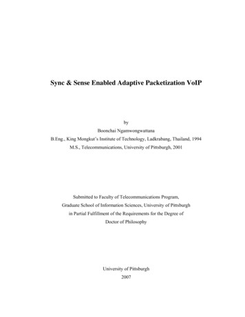
C.-C. Kuo et al.: Adaptive Transmission Control for Error-Resilient Multimedia SynchronizationFig. 6. Concept of adaptive synchronization mechanismAccording to the global timer, we check the status ofminimal queuing lengths QLAmin and QLVmin frequentlywith certain periods. These periods of adaptivemodifications should be longer than the polling period Pfor good stability. The procedure of adaptivesynchronization to minimize the end-to-end delay(abbreviated as ASMD) is described below.procedureofProcedureASMD:synchronization to minimize end-to-end delay705Clearly, the expected average delay time is Jitter(x)/2. Inaddition, if x TS/CF, packets can be out of order.As mentioned above, we implemented a module torealize the adaptive transmission scheme. This moduleconsists of the first stage which invokes procedure DR andthe third stage including procedures GTS and ASMD. Thevariance of arrival jitters will validate the adaptability ofour transmission scheme. We set the buffer size of dynamicreordering buffer to 3 and set an initial value of queuinglength for both QLAinit and QLVinit to 5. Because the arrivalfrequency of audio (20 samples/s) is larger than video (15frames/s), the queuing length of the audio is longer thanthat of the video on the average from the starting point.The synchronization module accepts and analyzes thepackets generated from the packet generation module. Weset the checking period, every 10 seconds, to modify theglobal timer according to procedure ASMD. In themeantime, the system maintains the average queuing lengthas it proceeds. The results are shown below.adaptiveStep 1: If QLAmin 2 and QLVmin 2, set GT GT Pin order to advance the playback instant and reduce theend-to-end delay.Step 2: If QLAmin 0 or QLVmin 0 which stands forthe buffer underflow, set GT GT-P in order to postponethe playback instant to avoid buffer underflow.Step 3: Reset QLAmin and QLVmin for next evaluation ofthe minimal queuing length.Procedure ASMD keeps the shorter queuing lengthbetween audio and video to one and avoids possibleoscillations which decrease the system stability.IV. PERFORMANCE STUDYTo evaluate the performance of our adaptivetransmission scheme, we conduct an empirical study toprovide insights into our scheme. We developed a softwaremodule of packet generation which is capable of simulatingvarious network conditions.A. Evaluation of End-to-End DelayIn this system, we define the values of related parametersof RTP packets as follows.Audio: CF(A) 8000 and TS(An) n*400 (20 samples/s)Video: CF(V) 90000 and TS(Vm) m*6000 (15frames/s)Polling Period: P 20 ms is selected, which is smallerthan the arrival interval of audio and video.Evaluated packets are generated sequentially with avariable delay interval to simulate the network jitters andpossible packet out-of-order conditions. We define thearrival time of packets as TS/CF Jitter(x) seconds. Jitter(x)is a random time value within the range 0 Jitter(x) x.Fig. 7. Average queuing lengths are minimized as time advancedFig. 7 shows the trend of average queuing lengthaccording to different jitter variances. It is worth mentionedthat the length is reduced to a stable value as time advances.A shorter queuing length corresponds to a shorter end-toend delay. As shown in Fig. 8, larger jitters require morebuffering spaces to avoid the buffer underflow. Dependingon the network conditions, our transmission scheme is ableto minimize the delay adaptively as well as to preserve astable playback. As validated by our empirical results, theQoS is improved prominently and our adaptivetransmission scheme is flexible to apply to comprehensiveapplications.Authorized licensed use limited to: National Taiwan University. Downloaded on January 16, 2009 at 01:59 from IEEE Xplore. Restrictions apply.
706Fig. 8. The impact of jitter to queuing lengthsB. Evaluation of Video QualityWe select the H.261 codec to incorporate error-resiliencemechanisms since it is more suitable for our frame-basedexperiment and also the bandwidth is not our main concernbecause our target network environment is local areanetworks. Our proposed mechanism is in fact applicable todifferent video coding standards as long as the RTPpayload-specific header format and back-channel messageformat are available.To simulate real-time video conferencing, our systemencodes the first 800 frames of a standard videophonesequence (Mother and Daughter) in the QCIF format. Thisvideo sequence has little motion in it and the backgroundscene does not change frequently as in a videoconferencing setting. We conducted two sets ofexperiments where one set is in the NACK mode and theother in the ACK mode. Each set has four different packetloss rates so as to observe the impact of packet loss. Thesame packet loss patterns are used in both sets for fairperformance comparison.The video channel of our H.323 videoconferencingapplication feeds the H.261 codec 15 input video framesevery second. Each frame is first encoded and packetizedinto three packets on a GOB basis. A modified RFC 2032[15] header is prefixed to each packetized data packet. Thevideo channel then passes all packets to its RTP module forreal-time transmission. Bit r
Realization of our adaptive transmission control is composed of a series of operations in three stages, namely, (1) dynamic reordering mechanism, (2) error-resilient mechanism, and (3) adaptive synchronization mechanism. In this paper, an empirical study is conducted to provide insights into our adaptive transmission scheme. As