Transcription
Operation ManualH6000 Series
ForewordThank you for purchasing Benchmark Scientific’s Incu-Mixer MP. Thisuser manual contains all pertinent information concerning the function andoperation of the instrument. In order to use the instrument properly, pleaseread this manual carefully before operation. Please keep for later referenceUnpacking and Pre-InstallmentPlease check the instrument and appendix against the packing list uponreceipt. If you find there is something wrong or missing, please contactBenchmark Scientific immediately.Safety Warnings and Guidelines1. Important information regarding operation:Please read and understand this manual completely prior to operation.Do not use the instrument without reading this instructionmanual. Read the guidelines and directions below and use theinstrument accordingly.2. Security:The operation, maintenance and repair of the Instrument should comply withthe basic guidelines and warnings listed below. Noncompliance may result indamage to the product and/or bodily harm to the user.This product a 115V electrical instrument suitable for indoor use.ReadtheManual carefullycarefully operatethisInstrument.equipment can operate this ricians should configure internal wiring.The operator should not open or repair the instrument. Thismay void any warranty, written or promised. In the event ofproduct failure, please contact Benchmark Scientific.
A.C. power’s grounding should be reliable to safeguardagainst an electric shock. The 3-pin plug supplied withincu-mixer’s power cable is a safety device that should bematched with a suitable grounded socket.During normal operation, the temperature of the heating blockwill be very high, and will cause injury. Please avoid personalcontact with the heat block while it is on.Close all tube lids before placing the tubes into the block. Heatedliquids may escape their vessels. Spilled liquids may causeinternal damage to the instrument.Before powering on, please confirm the that the electricaloutput of the instrument matches the outlet. If the electric line isdamaged, you should replace it with an identical line. Please besure there is nothing on the electrical line and avoid placing theline in a pedestrian thoroughfare. Hold the jack when you pull outthe electric line; do not pull the cord itselfThe Instrument should be put in the placed in a cool, dust freeenvironment, away from direct sunlight. In addition, theenvironment should have good ventilation, lack corrosive gasesor strong disturbing magnetic field, and be located far away fromany central heat source. Do not place instrument where it may besubjected to moisture. The vent on the Instrument is designed forventilation. Do not cover the vent, or the instrument may overheat. Please be sure to leave at least 100cm between theinstrument and other instrument or wall.Main power switch is on the rear of the device. Push“I” to power on the device, and push “O” to power offthe device.Power off when you finish your work. Disconnect the powersupply and cover the instrument with a cloth when not in usedfor extended periods of time.
Pull the plug from the jack immediately and contact thevendor if the following occurs: There is liquid flowing into the Instrument; Subjected to liquid or fire damage. Abnormal operation: such as abnormal sound or smell. Instrument drop or outer shell damage. Any other change to normal operation.3. Instrument MaintenanceThe heating plate should be cleaned on a regular basis with a soft cloth andalcohol to prevent variance in heat translation. Contamination on the plate maycause abnormal smell, smoke, and poor heat transfer.Power off when cleaning the Instrument.When cleaning the heating plate, do not douse r submerge in liquid.Corrosive cleaning solution may damage the instrument.
ContentsChapter 1 ------------------------1Chapter 2 -----------------------21 The normal operating --22 The basic parameters and r 3 -----------------------31 Structure -------------------32 Keyboard and Display ---43 Key ---------------------------5Chapter 4 Operation -----------61 Temperature, Speed and Time set-----------------------------------------62 Run, Pause and Stop ---73 Instantaneous Mixing ---74 Installing micro test plates -8Chapter 5 Failure analysis and troubleshooting----------------------------9Annex 1 Wiring Diagram of H6000 Incu-Mixer-----------------------------10
Incu-Mixer Operations ManualChapter 1 IntroductionChapter 1 IntroductionThe Incu-Mixer for micro plates is designed to shake and heat 2 or 4 standard,96-well micro plates.Features of this product are as follows:1) Microprocessor controlled time, speed and temperature2) Simultaneous display of set and actual time, temperature and shaking speed3) Audio signal and cessation of shaking motion after program completion4) Heating platform for standard micro test plate5) Soft start, easy to setup and use 1
Incu-Mixer Operations ManualChapter 2 SpecificationsChapter 2 Specifications1. Normal operating condition:Ambient temperature: 5 C 30 CRelative humidity: 70%Power supply:AC115V 50-60Hz2. The basic parameters and performanceModelIncu-MixerParameterMixing rate100 1500 rpmOrbit2mmTemperature rangeRT 5 C 70 CTiming range1min 99h59min 0.5 CAccuracy of the temperatureHeating time 25min (From room temperature to 70 C)Standard Block2 or 4 micro test platesDimension (mm)350(D) 320(W) 185(H)Net weight (kg)9.0 2
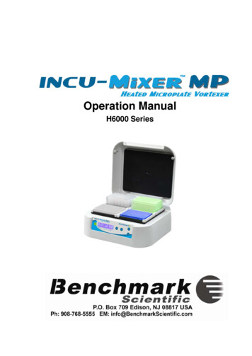
Incu-Mixer Operations ManualChapter 3 PreparationsChapter 3 PreparationThis chapter introduces the Incu-Mixer’s mechanical structure, the keyboardand key function, as well as preparations to make before power-on. You should befully familiar with this chapter before the Incu-Mixer is first operated。1. Structure DescriptionHot lidHeating PlateKeyboardPower connectorPower SwitchUniversal Serial Bus 3
Incu-Mixer Operations ManualChapter 3 Preparations2. Keyboard and Display panelDisplay Panel:Current temperatureCurrent speedRemnant timeP: 60.1150110:30S: 60.0150015:00Setting temperatureSetting speed 4 Setting time
Incu-Mixer Operations ManualChapter 3 Preparations3. Key FunctionsOFFStop temperature, speed or time functionSETSetting key, used together with “ ” and “ ” to set thetemperature , speed and timeSTOP/STARTStop/start key. Press this key to stop or start theprocedure. Press momentarily to start, Pressingcontinuously to stop. Increase key for temperature, speed or time Decrease key for temperature, speed or time 5
Incu-Mixer Operations ManualChapter 4 Operation guideChapter 4 Operation Guide1. Temperature, speed and time seta) The LCD will display the message to the rightwhen the instrument powers on. InitializationSystem-Testing.will be indicated by an audio signal.b) About 6s later, P line will display: 25.5 is theheating block’s current temperature; 0 is thecurrent speed; 00:00 is the current remnantP: 25.5S: 37.00150000:0010:00P: 25.5S: 60.00100000:0020:00time. S line will display: 37.0 is the former settemperature; 1500 is the former set speed;10:00 is the former set time.c) Press “SET” key momentarily. Then look atthe “S:” line. A cursor “ ” will appear. Use or to change the digital indicator above thecursor. Press “SET” key again to save thechange. (for example: shown to the right theinstrument is set such that the currenttemperature is 25.5ºC , the set temperature is60ºC; the current speed is 0 rpm, the setspeed is 1000 rpm; and the set mixing time is20h.d) If you want to shut off temperature function,press “SET” and move the cursor “ ” to thetemperature colum. Press “OFF” key and thetemperaturecolumnwilldisplay“OFF”.Function is similar for speed and timeoperations.— 6 —P: 25.5S: OFF0100000:0020:00
Incu-Mixer Operations ManualChapter 4 Operation guideNotes: 1) When time is set to “OFF”, the instrument functions continuously.2) Temperature, speed and time can not be set to “OFF” simultaneously3) The instrument will start to heat automatically according to the previous settemperature as soon as the instrument is powered on.2. Run, Pause and stop functionsa)Press “STOP/START” key momentarily to run.P: 25.5S: 60.00100000:0020:00Notes:1. When the current temperature arrives to theset temperature, the time will start to countbackward and the symbol “:” will flicker in 2sRunP: 60.1S: 60.01002100019:5820:00intervals.2. When the run is over , an audio indicatorwill begin.Pauseb)Press “STOP/START” key momentarily topause the program when it is running, pressP: 60.00System is Pause16:45“STOP/START” again to continue the nuously to stop. The instrument willmaintain temperature, the speed will display 0,P: 60.0S: 60.00100000:0020:00the time will display 00:00.3. Instantaneous mixing functionsa) Press “SET” key. After the “S:” the cursorP: 60.1S: 60.00100000:0000:00P: 60.0S: 60.0NOD100000:0000:00“ ” will appear. Press “SET” key to move thecursor, and place the cursor under the timecolumn. Press “ ” or “ ” , to change thetime to 00:00.b) Press “STOP/START”, the instrument willmix for 6s and then stop.— 7 —
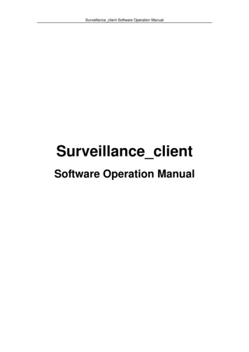
Incu-Mixer Operations ManualChapter 4 Operation guide4.Installing micro test plates — 8 —
Incu-Mixer Operations ManualChapter 5 Failure analysis and troubleshootingChapter 5 Failure analysis and troubleshootingFailure analysis and processing proceduresNo.1PhenomenonNo signal on the display wheninstrument is powered on.Possible CausesProcessing ProcedureNo powerCheck the powerBroken Power LineRepair Power LineBroken switchRepair the switchOthersContactBenchmark Scientific2The actual and displayedtemperaturesarequitedifferent.Broken sensorContactBenchmark Scientific3“OPE.1” in the temperaturedisplay with an audio alarmTemperature sensor inthe lid is disconnectedContactBenchmark Scientific4“OPE.2” in the temperaturedisplay with an audio alarmTemperature sensor inthe heating plate isdisconnectedContactBenchmark Scientific5“SHO.1” in the temperaturedisplay with an audio alarmTemperature sensor inthe lid is shortedContactBenchmark Scientific6“SHO.2” in the temperaturedisplay with an audio alarmTemperature sensor inthe heating plate isshortedContactBenchmark Scientific7“HHH.1” in the temperaturedisplay with an audio alarmOver temperature alarmfor lidContactBenchmark Scientific8“HHH.2” in the temperaturedisplay with an audio alarmOver temperature alarmof heating blackContactBenchmark Scientific9“ERR1” in the speed displaywith an audi alarmRotor lockedContactBenchmark Scientific10“ERR2” in the speed displaywith an audio alarmRotor is running, butdisplay is “0 rpm”ContactBenchmark Scientific11“ERR3” in the speed displaywith an audio alarmActual Speed over max.speedContactBenchmark Scientific12No heating of the heatingblockBroken heater13Press invalidBroken film switch— 9 —ContactBenchmark ScientificContactBenchmark Scientific
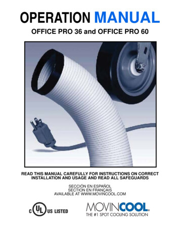
Incu-Mixer Operations ManualAnnexAnnex 1 Wiring Diagram of Incu-Mixer MP(This diagram is just for your reference. Subject to change without notice.)LPE0.5mm2L124VPowerLPENEarth er LidJ1124V J10Main BoardLPENAC inJ60.5mm20.5mm2LidPower BlockJ1Sensor LidJ2Senor BlockJ7motorDisplay interfaceMoterJ9DIDE16wireDisplay Board— 10 —J3SensorLidSensorBlock
Note
product failure, please contact Benchmark Scientific. Read the Manual carefully before operation, The expert of wiring equipment can operate this Instrument. Read the Manual carefully before operation, The expert of wiring equipment can operate this Instrument. Read the Manual carefully before operation, The expert of wiring


![[meat] OP12 Operation - SupplyHouse](/img/53/movincool-op24-operatormanual.jpg)