Transcription
OPERATION MANUALOFFICE PRO 36 and OFFICE PRO 60READ THIS MANUAL CAREFULLY FOR INSTRUCTIONS ON CORRECTINSTALLATION AND USAGE AND READ ALL SAFEGUARDSSECCIÓN EN ESPAÑOLSECTION EN FRANÇAISAVAILABLE AT WWW.MOVINCOOL.COM
2009 DENSO SALES CALIFORNIA, INC.All rights reserved. This book may not be reproduced or copied, inwhole or in part, without the written permission of the publisher. DENSOSALES CALIFORNIA, INC. reserves the right to make changes withoutprior notice. MovinCool is a registered trademark of DENSOCorporation.
OPERATION MANUALOFFICE PRO 36 and OFFICE PRO 60
Table of ContentsFOREWORD. 5Definition of Terms.5GENERAL WARNINGS & CAUTIONS . 6INVENTORY . 7INSTALLATION. 8Choosing an Installation Site .8Moving the Unit .9Plugging in the Unit .10Warning Signal Connection .11Fire Alarm Control Panel Connection .12LCDI Power Cord Instruction .13FEATURES. 14OPERATION. 15Control Panel .15LCD Indicators.16Set Clock .17Operating in COOL Mode .17Operating in FAN ONLY Mode .18Changing from FAN ONLY Mode to COOL Mode.18How to Set a Program .19How to View and Delete Program .20How to Run and Stop Program .20Operating Modes .21Self-Diagnostic Codes .22Empty the Drain Tank (If equipped).23Drain Pump .24HOSE INSTALLATION . 25DAILY INSPECTION & MAINTENANCE . 26Empty the Drain Tank .26Clean the Air Filters .26Filter Removal Method.26Filter Cleaning Method.27In-Season/Off-Season Inspection & Maintenance.27TROUBLESHOOTING . 28TECHNICAL SPECIFICATONS . 294
FOREWORDCongratulations on purchasing the MovinCool portable air conditioner. Thismanual explains how to assemble, install and operate the MovinCool Office Pro36, and Office Pro 60 portable air conditioning units. Please read this operationmanual thoroughly to familiarize yourself with the features of the unit and toensure years of reliable operation.You may also find it useful to keep this operation manual on hand for reference.Components and/or procedures are subject to change without prior notice.Definition of TermsWARNING: Describes precautions that should be observed in order toprevent injury to the user during installation or unit operation.CAUTION: Describes precautions that should be observed in order toprevent damage to the unit or its components, which may occur duringinstallation or unit operation if sufficient care is not taken.Note: Provides additional information that facilitates installation on unit operation.5
GENERAL WARNINGS & CAUTIONS1. All electrical work, if necessary, should only be performed by qualifiedelectrical personnel. Repair to electrical components by non-certifiedtechnicians may result in personal injury and/or damage to the unit. Allelectrical components replaced must be genuine MovinCool parts, purchasedfrom an authorized reseller.2. The proper electrical outlet for MovinCool units must be equipped with a ULapproved ground-fault breaker to prevent electrical shock from the unit.3. The Office Pro 36 is equipped with a six (6) foot (1.8 meter) UL approved LCDIpower cord, and the Office Pro 60 is equipped with a six (6) foot (1.8 meter)power cord. For replacement, fixed location (hard wire) or power cordlengthening (extension cord) cords are required, contact your reseller or aqualified electrician for approved replacement methods.4. Never fold or place heavy objects on the power cord. This could result indamage to the power cord causing electrical shock or fire.5. Do not place water or any other liquid on the unit. This can cause damage tothe unit and increase the risk of electrical shock.6. Do not sit or stand on the unit.6
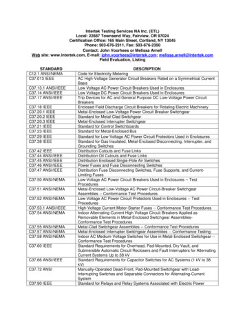
INVENTORYAfter unpacking your MovinCool unit, please check to make sure you have thefollowing items:1. Office Pro 36 or Office Pro 60 MovinCool Unit (1)2. Operation Manual / Product Registration (1)Note: If any of these items were not included in the box or appear damaged,please contact your MovinCool reseller for replacement.OPERATION MANUAL /PRODUCT REGISTRATIONOFFICE PRO 36 MOVINCOOL UNITOPERATION MANUAL /PRODUCT REGISTRATIONOFFICE PRO 60 MOVINCOOL UNIT7
INSTALLATIONChoosing an Installation SiteCAUTION: Following are some precautions to consider before choosingyour installation site. Please review carefully as improper installation mayresult in personal injury or damage to the unit.1. Do not use the unit in areas where leakage of flammable gas may occur.2. Do not use the unit in areas where it is exposed to rain or water.3. Do not use the unit in an atmosphere of excessively corrosive gas or vapor.4. Do not use in areas where the temperature is outside the allowable operatingrange.5. Do not install the unit in sloping areas. The unit may move or topple over evenif the casters are set to the LOCKED position.6. Install the unit in areas that can with-stand the weight of the unit. The OfficePro 36 unit weighs approximately 427 lbs (194kg), and the Office Pro 60 unitweighs approximately 623 lbs (282kg) (when the drain tank is full of water).7. Allow 24 inches (610mm) of unobstructed airflow for both the air inlets andoutlets.8. Do not use the Office Pro 36 unit at condition above 95 F (35 C).9. Do not use the Office Pro 60 unit at condition above 106 F (41 C).8
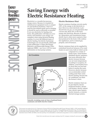
INSTALLATION (cont.)Moving the UnitUnlock all 4 casters and push the MovinCool unit, using the front or rear handles,to a flat, level surface and set the casters back to the LOCKED position.UNLOCKEDLOCKEDUNLOCKEDLOCKED9
INSTALLATION (cont.)Plugging in the Unit1. Check the prong and surface of the power cord plug for dust/dirt. If dust and/or dirt are present, wipe off with a clean, dry cloth.2. Check the power cord, plug and prong for damage or excess play. If anydamage or excess play is found, contact your MovinCool reseller for repair.WARNING:1. If the power cord or plug is damaged, repair should only beperformed by qualified electrical personnel.2. Do not connect/disconnect the power cord or attempt to operatebuttons with wet hands. This could result in electrical shock.CAUTION:1. Office Pro 36 ONLY: The AC outlet (208/230 VAC Single Phase, 60Hz)needs to be rated at 30A or higher. Do not share the outlet with anyother instrument or equipment.2. Office Pro 60 ONLY: The AC outlet (208/230 VAC Single Phase, 60Hz)needs to be rated at 50A or higher. Do not share the outlet with anyother instrument or equipment.Note:1. Make sure the AC outlet is free of dirt, dust, oil, water or any other foreignmatter.2. The Office Pro 36 is equipped with a UL approved LCDI cord and an approvedNEMA plug configuration (6-30).The appropriate outlet must be used for this plug type.3. The Office Pro 60 is equipped with an approved NEMA plug configuration (650).The appropriate outlet must be used for this plug type.10
INSTALLATION (cont.)Warning Signal Connection(Output Signal Terminal L and L-)The controller is equipped with a warning signal output relay type (Form C, normalopen dry contact) which can be used to monitor the failure condition.Relay contactor (not connector) is closed when the following condition hasoccurred:a. Tank fullb. Temperature sensor failsc. High pressure switch errorThe relay output contactor is rated 2A at 30VDC or 2A at 30VAC (resistive load)and it is compatible with various warning devices such as alarm speaker, lightindicators, etc.Connecting Warning Signal From Controller1. Remove service panel from the rear of the unit.2. Push out the back cap from inside. (In case of hand to remove, please pushinner latches of the cap one-by-one.)3. Use recommended warning signal wire size from 16AWG to 26AWG for a solidwire, or 16AWG to 22AWG for a stranded wire with ring terminal for #6 studsize.4. Connect warning device to terminal L and L- according to its polarities.11
INSTALLATION (cont.)Fire Alarm Control Panel Connection(Input Signal Terminal E and E-)The controller is equipped with a normal open input signal, which can beconnected directly from the fire alarm control panel. When receiving the signalfrom the fire alarm control panel, the unit turns off and does not turn back on untilit has been RESET.Connecting Fire Alarm Control Panel to Controller1. Remove service panel from the rear of the unit.2. Squeeze the inner latches and push out the black cap from inside the panel(see drawing of cap and inner latch shapes).3. Use recommended warning signal wire size from 16AWG to 26AWG for a solidwire, or 16AWG to 22AWG for a stranded wire with ring terminal for #6 studsize.4. Connect warning device to terminal E and E- according to its inalsLatch12
INSTALLATION (cont.)LCDI Power Cord Instruction(Office Pro 36 ONLY)WARNINGThe LCDI device is non-serviceable device. Attempting to open the device may expose theuser to hazardous of electric shock, and could void warranties of this product.Manufacturer’s reliability is limited to the replacement of the device.CAUTION1.2.3.4.5.6.7.8.Read the attention printed on the device for proper use and handling of this device.This device is used for monitoring leakage current.Do not immerse in water.This device must only be plugged into appropriate wall outlet. Do not use on extensioncords or adapter. Do not remove ground prong.In the event that this device trips, the cause of malfunction should be corrected first beforefurther use.Using the device beyond recommended voltage poses risk to users.Conductors inside this cord are surrounded by shields, which monitor leakage current.These shields are not grounded, and they are periodically examined the cord for anydamage. Do not use this product in the event the shields become exposed.Do not push TEST and/or RESET buttons in a short period.ProcedureTest device once when AC is installed to assure proper operation.1. Plug into grounded power receptacle.2. If light is not on, press RESET button once. Light should turn on.3. Press TEST button once, light must turn off.4. Press RESET button once again for use. Light should turn on.5. If test fails, do not use. TYPE 1 TYPE 2 TYPE 3 TEST ButtonTEST ButtonRESET ButtonRESET ButtonRESET ButtonTEST Button13POWERTESTRESETLCDI
FEATURESFor all models:1. A digital electronic control panel, which allows the user to control the unit’soperation easily.2. Dual fan speeds (either HIGH or LOW) in both COOL and FAN ONLY modes.3. Digital LCD display with blue backlight that indicates:a. Clock with day and timeb. Room temperature and set point temperature(either Fahrenheit or Celsius)c. Fan speed statusd. Cool mode statuse. Program start time and stop timef. Program run and stopg. Status codesh. Key locked option4. The set point temperature can be adjusted between 65 F and 90 F by the SETTEMP buttons ( / ).5. Fire alarm control panel connection ready for automatic shut off.6. Automatic shut off and warning signal output and alarm for temperature sensorfailure, cooling failure.7. A condensate drain “TANK FULL” indicator (LED) and display (LCD).8. An automatic restart feature when the power is lost and regained.9. A condensate pump with safety switch shut off (optional accessory for OfficePro 36).14
OPERATIONControl PanelBefore operating the unit, it is important to familiarize yourself with the basiccontrols located on the control panel.1. COOL Mode ButtonActivates/deactivates the COOL mode/turns theunit off.2. FAN Mode ButtonActivates/deactivates the high, low, and off fanspeed.3. SET TEMP Button (/) Temperature scale illuminates to indicate thecurrent LED temperatures being displayed areeither in C or F; also displays the clock whenprogramming.4. ENTER ButtonPress to select set up value.5. SET CLOCK ButtonPress to set clock (day and time).6. SET PROG ButtonPress to set or view program.7. RUN/STOP ButtonActivates/deactivates program(s).8. TANK FULL LEDFlashes when the drain tank is full.15
OPERATION (cont.)Control Panel (cont.)LCD Indicators9. MO.SUIlluminates to indicate selected day of the week.10. C or FTemperature displayed in either Fahrenheit orCelsius (see Note).11. AM/PMIlluminates to indicate AM or PM time of day.12. PROGRAMBlinking during program editing mode.13. PROGRAM ONIlluminates to indicate program is running.14. STARTIlluminates to indicate program start time.15. STOPIlluminates to indicate program stop time.16. CLOCKIlluminates to indicate clock status.17. FAN HI/LOIlluminates to indicate selected fan speed.18. COOL ON/OFFIlluminates to indicate cool on or off.19. LOCKEDIlluminates to indicate key lock up.Note: ROOM TEMP display range from 16 F to 109 F (-9 C to 42 C). InFahrenheit only, when display values are greater than 99 F, it displays values of 0F (for 100 F), 1F (for 101 F) and 9F (for 109 F).16
OPERATION (cont.)Set ClockPrior to operating the Office Pro 36 or Office Pro 60 users should set the clock ofthe controller to the correct time as shown in the steps below.1. Press and hold the SET CLOCK buttonfor 3 seconds or until beep.(LCD indicates blinking “CLOCK” andblinking “day of the week”.)2. Press SET TEMP buttons to select dayof the week.3. Press ENTER button to set hour.Step 1 & 64. Press SET TEMP buttons to selectdesired hour.Step 2 to 55. Press ENTER button to set minute.6. Press SET TEMP buttons to selectdesired minute. Press SET CLOCKbutton to exit set clock mode.Note: User should check clock periodically to confirm clock accuracy.Operating in COOL Mode1. The unit can be operated in COOL mode by pressing the COOL ON/OFFbutton (LCD indicates “COOL ON”).Note: In COOL mode the unit can only be turned off by pressing the COOLON/OFF button again, not by pressing the fan buttons.2. Change the fan speed by pressing the FAN HI/LO button.3. Change the temperature set point by pressing the SET TEMP buttons ( / ).Note: When turning the unit on, the set point and fan speed are determined bythe last operating mode. (This function does not apply to PROGRAM mode.)17
OPERATION (cont.)Operating in FAN ONLY Mode1. The unit can also be operated in FAN ONLY mode by pressing FAN HI/LObutton (LCD indicates “FAN HI/LO” and “COOL OFF”).2. The unit can then be turned off by pressing the FAN HI/LO button until fanturns off (FAN ONLY mode speed sequences are HI LO OFF).Changing from FAN ONLY Mode to COOL ModeThe COOL mode can be activated while the unit is operating in FAN ONLY mode.To do this, simply press the COOL ON/OFF button (LCD indicates “COOL ON”).Note: The FAN ONLY mode does not operate after the COOL mode has beenactivated. After the COOL mode has been activated, the unit cannot be turned offby pressing the fan buttons. The COOL ON/OFF button must be pressed.18
OPERATION (cont.)How to Set a ProgramSET START TIME1. Press and hold the SET PROG buttonfor 3 seconds or until beep.2. Press SET TEMP buttons to select dayof the week.3. Press ENTER button.4. Press SET TEMP buttons to selectdesired hour.5. Press ENTER button.6. Press SET TEMP buttons to selectdesired minute.7. Press ENTER button.SET STOP TIME8. Press SET TEMP buttons to select day of the week.9. Press ENTER button.10. Press SET TEMP buttons to select desired hour.11. Press ENTER button.12. Press SET TEMP buttons to select desired minute.13. Press ENTER button.SET FAN SPEED14. Press SET TEMP buttons to select desired fan speed.15. Press ENTER button.SET SET-POINT TEMPERATURE16. Press SET TEMP buttons to select desired temperature.17. Press ENTER button.EXIT PROGRAM EDITING MODE18. Press SET PROG button to exit program editing mode.EDIT MULTIPLE PROGRAMS19. Repeat step 1. to 18. to set up multiple programs.Note: Maximum 7 programming sequences19Step 1 & 18Step 2 to 17
OPERATION (cont.)How to View and Delete Program1. Press and hold the SET PROG button for 3 seconds or until beep.2. To view edited program - While pressing and holding the SET PROG button,press SET TEMP ( / ) to scroll the program sequence.3. To delete a program - Press ENTER and SET PROG buttons oncesimultaneously.4. To delete multiple program - Press and hold ENTER and SET PROG buttonssimultaneously.How to Run and Stop Program1. Press RUN/STOP button to activate preset program (LCD indicates“PROGRAM ON”). During PROGRAM RUN mode, if you push RESET (seepage 22), PROGRAM RUN mode is terminated. To resume PROGRAM RUNmode, you must push RUN/STOP button again.2. Press RUN/STOP button to stop program.Note:1. The unit returns to the previous mode if a program is turned off while it isrunning.2. The LCD continues to indicate “PROGRAM ON” during program activating.3. Program can be set during power on standby, during unit running, or duringprogram running.4. During programming, the unit returns to the previous mode if no activity occurswithin approximately 3 minutes.20
OPERATION (cont.)Operating ModesOffice Pro 36 and Office Pro 60 operate in 2 modes, FAN ONLY and COOL. Whenin FAN ONLY mode, the unit circulates the surrounding air, Office Pro 60 isequipped with an automatic fan speed control when operating in FAN ONLYmode. When in COOL mode, the compressor is operational and cool air iscirculated. Both Office Pro 36 and Office Pro 60 are equipped with automaticcondenser fan speed control depending on room temperature.Office Pro 36 and Office Pro 60 operate in FAN ONLY mode for approximately 120seconds before the compressor engages.(Time delay setting is around 120 seconds.)1. Temperature ControlThe room temperature thermistor allows the unit to switch automatically betweenCOOL and FAN ONLY modes. This is dependent upon inlet air temperature versusset point temperature.2. Fan Mode Control DIP SwitchThe fan mode control DIP switch determines whether the fan continues to operateor stop when the compressor cycles off. (Set point temperature equals inlet air orroom temperature.) The unit has been preset at the factory for continuous fanoperation.3. Temperature Scale Display DIP SwitchThe temperature scale display DIP switch changes the temperature(s) that aredisplayed to either C or F. The unit has been preset from the factory to display thetemperature(s) in F.Note: If you wish to change the fan mode operation (OPERATE to STOP), and/orthe temperature scale display ( F to C), contact your MovinCool reseller.21
OPERATION (cont.)Self-Diagnostic CodesSelf-diagnostic codes are displayed on the control board under the followingconditions:LCD Display CodesConditionWhen the drain tank switch shuts off the unit, LCD displays“TANK FL” and “TANK FULL” LED flashes.Once emptying the drain tank procedure is completed andON/OFF has been pushed, unit returns to normal operation.When the drain pump malfunctions, the compressor shuts off,and the LCD displays “AS”. Once drain pump is fixed and unithas been RESET, the unit returns to normal operation.Contact your MovinCool reseller if problem persists.When high pressure switch is activated, display shows “HP” ifhigh pressure switch is activated 3 times in 24 hours, unitdisplays blinking “HP” and a buzzer turns on.Unit returns to normal operation after problem is fixed andcontroller is RESET (see page 28).Contact your MovinCool reseller if problem persists.To RESET press FAN HI/LO and COOL ON/OFF buttonssimultaneously for 3 seconds, controller returns to normaloperation.When room thermistor becomes open or shorted, displayshows “OPEN RT” or “SHRT RT” and cool mode operation isoff. Display and cool mode operation are returned to normaloperation after room thermistor is fixed. Contact yourMovinCool reseller if problem persists.When freeze thermistor becomes open or shorted, displayshows “OPEN FT” or “SHRT FT” and cool mode operation isoff. Display and cool mode operation are returned to normaloperation after freeze thermistor is fixed. Contact yourMovinCool reseller if problem persists.22
OPERATION (cont.)Empty the Drain Tank (If equipped)During COOL mode, condensate water accumulates in the drain tank. When thedrain tank becomes full, the “TANK FULL” LED flashes and LCD displays “TANKFL”, and the alarm signal output is turned ON and the unit turns off automatically.Note: If you want to empty the drain tank, while the unit is in operation, press theCOOL ON/OFF button to turn the unit off.OFFICE PRO 36 MODELOFFICE PRO 60 MODEL1. Open the front panel of Office Pro 36 or drain tank door of Office Pro 60.2. Pull the drain tank from the unit, display indicates “TANK” and alarm signaloutput stays ON.3. Remove the cap and empty the drain tank.4. Replace the cap and return the drain tank to the unit.5. Close the front panel or drain tank door.6. Press the COOL ON/OFF button to continue running the unit, display andalarm signal return to normal operation.23
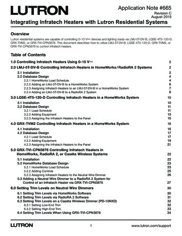
OPERATION (cont.)Drain PumpA drain pump is included for the Office Pro 60 model only, for the Office Pro 36 thedrain pump is an optional accessory item.The drain pump provides a continuous operation and eliminates the need for adrain tank.1. When the water collects to level (A) in thepump reservoir, the drain pump begins tooperate and discharge the water. Duringdrain pump operating period, thecompressor cycles off.2. When the water level drops below level (B),the drain pump stops and compressorrestarts after delay time has expired.Note:1. If for any reason the water levelexceeds that of level (A) in the pumpreservoir, an overflow drain switch stopsthe compressor operation.2. If the fan mode control DIP switch (seepage 21) has been set from the COOLto the STOP position, the Fan also turnsoff while the drain pump is dischargingthe water.24
HOSE INSTALLATIONNote: The Office Pro 60 is equipped with a 20 foot (6m) hose.Connect the 20 foot (6m) hose to the drain stem and feed it through the grommeton the right hand side of the unit.DRAIN STEMDRAIN HOSEDRAIN HOSEDRAIN HOLENote: The pump’s maximum lift is 17 feet (5.2m) at 230VAC (13 feet (4m) at208VAC). Please check the drainage performance after installation. It is importantthat the drainage line from the pump is free of kinks and is not pinched. Powerfluctuation or low voltage could result in incorrect drainage.To insure proper drainage, locate the highest vertical position, no more than 17feet (5.2m) at 230VAC (13 feet (4m) at 208VAC), and run the drain hose on adownward slope at a minimum rate of 1/4 inch (6.25mm) per foot.17’ (5.2m) MAX1/4” (6.25 mm)TAPER PER FOOTCONDENSATEPUMPGROMMET25
DAILY INSPECTION & MAINTENANCEEmpty the Drain TankTo empty the drain tank, refer to instructions on page 23.Clean the Air FiltersClean the air filters once a week. If the unit is used in a dusty environment, morefrequent cleaning may be required. A dirty air filter can reduce air output resultingin a decrease of the cooling capacity.Filter Removal Method1. Turn the unit off, by pressing the COOL ON/OFF button. If a program isrunning, you must first press the PROGRAM RUN button.2. Remove the two air filters.Note: To remove the filters from the Office Pro 36 and Office Pro 60, open thefront panel and side panel filter doors. On the side panel door, carefullyremove the filter element from wire frame attachment points. On the front,unclip the wire frame and remove filter.FRONT PANEL FILTER DOORSIDE PANEL FILTER DOORCLIPFILTERFILTERWIRE FRAMECLIPWIRE FRAMECLIPFILTERFILTERWIRE FRAMECLIPWIRE FRAME26
DAILY INSPECTION & MAINTENANCE (cont.)Filter Cleaning Method1. Remove dust from the element with a vacuumcleaner, or rinse in cold or lukewarm water. If theelement is extremely dirty, wash with a neutraldetergent.FILTER2. After the element has been cleaned, rinse withclean running water, allow to dry, then reinstall.In-Season/Off-Season Inspection& MaintenanceIn-Season1. Check the prongs and surface of the power cord plug for dust and/or dirt. Ifdust and/or dirt are present, wipe off with a clean dry cloth.2. Check the power cord, plug and prongs for damage or excess play. If anydamage or excess play is found, contact your MovinCool reseller for repair.3. Check the air filters and drain tank.4. Clean the outside of the unit(s) with a damp cloth or mild nonabrasive cleaner.Off-Season1. Operate the unit in FAN ONLY mode for 8 hours.Note: Operation is necessary to dry out the inside of the unit.2. Disconnect the power cord from the AC outlet.3. Check the prongs and surface of the power cord plug for dust and/or dirt. Ifdust and/or dirt are present, wipe off with a clean dry cloth.4. Check the power cord, plug and prongs for damage or excess play. If anydamage or excess play is found, contact your MovinCool reseller for repair.5. Clean the air filters.6. Empty all water from the drain tank.27
TROUBLESHOOTINGCheck the following items before calling a qualified technician.SYMPTOMUnit does not operate.Insufficient cooling.POSSIBLE CAUSEREMEDY1. Ground fault breaker trip orLCDI power cord trip.Reset breaker or reset powercord.2. Drain tank is full.(“TANK FULL” LED flashes.)Empty the drain tank.3. High pressure switchactivated 10 times in 24hours.1. Clean air filter.2. Check inlet and outlet air, andmake sure that there werenot any object that mayprevent air flow into or outfrom the unit.3. Check environmentalcondition whether it is withinoperation range or not.4. Reset controller1. Dirty/Blocked air filters.Clean air filter.2. Air inlet/outlet blocked.Clean air inlet/outlet.3. Improper temperature setting.Adjust temperature setting.If symptoms persist after the above actions have been taken, turn the unit off,disconnect the power cord plug and contact your MovinCool reseller.28
TECHNICAL SPECIFICATONSITEMS/FEATURESRating ConditionsDry bulbWet bulbHumiditySpecificationsPower frequencyLine voltagePower consumptionCurrent consumptionPower factorStarting currentPower wiringCooling UnitCooling capabilityCooling systemBlowerType of fanAir volume:Evaporator (high speed)Condenser (high speed)Motor output: HighLowCompressorTypeOutputRefrigerant typeRefrigerant capacitySafety DevicesCompressor overload protectorFan motor protectorAnti-freezing thermistorFull drain tank switchAutomatic restart (power interruption)Compressor time delay programHigh pressure interruptionSignal input/outputDimensions & WeightW D H (in)W D H (mm)Weight (lbs/kg)Operating ConditionsInlet air (relative humidity)Office Pro 36Office Pro 6095 F(35 C)83 F(28.2 C)(60%)95 F(35 C)83 F(28.2 C)(60%)60HzSingle Phase re)AWG60HzSingle Phase WG8,820/9,072kcal/hr35,000/36,000Btu/hrDirect rect ExpansionCentrifugal 21/0.13kw0.33/0.12kwCentrifugal .60/0.33kw1.20/0.92kwHermetic Scroll2.3kwR-410A2.38lbs(1.08kg)Hermetic udeIncludeIncludeIncludeIncludeIncludeInclude30” 44” 52”762 1118 1321427/19430” 52” 64”762 1321 1626623/28395 F(35 C) 60%65 F(18.3 C) 50%106 F(41 C) 50%65 F(18.3 C) ol DeviceTemperature controlProgrammable timerTwo speed fan29
LIMITED WARRANTYDENSO SALES CALIFORNIA, INC. (“DENSO”) warrants its MOVINCOOL Products only to theextent stated in its official written warranties. Unless otherwise specifically provided in writing byDENSO, DENSO warr
1. Office Pro 36 or Office Pro 60 MovinCool Unit (1) 2. Operation Manual / Product Registration (1) Note: If any of these items were not included in the box or appear damaged, please contact your MovinCool reseller for replacement. OPERATION MANUAL / PRODUCT REGISTRATION OPERATION MANUAL / PRODUCT REGISTRATION OFFICE PRO 36 MOVINCOOL UNIT