Transcription
Chapter 11:Fundamentals of ��รย ์ เรือโท ดร. สมญาภูนะยาReference : DeGarmo’s Materials and Processes in Manufacturing
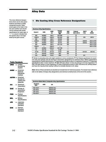
11.1 Introduction Products go through a series of processes beforethey are produced DesignMaterial selectionProcess selectionManufactureInspection and evaluationFeedbackMaterials processing is the science and technologythat converts a material into a product of a desiredshape in the desired quantitiy
Shape-Producing Processes Four basic categories Casting processes (sand casting)Material removal processes (Machining)Deformation processes (forging, extrusion, rolling)Consolidation processes (Welding, Mechanicaljoint)Decisions should be made after allalternatives and limitations are investigated
Shape-Producing ProcessesFigure 11-1 The four materials processingfamilies, with subgroups and typical processes.
11.2 Introduction to Casting Casting process Material is meltedHeated to proper temperatureTreated to modify its chemical makeupMolten material is poured into a moldSolidifiesCasting can produce a large variety of parts
Advantages of Casting Complex shapesParts can have hollow sections or cavitiesVery large partsIntricate shaping of metals that are difficult tomachineDifferent mold materials can be used Sand, metal, or ceramicsDifferent pouring methods
Basic Requirements of Casting Processes Six basic steps of casting 1. Mold cavity is produced having the desiredshape and size of the part 2. Melting process Takes shrinkage into accountSingle-use or permanent moldProvides molten material at the proper temperature3. Pouring technique Molten metal is poured into the mold at a proper rate toensure that erosion and or defects are minimized
Six Basic Steps of Casting 4. Solidification process Controlled solidification allows the product to have desiredpropertiesMold should be designed so that shrinkage is controlled5. Mold removal The casting is removed from the mold Single-use molds are broken away from the castingPermanent molds must be designed so that removal does notdamage the part6. Cleaning, finishing, and inspection operations Excess material along parting lines may have to bemachined
11.3 Casting Terminology Pattern- approximate duplicate of the part to be castMolding material- material that is packed around thepattern to provide the mold cavityFlask- rigid frame that holds the molding aggregateCope- top half of the patternDrag- bottom half of the patternCore- sand or metal shape that is inserted into themold to create internal features
Casting Terminology Mold cavity- combination of the mold material andcoresRiser-additional void in the mold that providesadditional metal to compensate for shrinkageGating system- network of channels that delivers themolten metal to the moldPouring cup- portion of the gating system thatcontrols the delivery of the metalSprue- vertical portion of the gating systemRunners- horizontal channelsGates- controlled entrances
Casting Terminology Parting line- separatesthe cope and dragDraft- angle or taper ona pattern that allows foreasy removal of thecasting from the moldCasting- describes boththe process and theproduct when moltenmetal is poured andFigure 11-2 Cross section of a typical two-part sandmold, indicating various mold components andsolidifiedterminology.
Cross Section of a MoldFigure 11-2
11.4 The Solidification Process Molten material is allowed to solidify into thefinal shapeCasting defects occur during solidification Gas porosity (solved by adding the vent)Shrinkage (solved by using the riser to add themolten metal)Two stages of solidification NucleationGrowth
Nucleation Stable particles form from the liquid metalOccurs when there is a net release of energy fromthe liquidUndercooling is the difference between the meltingpoint and the temperature at which nucleationoccursEach nucleation event produces a grain Nucleation is promoted (more grains) for enhancedmaterial propertiesInoculation or grain refinement is the process of introducingsolid particles to promote nucleation
Grain Growth Occurs as the heat of fusion is extracted fromthe liquidDirection, rate, and type of growth can becontrolled Controlled by the way in which heat is removedRates of nucleation and growth control the sizeand shape of the crystalsFaster cooling rates generally produce finer grainsizes
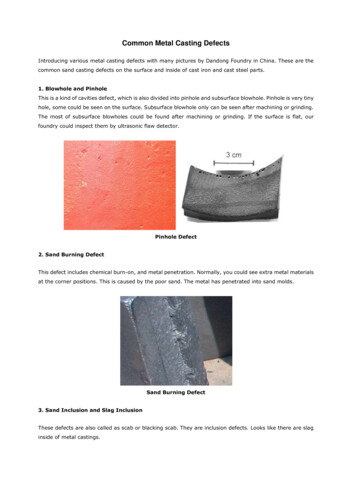
Cooling Curves Useful for studying thesolidification processCooling rate is the slopof the cooling curveSolidification can occurover a range oftemperatures in alloysBeginning and end ofsolidification areindicated by changes inslopeFigure 11-3 Cooling curve for a pure metal oreutectic-composition alloy (metals with a distinctfreezing point), indicating major features relatedto solidification.
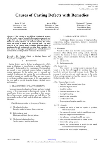
Cooling CurvesFigure 11-4 Phase diagram and companion cooling curve for an alloy with a freezing range. Theslope changes indicate the onset and termination of solidification.
Prediction of Solidification Time:Chvorinov’s Rule Ability to remove heat from a casting is related to thesurface area through which the heat is removed andthe environment that it is rejecting heat toChvorinov’s Rule: ts B(V/A)n where n 1.5 to 2.0ts is the time from pouring to solidificationB is the mold constantV is the volume of the castingA is the surface area through which heat is rejected
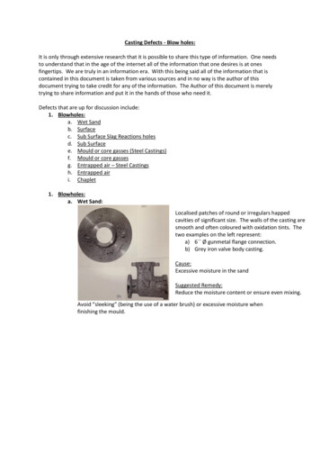
Cast Structure Three distinct regions or zones Chill zone Columnar zone Rapid nucleation that occurs when the molten metal comesinto contact with the cold walls of the moldForms a narrow band of randomly oriented crystals on thesurface of a castingRapid growth perpendicular to the casting surfaceLong and thinHighly directionalEquiaxed zone Crystals in the interior of the castingSpherical, randomly oriented crystals
Cast StructureFigure 11-5 Internal structure of a castmetal bar showing the chill zone at theperiphery, columnar grains growing towardthe center, and a central shrinkage cavity.
Molten Metal Problems Chemical reactions can occur betweenmolten metal and its surroundingsReactions can lead to defects in the finalcastings Metal oxides may form when molten metal reactswith oxygenDross or slag is the material that can be carriedwith the molten metal during pouring and filling ofthe mold Affects the surface finish, machinability, and mechanicalproperties
Molten Metal Problems Gas porosity Gas that is not rejected from the liquid metal may betrapped upon solidificationSeveral techniques to prevent gas porosity Prevent the gas from initially dissolving in the liquid Melting can be done in a vacuumMelting can be done in environments with low-solubility gasesMinimize turbulenceVacuum degassing removes the gas from the liquid before it ispoured into the castingsGas flushing- passing inert gases or reactive gases throughthe liquid metal
Fluidity and Pouring Temperature Metal should flow into all regions of the mold cavityand then solidifyFluidity is the ability of a metal to flow and fill a mold Affects the minimum section thickness, maximum length ofa thin section, fineness of detail, ability to fill moldextremitiesDependent on the composition, freezing temperature,freezing range, and surface tensionMost important controlling factor is pouringtemperature
The Role of the Gating System Gating system delivers the molten metal tothe mold cavityControls the speed of liquid metal flow andthe cooling that occurs during flowRapid rates of filling can produce erosion ofthe mold cavity Can result in the entrapment of mold material inthe final castingCross sectional areas of the channels regulateflows
Gating Systems Proper design minimizes turbulenceTurbulence promotes absorption of gases,oxidation, and mold erosionChoke- smallest cross-sectional area in thegating systemRunner extensions and wells- used to catchand trap the first metal to enter the mold andprevent it from entering the mold cavityFilters- used to trap foreign material
Gating SystemFigure 11-9 Typical gating system for a horizontal parting plane mold, showing key componentsinvolved in controlling the flow of metal into the mold cavity.
FiltersFigure 11-10 Various types of ceramic filters that maybe inserted into the gating systems of metal castings.
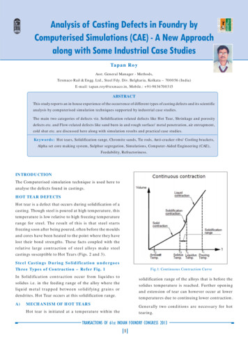
Solidification Shrinkage Most metals undergonoticeable volumetriccontraction when cooledThree principle stages ofshrinkage: Shrinkage of liquid as itcools from the solidificationtemperatureSolidification shrinkage asthe liquid turns into solidSolid metal contraction asthe solidified metal cools toroom temperatureFigure 11-11 Dimensional changesexperienced by a metal column as the materialcools from a superheated liquid to a roomtemperature solid. Note the significantshrinkage that occurs upon solidification.
Solidification Shrinkage Amount of liquid metal contraction depends on The coefficient of thermal contractionThe amount of superheatAs the liquid metal solidifies, the atomic structurenormally becomes more efficient and significantamounts of shrinkage can occurCavities and voids can be prevented by designingthe casting to have directional solidificationHot tears can occur when there is significant tensilestress on the surface of the casting material
Risers and Riser Design Risers are reservoirs of liquid metal that feed extrametal to the mold to compensate for shrinkageRisers are designed to conserve metalLocated so that directional solidification occurs fromthe extremities of the mold toward the riserShould feed directly to the thickest regions of thecastingBlind riser- contained entirely within the mold cavityLive riser- receive the last hot metal that enters themold
Risers and Riser DesignFigure 11-13 Schematic of a sand casting mold, showing a) an open-type top riserand b) a blind-type side riser. The side riser is a live riser, receiving the last hotmetal to enter the mold. The top riser is a dead riser, receiving metal that has flowedthrough the mold cavity. Riser must be separated from the casting uponcompletion so the connection area must be as smallas possible
Riser Aids Riser’s performance may be enhanced by speedingthe solidification of the casting (chills) or slowingdown the solidification (sleeves or toppings)External chills Masses of high-heat capacity material placed in the moldAbsorb heat and accelerate cooling in specific regionsInternal chills Pieces of metal that are placed in the mold cavity andpromote rapid solidificationUltimately become part of the cast part
Go to ch 12
11.5 Patterns Two basic categories for casting processes Expendable mold processesPermanent mold processesPatterns are made from wood, metal, foam,or plasticDimensional modification are incorporatedinto the design (allowances) Shrinkage allowance is the most importantPattern must be slightly larger than the desiredpart
Dimensional Allowances Typical allowances Cast iron 1.3%Brass1.5%Shrinkage allowances are incorporated into thepattern using shrink rulesThermal contraction might not be the only factor fordetermining pattern sizeSurface finishing operations (machining, etc.) shouldbe taken into consideration
Pattern Removal Parting lines are the preferred methodDamage can be done to the casting atcorners or parting surfaces if tapers or draftangles are not used in the pattern Factors that influence the needed draft Size and shape of patternDepth of mold cavityMethod used to withdraw patternPattern materialMold materialMolding procedure
Design ConsiderationsFigure 11-14 Two-part mold showing the partingline and the incorporation of a draft allowance onvertical surfaces.Figure 11-15 Various allowancesincorporated into a casting pattern.
11.6 Design Considerations in Castings Location and orientation of the parting line isimportant to castingsParting line can affect: Number of coresMethod of supporting coresUse of effective and economical gatingWeight of the final castingFinal dimensional accuracyEase of molding
Design ConsiderationsFigure 11-17 (Right) Elimination of a drysand core by a change in part design.Figure 11-16 (Left) Elimination of a core bychanging the location or orientation of theparting plane.
Design Considerations It is often desirable to minimize the use of coresControlling the solidification process is important toproducing quality castingsThicker or heavier sections will cool more slowly, sochills should be used If section thicknesses must change, gradual is betterIf they are not gradual, stress concentration points can becreated Fillets or radii can be used to minimize stress concentrationpointsRisers can also be used
Parting Line and DraftsFigure 11-18 (Top left) Design where the location of the parting plane is specified by thedraft. (Top right) Part with draft unspecified. (Bottom) Various options to produce the topright part, including a no-draft design.
Section ThicknessesFigure 11-19 (Above) Typical guidelines for section change transitions in castings.Figure 11-20 a) The “hot spot” at section r2 is cause by intersecting sections. B) An interior fillet andexterior radius lead to more uniform thickness and more uniform cooling.
Design Modifications Hot spots are areas of the material that cool moreslowly than other locations Function of part geometryLocalized shrinkage may occurFigure 11-21 Hot spots often result from intersecting sections of various thickness.
Design Modifications Parts that have ribs may experience crackingdue to contraction An excess of material may appear around theparting line Ribs may be staggered to prevent crackingThe parting line may be moved to improveappearanceThin-walled castings should be designed withextra caution to prevent cracking
Design ModificationsFigure 11-23 Using staggered ribs to prevent cracking during
ensure that erosion and or defects are minimized . Six Basic Steps of Casting 4. Solidification process Controlled solidification allows the product to have desired properties Mold should be designed so that shrinkage is controlled 5. Mold removal The casting is removed from the mold Single-use molds are broken away from the casting Permanent molds must be designed so that removal does not .File Size: 1022KBPage Count: 48