Transcription
International Journal of Engineering Research & Technology (IJERT)ISSN: 2278-0181Vol. 2 Issue 8, August - 2013Identification of Casting Defects by Computer Simulation –A ReviewVipul M Vasava1, Prof D.R.Joshi 21. P.G.Student (CAD/CAM) 2.Assistant ProfessorSardar Vallabhbhai Patel Institute of Technology,Vasad.Gujarat-IndiaAbstract1. Alloys of Aluminum Includes Alnico,Duralumin, Zamak and Silumin.2. Alloys of Bismuth Includes Woods metal,Fields Metal and Rose metal.3. Alloys of Cobalt The most common alloys areStellite, Vitallium, Ultimet and Talonite.4. Alloys of Copper Includes Arsenical copper,brass, bronze, cunife, nickel silver, Nordicgold and manganin5. Alloys of Gold the main alloys containinggold are Tumbaga, Electrum, White Gold andRose Gold6. Alloys of Iron Includes Pig Iron, Cast Iron,Wrought Iron and Anthracite Iron.7. Other alloys include ferrous alloys like steeland lead alloys like solder.8. Steel casting is better than all other alloycastings as they offer superior tensile andshear strength. This allows steel castings to beused in hydroelectric turbines, gears, valvebodies, mining machinery and railroad truckframes. The main benefits of alloy steelcastings are:IJERTMost common defect in steel castings is porosity,hotspot, blowholes.As a consequence the porosityformation is very closely studied phenomenon. Theinvestigation described in this paper will examined theporosity formation in the casting component ofHousing. In the current environment many casters stilluse the trial and error approach for processdevelopment. The capability to produce sound castingcomponent of high quality of the same time reducingproduct costs & development times is the most highlychallenge for the foundry today.elements, the engineering properties like shear strengthand tensile strength can be completely different. Thereare many different types of alloys made in castingfoundries and the most common alloy castings in Indiaare as follows.Computer aided modeling plays an important role forthe foundry industry for the past several years. Not onlywith the new design components but also in theredesign of existing products.Simulation gives theobserved porosity and it will give the possibility toreduce porosity by changing appropriate gatingsystem, riser design & modification.1. IntroductionCasting is a manufacturing process by which a liquidmaterial is usually poured into a mold, which contains ahollow cavity of the desired shape, and then allowed tosolidify. The solidified part is also known as a casting,which is ejected or broken out of the mold to completethe process. Casting is a metal part formed by pouringmolten metal into a sand mold or metal die. The moldor die is comprised of two halves that, when matedtogether, form a cavity into which the molten metal ispoured. The mold or die from the external surface ofthe casting. If an internal cavity is required in thecasting, a core is placed inside the mold cavity. Incasting process, after the metal solidifies, the mold isbroken, the cores removed and the part is readied forfinishing operations. The sand is then remolded andused again. When a metal die is used, the two halves ofthe die are separated and the solidified casting isremoved. The die is then reused.As a combination of two of more elements is referredto as an alloy provided the final combination hasmetallic properties. Though the physical properties ofan alloy do not differ much from its constituentIJERTV2IS80436This casting has a very high resistance to corrosion dueto the presence of chromium, which prevent iron fromcombining with air and water and rusting. It also hasthe capability to reflect light as a result if which itappears bright. Steel casting is a specialized formof casting involving various types of steel. Steelcastings are used when cast irons cannot deliver enoughstrength or shock resistance. Examples of items that aresteel castings include: hydroelectric turbine wheels,forging presses, gears, railroad, truck, valve bodies,pump casings, mining machinery, marine equipment,turbocharger turbines and cylinder blocks.www.ijert.org2550
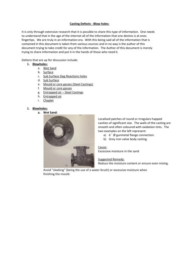
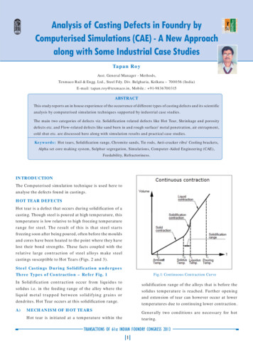
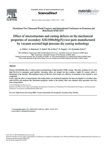
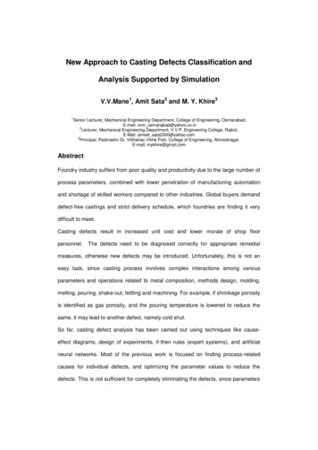
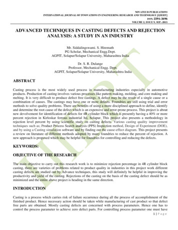
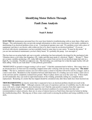
International Journal of Engineering Research & Technology (IJERT)ISSN: 2278-0181Vol. 2 Issue 8, August - 2013solid metals, when a metal begins to solidify, thedissolved gases are expelled from the solution. It willcause microporisty or accumulate in regions of existingporosity.2. Casting ProcessCasting is a manufacturing process by which a liquidmaterial is usually poured into a mold, which contains ahollow cavity of the desired shape, and then allowed tosolidify. The solidified part is also known as a casting,which is ejected or broken out of the mold to completethe process.Casting is a metal part formed by pouring molten metalinto a sand mold or metal die. The mold or die iscomprised of two halves that, when mated together,form a cavity into which the molten metal is poured.The mold or die from the external surface of thecasting. If an internal cavity is required in the casting, acore is placed inside the mold cavity.Incomplete filling [2] is primarily caused by poorfluidity of molten metal, and manifests in the form of acold shut or misrun. A cold shut occurs when twostreams of molten metal coming from oppositedirections meet, but don’t fuse completely. A misrunoccurs when the molten metal does not completely filla section of the mould cavity. The presence of surfaceoxides and impurities on the advancing front of liquidmetal aggravates such defects.IJERTIn casting process, after the metal solidifies, the mold isbroken, the cores removed and the part is readied forfinishing operations. The sand is then remolded andused again. When a metal die is used, the two halves ofthe die are separated and the solidified casting isremoved. The die is then reused. As a combination oftwo of more elements is referred to as an alloy providedthe final combination has metallic properties. Thoughthe physical properties of an alloy do not differ muchfrom its constituent elements, the engineeringproperties like shear strength and tensile strength canbe completely different.Figure 1 Example of porosity3.Casting PorosityFigure 2 Cold-shut defectUnderstanding the various porosity-type defects alsohelps in casting design. While some defects can befixed by the manufacturing process, others can be fixedthrough design changes or a combination of both. Byknowing the casting factors that are likely to contributeto the different defects, you can work with the castingsupplier to avoid potential problems, relocate porosityprone areas to nonstructural sections of the part andestablish mutually acceptable levels of porosity present.Porosity may be the most persistent phenomena incasting, and it is hard to be eliminated completely.Porosity is harmful to the ductility of the casting and itssurface finish. Porosity in castings is due to bubblesbeing trapped during solidification. It may be caused byshrinkage, or gases, or both. There are many factorscontribute to the development of porosity such as theentrapped air during filling, blowholes from unventedcores, dissolved gases from melting, etc. Because liquidmetals have much greater solubility for gases than doIJERTV2IS80436Figure 3 Misrun defectSand holes can arise as result of defective pattern madeand set of gate patterns, figure 4www.ijert.org2551
International Journal of Engineering Research & Technology (IJERT)ISSN: 2278-0181Vol. 2 Issue 8, August - 2013The sand buckle is a build up which arise on the castingsurface as a result of liquid metal penetration to thesurface of sand mould. The small sand strength, hightemperature liquid metal and long time of pouring arethe factors conductive to the sand buckle formation.Moreover, long time of pouring causes that superheatedliquid metal strongly heats the top surface of cavityniche. The shrinkage is defined as shallow andextensive hollow with smooth surface and oval outline,figure 7Figure 4. Sand holes of castingIJERTEssential influence on the arisen of sand holes have aquality of molding sand. In order to decrease of sandholes quantity in castings it is necessary to apply ofmoulding sand with green strength. The local cluster ofsmall voids is defined as porosity, fig. 4. This defectarises frequently as a result of gas separate from asolidification metal.Figure 5 Porosity of castingThe porosity can arise also as a result of gas separatefrom a moulding sand. The mechanism of porosityformation is analogous to the blistering, because thecauses of formation these defects are identical. Themost frequently cause of blowholes formation is gasseparating from a moulding sand, rarely gas separatingfrom solidify metal, fig. 6Figure 7 Shrinkage porosity of castingThe shrinkage can arise only in place, which is not or iswrongly feeding by liquid metal. The wrongly feedingthrough riser can often cause formation of shrinkage incastings. The reason of shrinkages can be also wrongproject of gating system or hot moulding sandThemould shift is defined as part casting displacement withrespect to oneself in parting plane of sand mould orcore. Mould shift can be also caused by theconstructional defects or wrong assembly of sandmould to pouring or attrition of moulding box pins.Thecasting quality is heavily dependent on the success ofgating/riser system design.3.Casting simulationToday, most of the casting simulation packages in themarket can handle solidification and fluid flow in thecasting with satisfactory accuracy. Now, the foundryindustry wants to focus on more advanced predictionssuch as stress and deformation, microstructuredetermination, as cast mechanical properties, microporosity indication and core blowing defects.Figure 6 Blowhole of castingIJERTV2IS80436Even though computer aided process simulation hasbeen available for the past fifteen years, manyinvestment casters still use the conventional trial anderror approach for process development. In manyfoundries, new cast components are often put togetherwww.ijert.org2552
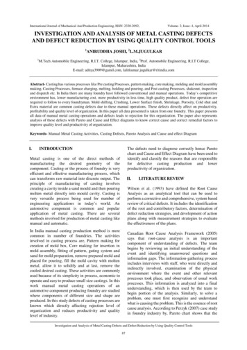
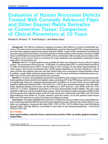
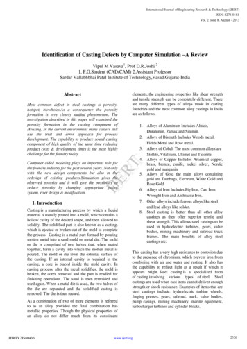
International Journal of Engineering Research & Technology (IJERT)ISSN: 2278-0181Vol. 2 Issue 8, August - 2013In this paper case studies from the industry is analyzedfor the casting process. In some cases, the originalcasting design produced poor quality castings, othershad low yield.Part: 1 Slide gate valve housingIn this case company has a problem in this castingcomponent. This casting had a high rejection due to itsshrinkage defect and sand fall. Rework cost of thisproduct is very high Instead of redesigning the mouldseveral times in trial and-error fashion, the gating andrisering was redesigned with the assistance of computermodeling.IJERTin different departments working independently of eachother. When a new customer's need is identified, thedesign group generates the part drawings. Thenengineering department then identifies the mechanicalstability and establishes guidelines for finalizing thedesign of the component. Finally, the foundry bringsthe component into production, conforming to thestringent specifications provided by the designers.Inevitably, the foundry man is always undertremendous to produce excellent castings within a tightschedule and budget. Unfortunately the traditionalapproach rarely allows the foundry man to participatein the design and engineering phases prior to theproduction stage. In recent years, thanks to advancedcomputer aided technologies and casting processmodeling, the traditional approach is becoming a thingof the past. Process Simulation provides valuableinformation that facilitates participation by the foundryengineer early in the product development stage. Thisreduces the time between the concept stage andproduction stage in the life of a new component.Figure 9 Housing defectFigure 10 CAD model of housingFigure 8 Trial and error developments versus ComputerAssisted DevelopmentIJERTV2IS80436The 3D models of the casting created in ProE areshown in figure 10. The models are incorporated withgating systems as practiced in the foundry. Thepressurized gating system is used so as to fill the cavityfaster and get the maximum yield. It is used to avoidaspiration because straight sprue is provided and it alsoallows all the gates to flow full in multi gated system.The 3D model is converted to stl format.www.ijert.org2553
International Journal of Engineering Research & Technology (IJERT)ISSN: 2278-0181Vol. 2 Issue 8, August - 2013Figure 11 modeling steps with gating systemAs shown in the figure 11 component of housing withmodeling will be shown in figure. Then after based onthat suggestion for the analysis will be carried out onPro-CAST software. Input data for housing andmaterial composition is shown in as underInput data for housingPouring temperature1620 C2Composition of castingA 351 CF8 sand casting3Shrinkage5.10%4Casting volume8843390 mm35Surface area of castings491507 mm26Mold box size735 x 635 x 460 mm7Weight of casting96 Kg8Core materialNo-bake resin9Sand typeNo-bake resin10Inspection test typeVisual and Radiography11Pouring time21 secs12Ingate size100 x 8 x 60 mm13Feed aidsExothermic sleeves,chills14Density7.86 gm/ccMaterial composition of 030.045All this above information then added to the Pro-CASTsoftware for find out the defects and give propersimulation for the above case study .which will be veryhelpful to the industry for better and accurateproduction.CONCLUSION:Producing casting without defect is very difficult task,it require repetatitive effort. In this regard we haveremoved defects by using pro-e software. With the headof exiting set of knowledge, from company peopleswith minimum efforts. It has been observed thatcompany people are not much aware of pro-e software;there is need of interaction between industry andeducation.IJERT1MaterialgradeAdvanced casting simulation tools like Procast allowthe foundry engineer to quickly bridge the gap betweendesign and manufactur
to the different defects, you can work with the casting supplier to avoid potential problems, relocate porosity-prone areas to nonstructural sections of the part and establish mutually acceptable levels of porosity present. Porosity may be the most persistent phenomena in casting, and it is hard to be eliminated completely. Porosity is harmful to the ductility of the casting and its surface .Cited by: 5Publish Year: 2013Author: Vipul M Vasava, D.R.Joshi