Transcription
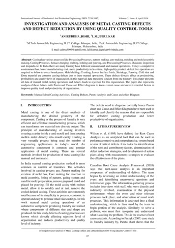
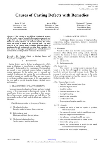
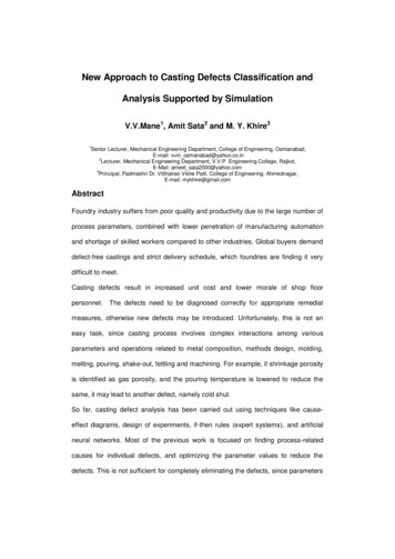
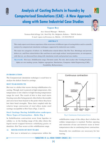
Analysis of Casting Defects in Foundry byComputerised Simulations (CAE) - A New Approachalong with Some Industrial Case StudiesTapan RoyAsst. General Manager - Methods,Texmaco Rail & Engg. Ltd., Steel Fdy. Div. Belgharia, Kolkata – 700056 (India)E-mail: tapan.roy@texmaco.in, Mobile.: 91-9836700315ABSTRACTThis study reports an in house experience of the occurrence of different types of casting defects and its scientificanalysis by computerised simulation techniques supported by industrial case studies.The main two categories of defects viz. Solidification related defects like Hot Tear, Shrinkage and porositydefects etc. and Flow-related defects like sand burn in and rough surface/ metal penetration, air entrapment,cold shut etc. are discussed here along with simulation results and practical case studies.Keywords: Hot tears, Solidification range, Chromite sands, Tie rods, Anti-cracker ribs/ Cooling brackets,Alpha set core making system, Sulphur segregation, Simulations, Computer-Aided Engineering (CAE),Feedability, Refractoriness.INTRODUCTIONThe Computerised simulation technique is used here toanalyse the defects found in castings.HOT TEAR DEFECTSHot tear is a defect that occurs during solidification of acasting. Though steel is poured at high temperature, thistemperature is low relative to high freezing temperaturerange for steel. The result of this is that steel startsfreezing soon after being poured, often before the mouldsand cores have been heated to the point where they havelost their bond strengths. These facts coupled with therelative large contraction of steel alloys make steelcastings susceptible to Hot Tears (Figs. 2 and 3).Steel Castings During Solidification undergoesThree Types of Contraction – Refer Fig. 1Fig.1: Continuous Contraction CurveIn Solidification contraction occur from liquidus tosolidus i.e. in the feeding range of the alloy where theliquid metal trapped between solidifying grains ordendrites. Hot Tear occurs at this solidification range.A)solidification range of the alloys that is before thesolidus temperature is reached. Further openingand extension of tear can however occur at lowertemperatures due to continuing lower contraction.MECHANISM OF HOT TEARSGenerally two conditions are necessary for hottearing.Hot tear is initiated at a temperature within theTRANSACTIONS OF 61st INDIAN FOUNDRY CONGRESS 2013 1
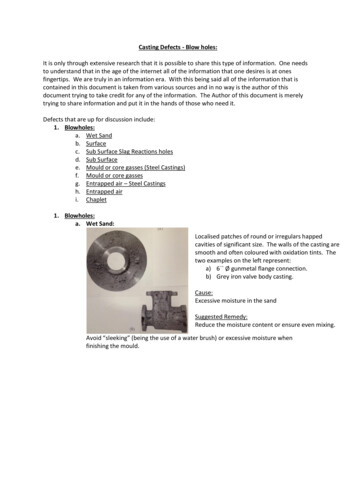
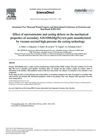
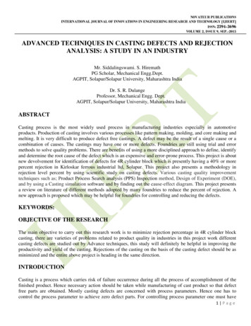
a)There must be resistance to contractions.tearing than sodium silicate bonded sandb)There must be variable temperature gradientswithin the casting section.system.Whenever possible mould and core sectionshould be hollowed out or notch should beprovided at the corners of the hollow block asper Fig.5 for better collapsibility or acollapsible insert such as polystyrene(thermocol) incorporated into the section asclose as possible to the casting surface.Alternately Paper tubes may be inserted at thecorners for better collapsibility Fig.6. Binderlevel and rammed density should be kept to aminimum level.b)Steel Quality- Sulphur and Phosphorouslevel should be kept below 0.02% and theFig.2: Hot tear defects.Mn:S ratio at least 25:1. Deoxidation at a levelavoid deleterious Type II grain boundaryinclusions.c)Hydrogen in Steel – The solubility ofHydrogen in molten steel is 27 ppm. While insolid condition hydrogen has very poorsolubility. The dissolved hydrogen in moltensteel during solidification comes out andcauses hydrogen embrittlement. The stressdeveloped during solidification causes hottear and has led to a numbers of catastrophicfailure e.g. in Bogie items of Indian Railways.Fig.3: Hot tear defects at junctions.By understanding the sources of hydrogen inB)PREVENTION OF HOT TEARgreater detail it has been possible inThere is usually no easy or single cure for consistentoptimising steelmaking processes, minimisingelimination of hot tears, because many factors canhydrogen pickup, and more importantly,contribute for the formation of hot tears.minimising Hot Tear defects.The most common precautionary measuresare as follows :a)d)Pouring Temp.- Pour at a minimumMoulding Materials - Strong, hard mouldstemperature consistent with avoiding coldand cores that collapse slowly under heat ismetal defects and maintain high fill rate.more likely to cause hot tears than weak,e)Feeding Practice – Adequate feeding ofeasily collapsible moulds and cores. Resinisolated hot spots can prevent the formationbonded sand mixes (especially alpha set –of hot tears. Excessive large feeders which mayester cured system) offer lower resistance tohinder contraction should be avoided.TRANSACTIONS OF 61st INDIAN FOUNDRY CONGRESS 2013 2
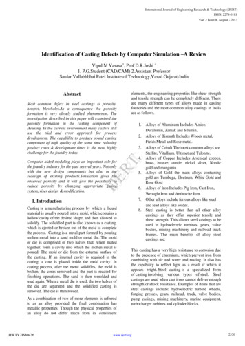
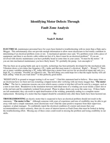
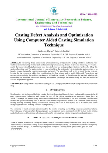
f)Gating Practice- Multiple gates should beused to even out temperature gradients andlocally overheated mould parts should also beavoided.Care should be taken to ensure that the designof runners and gates is not “tying” the castingand restricting normal contraction. Overfilling of the pouring basin which results inflash across the top of the moulding box canalso contribute to contraction restrain.Chromite or Zircon sand can be effective inpreventing tears in thin sections particularlyin fillets and junctions Fig.4, 12, 16 andCooling bracket or anti cracker ribs can helpreduce tears in fillet and their thicknessshould be less than 0.25 the thickness of thecasting sections Fig.15.Fig.6 : Paper tubes for better collapsibility.g)Casting Design - Good casting design withuniform distribution of metal thickness canreduce the incidence of tearing. Abruptchange should be avoided, section changesshould be gradually blended and internalcores should be adequately filleted.k)Hot Tear due to Sulphur Segregation The segregated sulphur forms a low meltingpoint Fe-FeS eutectic. It is surprising that thesegregation of Mn does not help as the initialsulphur is high. It is necessary to fix thesulphur by calcium silicide addition. OnFig.4 : Chromite sands in core for chilling.routine calcium silicide injection, the problemof hot tear is largely eliminated confirmingthat sulphur segregation is the main reasonfor hot tearing.CASE STUDY NO. 1Hot Tear Defects Supported by (CAE) SimulationResultsFigure 7, Bolster Wedge Pocket Simulation View showsthat the hot spot at the junctions. Temperature at thisregion well within solidus range (temperature 1470 C)and the metal at this area in mushy form, causing hotFig.5 : Hollow block with notch effect to arrest Hot Tear.tear during solidification.TRANSACTIONS OF 61st INDIAN FOUNDRY CONGRESS 2013 3
Fig.10: No hot zone (temp.1380 C).Fig. 7: Showing hot zone (temp.1470 C).Figure 9 shows the simulation result of Centre pivot areaof Bolster castings. The view shows that the hot metal atthis junction whose temperature is 1470 C, is well withinsolidus range and is in mushy form and solidifies latercausing hot tearing due to contraction hindrances bymould or core materials. But after positioning of externalchills, Fig. 11 at this area the temperature at this area wasfound to be 1380 C as per Fig.10, which indicates fastercooling of this area and no hot tear was found.Fig. 8: No hot zone (temp.1378 C).Figure.8, Chromite sand placed at the wedge pocket areaimproves the situation. Faster cooling causes the area tosolidify faster (temperature 1378 C) and no hot tear found(Fig.12).Fig. 11: External chills to arrest hot tears.Fig.9: Showing hot zone (temp.1470 C).Fig. 12: Chromite sands to prevent hot tears.TRANSACTIONS OF 61st INDIAN FOUNDRY CONGRESS 2013 4
painting of moulds fuse at the casting surface that stickto the surface is called rough surface finish of the castings(Fig. 17).REMEDIES1)Moisture content/Compactibilityprepared sandsofThe moisture content should be in the range of 3.0– 3.5 % for HPML, 4–4.5% for semi-mechanisedmoulding to get good surface.Too high moisture makes rough surface. Too lowmoisture makes friable surface. Compactabilityshould be in the range of 42-48 % for HPML.Fig.13: Showing hot zone (temp.1475 C).2)High Clay Content in Process SandThe total clay content in process should not bemore than 12 % and the dead clay content shouldnot be more than 4 % (max.).Fig.14: No hot zone (temp.1206 C).Figure 13 shows the simulation result of Pedestal area ofSide Frame castings. The view shows that the hot metalat this junction whose temperature is 1475 C, which iswell within solidus range and is in mushy form andsolidifies later causing hot tearing due to contractionhindrances by mould or core materials. . But afterpositioning of anti-cracker ribs inside (Fig.15) andchromite sands outside (Fig.16), the temperature at thisarea was found to be 1206 C as per Fig.14, which indicatesfaster cooling of this area and no hot tear was found.Fig.15: Anti-cracker ribs to arrest hot tear.CASE STUDY NO. 2Rough Surface Finish / Poor Surface FinishDescription of Causes – Sands due to hightemperature of molten metal or low refractoriness of basesands, or due to poor quality of bentonite or high moistureof processed sands, or soft moulds or improper or noFig.16: Chromite sands at corners.TRANSACTIONS OF 61st INDIAN FOUNDRY CONGRESS 2013 5
7)Pouring Temp. - The temperature of pouring isvery vital for the surface finish of the castings. Thetapping temperature of Mild steel should be 1580– 1600 OC. High pouring temperature causes poorsurface.8)Mould Wash and Core Wash Quality- Thebase i.e. zircon or magnesite content in paint isimportant for getting good surface finish. At least60% zircon carried by alcohol or water is essentialfor getting good surface finish. Moreover binderpresent in the carrier plays a vital role. In ready touse paint addition of external carrier causes poorquality as it contains no binders.9)Quality of Incoming Sands Used - The Silica(SiO2) content plays a vital role in getting goodsurface finish. For Low carbon steel the silicacontent should not be less 98%.10) Bentonite Quality – The quality of bentonite isvital as in using sodium based bentonite gives goodbonding and less quantity is required. But forcalcium based bentonite more quantity is requiredand gives poor surface.Simulation view as per Fig.18 shows that due toheavy hot spot the metal at this area remains hot atthis area for a longer time causing Sand sticking andits effect in real casting as per Fig.19.Fig.17: Castings produced in High Pressure Moulding andSemi-mechanised moulding.3)4)5)6)Temperature of the Sand – The hot sand causesrough surface problem. The temperature of theprocess sand should not be more than 45 C.So, thick zircon-based coating or double coating atthis area ensures elimination of sand stickingdefects.Grain Fineness Nos.- Finer sands give goodsurface finish & coarser sands give rough surface.CASE STUDY NO. 3Sand fusion found at the bottom part of support castingas per Fig.20.Compactness of the Mould / Core Compactness of the mould is very important forgetting good surface finish of the casting. Highmould hardness gives good surface finish of thecastings. On the other hand low hardness gives poorsurface and swelled mould.Simulation view as per Fig.20 shows that Sand fusionfound at the bottom part of the mould is due to highertemperature of moulding sands ranging from 479 C to938 C. But at the top side there is less sand fusion due tolow mould temperature ranging from 173 C to 402 C.Gating System i.e. Ingate Location and Size– The position of the ingate plays a vital role forthe surface finish of the castings. For steel castings,ingate located at the bottom of the casting givesgood surface finish.CASE STUDY NO. 4Shrinkage defects found in Bogie casting (Bolster) dueto potential hot spot found at junction of casting as persimulation given in Fig.21 & 22.TRANSACTIONS OF 61st INDIAN FOUNDRY CONGRESS 2013 6
Fig.18: Simulation view of Hot Zone of Pivot casting causing sand fusion.Fig.21: Hot Spot at the junction.Fig. 19: Sand fusion in real castingFig.22: Shrinkage found at the junction.But now there are 4 round risers at these hot spot areas(Fig. 23).Fig.20: Sand Fusion.The simulation view shows that there is a potential Hotspot to be fed by the risers as at that time there were onlytwo elliptical risers.CASE STUDY NO. 5Air entrapment problems in Green Sand mouldsproduced in High Pressure Moulding Line in supportitems.TRANSACTIONS OF 61st INDIAN FOUNDRY CONGRESS 2013 7
3 vents at the end of support casting were provided foreasy escape of entrapped gases and to eliminate airentrapment problems (Figs. 24 and 25).Fig. 25: 3 Nos. vents at the end of the casting.Fig.26: Cold shut at the end.Fig.23: After modification and positioning 4 nos. round risersno shrinkage found at this area.Fig. 27: Flow offs and feeder at the end.CASE STUDY NO. 6Fig.24: Simulation view of support showing airCold shut problems found in support item at the end dueto improper filling.entrapment during filling of moulds.TRANSACTIONS OF 61st INDIAN FOUNDRY CONGRESS 2013 8
3 flow offs and 2 feeders are added at the end of supportcasting to eliminate cold shut problems. As the cold shutoccurs due to back pressure of air on the flowing metal,provision were made for escape of gases and thus coldshut was removed (Figs. 26 and 27).2.Directional Solidification of Steel Castings, R.Wlodawer.3.Principles of Metal castings, Heine Loper and Rosenthal,Second Edition, McGraw-Hill.4.B.Ravi, Published by Prentice -Hall of India, New Delhi,2005.CONCLUSIONSFrom the above study it can be concluded that the defectanalysis done by simulation help a practical foundry manto take decision and corrective actions can be taken toeliminate these defects with lesser efforts.5.REFERENCES6.1.Metal Casting, Computer-Aided Design and Analysis, Dr.Gas Analysis in Steel: Identifying, Quantifying, andManaging Hydrogen Pick-up in Steel, Charles R. Hurst,Product Engineer, Heraeus Electro-Nite Australia, Ir. M.Vergauwens, Product Manager, Heraeus Electro-NiteInternational N.V.Simulation of the Components done by Auto Cast-X CADSimulation Techniques and ADSTEFAN, Japanese CastingHot Tears in Steel Castings – By J.F.Meredith, ArticlesSimulati
Analysis of Casting Defects in Foundry by Computerised Simulations (CAE) - A New Approach along with Some Industrial Case Studies solidification range of the alloys that is before the solidus temperature is reached. Further opening and extension of tear can however occur at lower temperatures due to continuing lower contraction. Generally two conditions are necessary for hot tearing. Tapan Roy .File Size: 739KBPage Count: 9