Transcription
Identifying Motor Defects ThroughFault Zone AnalysisByNoah P. BethelELECTRICAL maintenance personnel have for years been limited to troubleshooting with no more than a fluke and aMegger. This unfortunately does not provide enough information to allow most electricians to feel totally confident indetermining if an electrical problem exists or not. A mechanical operator once said, “If a problem exists with a piece ofequipment, and there is an electric cable within ten feet of it, then it must be an electrical problem!” If you areinvolved with electric maintenance you have probably heard at some time in your career, “It must be the motor.” Ifyou are into mechanical maintenance you have likely heard, “It’s probably the pump. Lets uncouple it.”This has been an on-going battle and, up to recently, technology has been primarily developed for the mechanical side.Vibration shows a two times line frequency (2FL) spike and that must mean it’s electrical. Right?. Wrong!!!! Thereare so many variables producing a 2FL today that removing a motor from service for an electrical repair due only to ahigh 2FL is a mistake. Possibly an expensive one. The best thing you could hope for is that the repair facility will callback asking “what do you want done?” to this perfectly good motor.“RESISTANCE to ground or megger testing is all we need.” I find this statement hard to believe. How many times asan electrician have we been nervous restarting a tripped motor after verifying with our trusty megger that, “The motoris fine.” The fact is, numerous reasons can exist which causes a motor to trip that will not be seen by a megger, such asa turn to turn short. Breakdown in the insulation between individual turns of a winding can occur inside a stator slot orat the end turn and be completely isolated from ground. Phase to phase shorts can occur the same way. If these faultsare left unattended, they can result in rapid deterioration of the winding, potentially ending in a complete motorreplacement. Restarting of a motor that has tripped should be considered only after these faults have been factored out.TROUBLESHOOTING an electric motor that is suspected to have an electrical problem should not result in thestatement, “ The motor is fine.” Although someone with years of experience and tons of credibility may be able to getaway with such a simple statement, most electricians won’t find the same positive response from their supervisor,engineer, or plant manager. To confidently report the electrical condition of a motor and ensure that yourrecommendation is taken seriously, there are six areas of interest known as Fault Zones that must be looked at duringthe troubleshooting effort. Missing any of these zones could result in missing the problem and losing credibility in ourskills.
The six electric Fault Zones are:1.Power Quality2.Power Circuit3.Insulation4.Stator5.Rotor6.Air GapPower Quality: has recently been thrust in the limelight by utility deregulation and the popularity of AC and DCdrives. With deregulation, competition among utilities has heightened the concern of penalties from highdistortion levels. The variable frequency drives (VFD’s) and other non-linear loads can significantly increasingthe distortion levels of voltage and current. How can this distortion be minimized? What equipment is required,and is the concern purely financial or is equipment at risk?First, let’s understand what we are really talking about when we speak of power quality problems. Voltage andcurrent harmonic distortion, voltage spikes, voltage unbalance and power factor are a few of the many concernswhen discussing power quality. Although all of these are important, we will focus on just a few, beginning withharmonic distortion.Harmonic Distortion always sounds like such an in-depth concept. It becomes more elementary if you break itdown to the basic fundamentals. The most common reference in this topic is Total Harmonic Distortion (THD).THD is the ratio of the root-mean-square of the harmonic content to the root-mean-square value of thefundamental quantity, expressed as a percent of the fundamental. Quite simply it is the RMS value of the signalwith the line frequency(fundamental) removed. A perfect 60 Hz sine wave would have 0% THD. So anythingother then the fundamental line frequency (60 Hz) would be considered a harmonic distortion.
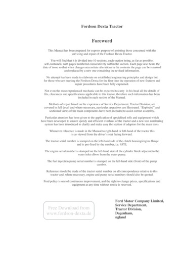
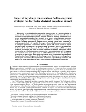
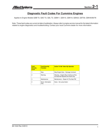
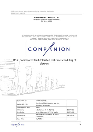
Common non-linear (switching) loads include computers, florescent lighting and variable frequency drives(VFD’s) as mentioned previously. The presence of harmonics in a distribution system results in excessive heatfrom the increased current demands. A load designed to pull 100 amps at full load may draw now 120 amps if theharmonic distortion is high. This additional current can lead to insulation damage and possibly a catastrophicfailure. Excessive zero sequence harmonics will collect back at the transformer, leading to overload and possiblefailure. These high zero sequence currents return to the source through the neutral bus, and, if excessive, cangenerate substantial heat and even fires. In an effort to avoid such catastrophic events, many companies aremodifying their distribution systems. Installing k-transformers, designed to handle the larger loads generated byharmonics, and increasing the mil size of their neutral to accommodate larger current levels are two popularactivities. Though these efforts do nothing to diminish the harmonics, they do reduce the failure risk. Removingthe harmonics requires the installation of filtering mechanisms, such as zero sequence filters.Some of the newer VFDs that utilize IGBTs can exceed line voltage by a tremendous amount in less than amicrosecond. Older class B insulation systems have low tolerance for this rapid rise time and can fail veryquickly. Motors designed for inverter duty are highly recommended when utilizing drives. Excessive cable lengthbetween the drive and the motor can create a high impedance mismatch that contributes to high voltage spikes atthe motor connection box. The drive manufacturer will normally specify the correct cable distance.General guidelines as stated in Table 3.3.1 of IEEE 519-1992, recommend 5% voltage THD for systemsoperating 69kv. They further recommend the individual harmonic voltage distortion to be 3%. Figure 1 showsan example of unacceptable levels of voltage distortion. These high harmonic levels can be seen on the voltagesignal as pulses riding the fundamental frequency (figure 2).Figure 1High 5th and 7th harmonics indicate the presence of a 6 pulse drive influence on the distribution system. Each of
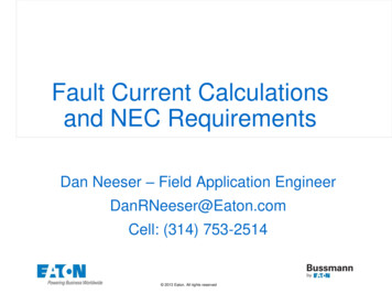
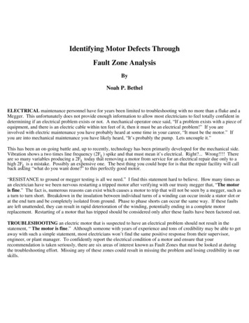
the individual harmonics should be 3% of the fundamental per IEEE 519-1992.Figure 2Figure 2 shows a fundamental 60 Hz voltage signal with 6 pulses occurring throughout each sinewave. Thisresulted from an unfiltered 6 pulse drive connected to the distribution system.Power Circuit: What is a Power Circuit? The power circuit refers to all the conductors and connections that existfrom the point at which the testing starts through to the connections at the motor. This can include circuitbreakers, fuses, contactors, overloads, disconnects, and lug connections. A 1994 demonstration project onindustrial power distribution systems found that connectors and conductors were the source of 46% of the faultsreducing motor efficiency. Many times a motor, although initially in perfect health, is installed into a faulty powercircuit. This causes problems like harmonics, voltage imbalances, current imbalances, etc. As these problemsbecome more severe, the horsepower rating of your motor drops, causing temperatures to increase and insulationdamage to occur. This motor is replaced many times and the failure cycle begins again. As seen in figure 3, highresistance connections resulting in voltage imbalances will reduce the horsepower rating significantly.
Reference: NEMA Standards MG 1-14.35Figure 3One method of detecting high resistance connections is by performing phase to phase resistance testing. On athree phase motor, the three resistance measurements should be nearly identical. If all three reading are exactly thesame, there would be a 0% resistive imbalance. As one or more phases develop a high resistance the resistiveimbalance increases, indicating a fault.Some of the fault mechanisms that cause high resistance connections are:Corroded terminalsLoose cablesLoose bus barsCorroded fuse clipsCorroded contactsOpen leadsDifferent size conductorsDissimilar metals
Figure 4Figure 4 shows three different resistance test points which can be used to determine the actual location of the highresistance connection. Position X is upstream of the fuses. If the resistive imbalance is still high, you may want tomove to position Y, down stream of the contactor. If the imbalance is still evident at position Y, testing at themotor connection box, position Z, will isolate the motor from the power circuit and determine which is theproblem area.Insulation Condition: This refers to the insulation between the windings and ground. High temperatures, age,moisture, and dirt contamination all lead to shortened insulation life. It has been said that if plants would just usethe space heaters available to keep the insulation dry, then doubling the life of our motors would not be out of thequestion.Insulation systems today are better than ever and are able to handle higher and higher temperatures withoutsignificant reduction in life. However, we are still finding ways to destroy our insulation much earlier than shouldbe expected. Keep in mind that although insulation is many times involved in a failure, this fault zone is heavilyinfluenced by other problems. The power circuit for one can heavily influence the insulation. If a high resistanceconnection exists upstream of the motor, which develops better than a 5% voltage imbalance, and we continue torun the motor at its normal Hp rating, we will see a shortened insulation life. Reverse sequence currentsdeveloping rotating magnetic fields in the opposite direction will not only reduce the torque capability, but canallow the temperature to rise out of control and exceed even the 150 0C limit on your class F insulation systems.Was the insulation system the real cause of the motor failure or was it just a symptom? It is easy to diagnose theevident insulation failure as the fault mechanism but it will happen again with a different motor if the problem isnot fixed. Then what will the explanation be?Again, testing with a megger is not going to tell you everything, but it is a good start when it comes to insulationtesting. Something that people often overlook when it comes to the IEEE (Institute of Electrical and ElectronicEngineers) limits on resistance to ground is the reference to 40 0C. Simply megger testing with no regard totemperature will result in resistance to ground readings, which swing heavily from high to low readings, dependingon the temperature of the windings. Temperature correcting the readings will not only meet the IEEE testingrequirements, it will give a much better trend as seen in Figure 5.
Figure 5We must realize that moisture contamination may cause the temperature corrected reading to be invalid. Ensurethe heaters are energized when the motor is not running to prevent this from happening.An insulation test that has fallen out of the spotlight is the Polarization Index test. Applying a constant DCvoltage, in the form of a megger test, for a period of 10 minutes will result in a gradual increase in the resistance toground (RTG) reading. This is a result of charging the insulation system, much like a capacitor, which causes areduction in the absorption current. Per ohms law, I(current) V(voltage) / R(resistance). Therefore, thereduction of this absorption current must result in an increase in the resistance. If we take the ten minute RTG anddivide it by the one minute RTG, a value of 2.0 or higher is considered acceptable by IEEE. Unfortunately, motorswith unstable insulation systems can give values close to or greater then a 2.0, but still be defective.
Figure 6In Figure 6, when the ten minute reading (approximately 600 megohms) is divided by the one minute reading(approximately 300 megohms), the result is 1.94. This nearly meets the IEEE specification as a good insulationsystem, and would probably be accepted in the field. You can see, however, that this insulation system is veryunstable. Always look at the PI Profile and not just the Index.A limiting factor about DC resistance to ground testing is that the DC signal will many times not give the bestevaluation of the true insulation condition. The insulation on a motor is a natural dielectric material. Therefore it is apoor conductor of DC. This is good because you don’t want excessive leakage to ground, but bad in that an insulationsystem in a degraded condition may take a bit longer to be identified using a DC signal or megger. AC however, doesnot allow the dielectric to charge and will pass through the dielectric much easier. This is good because it allows theuse of an AC signal to give much earlier indications of insulation degradation and bad because it can be destructive, aswith an AC Hi-Pot. Low voltage capacitance to ground tests, however, are non destructive and very good earlyindicators of degradation modes in your insulation systems. These values will be read in pico farads (pF) and can beeffectively trended over time.Stator Condition: What is a Stator? When we mention the stator, we are referencing the DC or 3 phase AC windings,insulation between the turns of the winding, solder joints between the coils, and the stator core or laminations.One of the common faults occurring with motor windings is a turn to turn fault. This occurs when the insulationbetween two turns in the same coil breaks down and reduces the coil’s ability to produce a balanced magnetic field.Unbalanced magnetic fields result in vibration, which can then cause degradation of the insula
An insulation test that has fallen out of the spotlight is the Polarization Index test. Applying a constant DC voltage, in the form of a megger test, for a period of 10 minutes will result in a gradual increase in the resistance to ground (RTG) reading. This is a result of charging the insulation system, much like a capacitor, which causes a