Transcription
SDCPUBLICATIONSSchroff Development Corporationwww.schroff.com
AutoCAD 2002 Tutorial: 3D ModelingChapter 53D Surface Modeling Create 3D Surface Models. Apply the available surface modeling techniques. Understand the use of the 2D SOLID command. Using the predefined surface models. Understand the use of 3D FACE command. Use the Hidden Edge option.5-1
5-2AutoCAD 2002 Tutorial: 3D ModelingIntroductionAs illustrated in the previous chapters, there are no surfaces in a wireframe model; itconsists only of points, lines, and curves that describe the edges of the object. Surfacemodeling was developed to provide the surface information that is missing in wireframemodeling. Essentially, defining the skin of a design creates a surface model. Although itis possible to create a surface model without using a wireframe model, in most cases it ismuch easier to create a surface model on top of a wireframe model. In surface modeling,a wireframe model can be used to provide information about the edges and corners sothat the desired faces can be easily positioned and placed.Surface modeling is more sophisticated than wireframe modeling in that surface modelersdefine not only the edges of 3D objects, but also the surfaces. Surface modeling provideshiding, shading, and rendering capabilities that are not available in wireframe modeling.Surface models do not provide the physical properties that solid models provide, such asmass, weight, center of gravity, and so on.The AutoCAD surface modeler defines faceted surfaces using a filled polygon. Thecreated faces of surface models are only planar, which means the surface models can onlyhave approximate curved surfaces. It is important to note that the AutoCAD surfacemodeler does not create true curved surfaces. To differentiate these two types of surfaces,faceted surfaces are called meshes in AutoCAD. Because of the use of facetedapproximation on true curved surfaces, the computer requirements of most facetedsurface modelers are typically much less than that of solid modelers. Faceted surfacemodeling usually provides reasonably good representations of 3D designs with fastrendering and shading capabilities. Faceted surface models are also useful for creatinggeometry with unusual surface patterns, such as a 3D topographical model ofmountainous terrain.AutoCAD 2002 provides three basic methods for creating surfaces – the 2D Solid, 3DFace and Region commands. The three commands were developed parallel to thehistorical development of the different types of computer modelers. 2D Solid: The first generation surface command available in AutoCAD. Usedmostly to fill an area in the sketch plane of the current UCS. This type of surface isnot a true 3D surface. 3D Face: Creates a true 3D planar surface (allowing X, Y and Z coordinates) ofthree-sided or four-sided shape. This is the type of surface developed primarily forcreating faceted surface models. Region: Creates a 2D surface of arbitrary shape from existing 2D entities. Thiscommand creates the most flexible and the most complicated type of surfaceavailable in AutoCAD. This command was developed to allow manipulation of 2Dsurfaces using one of the solid modeling construction techniques, namely, theConstructive Solid Geometry method.
3D Surface Modeling5-3Although all three commands can be used to create planar surfaces, the resulting surfacesare not equal. In fact, the three commands are developed for specific tasks in mind. The2D Solid command is mostly used in 2D drawings to create 2D filled area and theRegion command is designed so that general 2D shapes can be easily transformed intosolid models. The 3D Face command is the only one that is designed specifically forsurface modeling and therefore it is the most suitable for such tasks. The use of the 2DSolid and Region commands in 3D surface modeling can be somewhat awkward and attimes very difficult. Note that the use of the Region command will be focused on in thesolid modeling chapters of this text.As one can imagine, sketching each surface manually can be very time consuming andtedious. AutoCAD also provides additional tools for surface modeling, such asPredefined surfaces, Tabulated surfaces, Ruled surfaces and Revolved surfaces.These tools are basically automated procedures, which can be used to define and createmultiple copies of planar surfaces in specific directions. The principles and concepts usedby these tools are also used in creating solid models, which are covered in chapter sixthrough chapter eight of this text. You are encouraged to re-examine these commandsafter you have finished the solid modeling chapters.In this chapter, the general procedures to create surface models are illustrated. The use ofthe 2D Solid and 3D Face commands are illustrated and differences discussed. We willalso demonstrate the use of the more advanced surface modeling tools. Two wireframemodels, which were created in the previous chapters, will be converted into surfacemodels.
5-4AutoCAD 2002 Tutorial: 3D ModelingStarting Up AutoCAD 20021. Select the AutoCAD 2002 option on the Program menu or select theAutoCAD 2002 icon on the Desktop. Once the program is loaded into thememory, the AutoCAD 2002 drawing screen and the AutoCAD Todaystartup dialog box will appear on the screen.2. In the AutoCAD Today startup dialog box, select the Open Drawings tabwith a single click of the left-mouse-button.3. Click on the V-block.dwg filename to open the V-block wireframe modelcreated in the previous chapter. (Use the Browse option to locate the file if it isnot displayed.) The V-block wireframe model is retrieved and displayed in the graphics window.
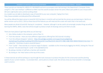
3D Surface Modeling5-5Using the UCS and Surfaces Toolbars1. Move the cursor to the Standard toolbar area and rightclick on any icon of the Standard toolbar to display a list oftoolbar menu groups.2. Select UCS, with the left-mouse-button, to display theUCS toolbar on the screen. The options available in the UCS toolbar allow us to quickly orient and alignthe UCS.3. Move the cursor to the Standard toolbar area and rightclick on any icon of the Standard toolbar to display a list oftoolbar menu groups.4. Select Surfaces, with the left-mouse-button, to display theSurfaces toolbar on the screen. Four groups of options are available in the Surfaces toolbar, which allow us to accessthe surface modeling commands quickly. On your own, move the cursor on top of thedifferent icons and read the brief description of the individual commands in the helpline area.Creating a surface using the 2D SOLID command The first generation surface available in AutoCAD is used to fill an area in the sketchplane of the current UCS. It is therefore necessary to properly orient the UCS prior tousing the 2D Solid command.1. Select the 3 Point UCS in the UCS toolbar. The 3 point UCS option allows us to specify thenew X-axis and Y-axis directions to align theUCS.2. In the command prompt area, the message “Specify neworigin point 0,0,0 :” is displayed. Pick the lower-rightcorner of the front face of the wireframe model as shown.
5-6AutoCAD 2002 Tutorial: 3D Modeling3. In the command prompt area, the message“Specify point on positive portion of X-axis:”is displayed. Pick the adjacent corner towardthe right side of the model as shown.4. In the command prompt area, themessage “Specify point on positiveportion of X-axis:” is displayed. Pick theright corner of the inclined plane asshown. The new UCS is aligned to thevertical inclined plane as shown.5. Select 2D Solid in the Surfaces toolbar.6. Place the first corner-pointof the 2D solid at the originof the new UCS.
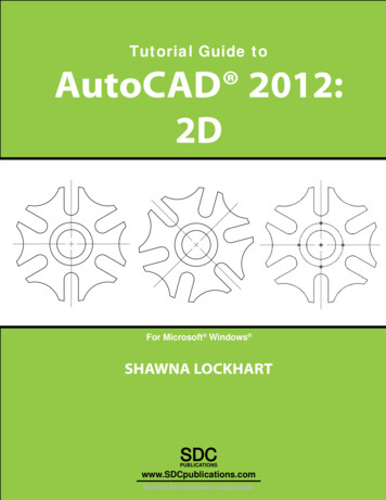
3D Surface Modeling5-77. In the command prompt area, themessage “Specify second point:” isdisplayed. Pick the bottom-right cornerof the inclined plane as shown.8. In the command prompt area, themessage “Specify third point:” isdisplayed. Pick the corner directlyabove the origin of the UCS as shown. The 2D Solid command requires the third point to be specified diagonally opposite tothe second point. This seemly strange way of specifying the third corner wasestablished when the 2D Solid command was first introduced back in the mid-1980s.Note that the 3D Face command, the second-generation surface command inAutoCAD, does not follow this convention.9. In the command prompt area, themessage “Specify fourth point or[Exit]:” is displayed. Pick thecorner directly above the secondpoint we selected as shown in thefigure.10. Inside the graphics window, rightmouse-click once to end the 2DSolid command. The 2D Solid command allows the creation of three-sided or four-sided filledpolygons, which can be used to represent faces of surface models. Note that in theabove steps, we could accept the three-sided polygon after defining the third corner.
AutoCAD 2002 Tutorial: 3D Modeling5-8Using the Shade Toolbar1. Move the cursor to the Standard toolbar area and right-click on any icon ofthe Standard toolbar to display a list of toolbar menu groups.2. Select Shade, with the left-mouse-button, to displaythe Shade toolbar on the screen.HiddenShading options2D Wireframe3D Wireframe 2D Wireframe: Displays the objects using lines and curves to represent theboundaries of objects created. Linetypes and lineweights are visible with thisoption. Note that this is the default AutoCAD display mode. 3D Wireframe: Displays the objects using lines and curves to represent theboundaries of objects created. Displays a shaded 3D user coordinate system(UCS) icon. Note that linetypes and lineweights are not visible with this option. Hidden: Displays the objects using the 3D wireframe representation with linesthat are located behind surfaces and solids removed. Flat Shaded: Creates a shaded image of polygon faces and solids. The shadedobjects appear flatter and less smooth than Gouraud Shaded objects. Gouraud Shaded: Creates a shaded image of polygon faces and solids usingthe Gouraud method. This mode generates an image that gives the objects asmooth and realistic appearance. Flat Shaded, Edges On: Combines the Flat Shaded and 3D Wireframeoptions. The objects are flat shaded with the wireframe edges showing through. Gouraud Shaded, Edges On: Combines the Gouraud Shaded and 3DWireframe options. The objects are Gouraud shaded with the wireframe edgesshowing through.
3D Surface Modeling5-93. In the Shade toolbar, click on the Gouraud Shadedicon to display the shaded image of the model. Thereexists only one surface in our model. The surface wascreated with the 2D Solid command.4. Click on the 3D Orbit icon in the Standard toolbar.5. Inside the arcball, press down theleft-mouse-button and drag it to rotatethe model freely in 3D space. Observe the display of the shadedsurface in contrast to the 3Dwireframe edges that are locatedbehind it.6. On your own, reset the display to theSE Isometric View beforecontinuing to the next section.7. In the UCS toolbar, select the World UCS. Thisoption resets the UCS to align to the world coordinatesystem.
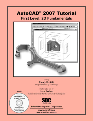
5-10AutoCAD 2002 Tutorial: 3D ModelingCreating a surface using the 3D FACE command The second generation of surface command made available in AutoCAD was the 3DFace command. The 3D Face command can be used to create true 3D planarsurfaces by allowing the X, Y and Z coordinates of the corners to be selectedindependently of the current UCS. The created polygon can be a three-sided or foursided shape. This command is the primary construction tool for surface modeling inAutoCAD.1. Select the 3D Face in the Surface toolbar.2. In the command prompt area, the message“ 3dface Specify first point or [invisible]:” isdisplayed. Pick the lower-right corner of thevertical inclined face of the model as shown.3. In the command prompt area, the message“Specify second point or [invisible]:” isdisplayed. Pick the adjacent corner above theprevious selected corner of the verticalinclined face as shown.4. In the command prompt area, themessage “Specify third point or[invisible]:” is displayed. Pick theadjacent corner of the right-verticalface of the model as shown.5. In the command prompt area, the message“Specify fourth point or [invisible] Createthree-sided face :” is displayed. Pick the cornerbelow the last selected corner as shown.
3D Surface Modeling5-116. In the command prompt area, the message“Specify third point or [invisible] exit :” isdisplayed. Pick the back corner of the modelas shown.7. In the command prompt area, the message“Specify fourth point or [invisible] Createthree-sided face :” is displayed. Pick theback corner of the model as shown. Note that this surface is created independentof the UCS and two corners of the previousface were used to position this face.8. Inside the graphics window, right-mouse-click to activate theoption menu and select Enter with the left-mouse-button to endthe 3D Face command.9. In the Shade toolbar, click on the Hidden icon todisplay the model with hidden lines removed.10. Click on the 3D Orbit icon inthe Standard toolbar.11. Rotate the model in 3D spaceand examine the constructedsurface model. Reset the display to SE Isometric View before proceeding to the next section.
5-12AutoCAD 2002 Tutorial: 3D ModelingCreating a surface of irregular shape The 3D Face command allows us to create three-sided or four-sided polygons. Forsurfaces of irregular shape, the Invisible Edge option is available in conjunction withthe 3D Face command. Note that the Invisible Edge option cannot be applied topolygons created by the 2D Solid command.1. Select the 2D Wireframe in the Shade toolbar. The 2D Wireframe command resets the display to the defaultAutoCAD display mode2. Select the 3D Face in the Surface toolbar.3. In the command prompt area, the message“ 3dface Specify first point or [invisible]:” isdisplayed. Pick the top-right corner of themodel as shown.4. In the command prompt area, the message“Specify second point or [invisible]:” isdisplayed. Pick the top-front corner of themodel as shown.5. In t
5-8 AutoCAD 2002 Tutorial: 3D Modeling Using the Shade Toolbar 1. Move the cursor to the Standard toolbar area and right-click on any icon of the Standard toolbar to display a list of toolbar menu groups. 2. Select Shade, with the left-mouse-button, to display the Shade toolbar on the screen. 2D Wireframe: Displays the objects using lines and curves to represent the boundaries of objects .