Transcription
Owner'sManualModel 8SRT2139.53650SRT139.53660SRT1139.53834SRT3For Residential UseOnlyCRAFTSMAN GARAGE DOOR OPENERCaution:Read and follow allsafety rules andoperating instructionsbefore first use of thisproduct.Fasten the manualnear the garage doorafter installation. Safety Precautions Assembly Installation Adjustment Care and Maintenance Operation Troubleshooting Parts ListComplies with UL 325regulations effectiveJanuary 1, 1993Sears,Roebuckand Co., HoffmanEstates,IL 60179U.S.A.
ContentsPageA reviewof safety alert symbols.2You', need tools.3Safety informationregardinggarage door locksand ropes.3Testingyour garage doorfar sticking,bindingand b Jance.3Illustretionof sectionaldoor installation.4Illustretionof one-piece door installation.5Carton inventory.6Hardware inventory.7Assembly section - pages 8 - 11AssembleT-reii.8Attachcable pulleybracket.8Installtrolley.9Fasten T-reitto opener .9Installchain/cable .10Attach sprocketcover.10"tightenthe chainand cable .11Installation section - pages 11 -27Installationsafety instructions.11Determine headerbracket locationSectionaldoor.12One-piece door.13Installthe headerbracket .14Attachthe T-rail to header bracket.15Positionthe opener.16Hang the opener.17Installthe doorcontrol.18ContentsPageInstallthe lightand lens .19Attach emergencyrelease ropeand handle.19Electricalrequirememts.20Safety reversingsensorinformation.21Installthe safety reversingsensor .22, 23Fastendoor bracket (sectionaldoor) .24Fastendoor bracket(one-piecedoor).25Connectdoor arm to trolley(sectionaldoor).26Connectdoor arm to trolley(one-piecedoor) .27Adjustment section - pages 28 - 30Travel limitadjustments.28Forceadjustments.29Test the safety reversingsensor .30Test the safety reverse system .30Operationsafety instructions.31Care ofyour opener.31Maintenanceschedule .31Operationof youropener .32Receiverand remote controlprogramming.33Having a problem?.34, 35Repair parts, railassembly.36Repair parts, installation.36Repair parts,opener assembly.37Accessories.38Index .39How to order repair parts.40Maintenanceagreement.40Warranty .40Start by reviewing these important safety alert symbolsWhen you see these Safety Symbols on the following pages, they will alert you to the poeslblllty ofserious injury or denthff you do not comply with the corresponding instructions. The hazard maycome from something mechanical or from electric shock. Rend the instructions en you see this Safety Symbol on the following pages, It will alert you to the possibilityof damageto your garage door and/or the garage door opener if you do not comply with the correspondinginstructions. Read the instructions carefully.IACAUTIONThis garage door opener is designed and tested to offer safe service provided it is installed, operated,maintained and tested in strict accordance with the safety Instructions contained in this manual.2I
You'll Need ToolsDuring assembly, installationand adjustment of the opener, instructionswill call for hand tools DnlLSawCuttersClaw3/16", 5/16" and5/32" Dn l BitsHammerPliersStepladderAdjustableEnd WrenchCAUTIONWARNINGTo avoid damage to the garage door andopener, disable locks before installing andoperating the opener. Use a wood screw or nailto hold locks in the "open" (unlocked) position.Operation at other than 120V 60 Hz will causeopener malfunction and damage.An unbalanced garage door might not reversewhen required and someone under the doorcould be seriously injured or killed.If your garage door binds, sticks or is out ofbalance, call for professional garage doorservice. Garage doora, door springs, cables,pulleys, brackets and their hardware are underextreme tension and can cause serious injuryor death. Do not fry to loosen, move or adjustthem yourselflRopes left on a garage door could causesomeone to become entangled and killed.Remove all ropes connected to the door beforeinstalling and operating the opener,Before you begin, complete the following test tomake sure your door Is balanced, and Is notsticking or binding: Uft the door about halfway as shown. Release thedoor. It should stay in place, supported entirely byits springs. Raise and lower the door to see if there is anybinding or sticking.Identify the type and height of your door and anyspecial conditions that exist and any additionalmaterials that may be required by referring to thelists on page 4 or page 5.ONE-PIECE DOOR3
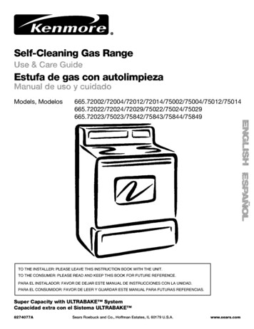
ISECTIONALDoor InstallationIBefore you begin, survey your garage area tosee whether any of the conditions below applyto your Installation.Horizontal and vertical reinforcementis needed for lightWeight garage doors(fiberglass, steel, aluminum, door with grass panels, etc.).See page 24 for details.HeaderFINISHED CEIUNGSupao bracket &is required.See page 17.Slac in Chainis NormalGarageTensmnWheDoor is ClosedWallExtension SpringFloor mustacrossSafetyReversingbe ravelwidth of dOOrClosed PositionSensorBH ea( d: Bc:b e 3"rolleyBased on your particularrequirements, there areseveral installationsteps which mightcall Iormaterials and/or hardware not includedin the carton. Step 1, page 12 - Look at the wall or ceilingabovethe garage door. The header bracket mustbesecurely fastened to structuralsupports. Step 5, page 17 - Do you have a finished ceiling inyour garage? If so, a supportbracket andadditional fastening hardware may be required. Safety reversing sensor, page 21 - Dependingupon garage construction,wood blocks may needto be fastened to mounting locationsbeforesensors are installed. Step 10, page 22 - Alternate floor mounting of thesafety reversing sensor will require hardware notprovided. Step 11, page 24 - Do you have a steel, aluminum,fiberglass or glass panel door? It so, horizontaland vedicel reinforcementis required. Look at the garage door where it meets the lloor.It must close on the floor all the way across.Other-wise, the safety reverse system may notwork properly. See page 30. Floor or door shouldbe repaired.Rail AssemblyCable Pulley].,IoL--EmergencyReleaseRope & HandlesCurvedDoor : "HeadeWallGarageArmDoor Bracket. The opener can be installed within 2 feet of the leftor right of the door center if there is a torsion springor center bearing plate in the way of the headerbracket or door bracket area. ff your door hasextension spdngs, the opener must be installedin the center of the door. See pages 12 and 24. Do you have an access door in addition to thegarage door? If not, Model 53702 EmergencyKey Release is required. See page 38. It your door is more than 7 feet high, see the longerrails available on page 38.You may find it helpful to refer back to this page as you proceed with the installationof your opener.
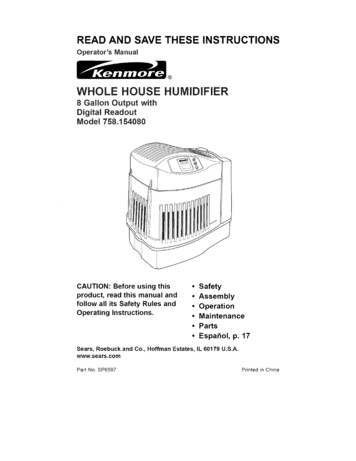
IONE-PIECEDoor InstallationIBefore you begin, survey your garage area tosee whether any of the conditions below applytO your Installation.One-Piece Door Without Track/FINISHED CEILINGSupp . our e&lastinghardware is required,Slac ksChanom nintenwtN nSmnSeepage17garage door is dosed,/zleGapof door rnust not exceed 1/4".Safety Reversing SensorBased on your particularrequirements, there areseveral installationsteps which mightcell formaterialsand/or hardware not includedin the carton.One-PieceDoor With Track Step 1, page 13 - Look at the wall or ceiling abovethe garage door.The header bracket mustbesecurely fastened to structuralsupports. Step 5, page 17 - Do you have a finished ceiling inyour garage? If so, a supportbracket andadditionalfastening hardware (not provided) maybe required. Safety reversing sensor, page 21 - Depending ongarage construction,wood blocksmay need to besecurelyfastened to mounting locationsbeforesensors are installed. Step 10, page 22 - Alternate floor mounting of thesafety reversing sensor will require hardware thatis not provided. Step 11, page 25 - Generally, a one-piece doordoes not require reinforcement.If your door islightweight, you can refer to the informationrelatingto sectional doors on page 24. Step 11, page 25 - Depending on your door'sconstruction,you might need additional mountinghardware for the door bracket. Do you have an access door in addition to thegarage door? If not, Model 53702 EmergencyKey Release is required. See page 38. The gap between the bottom of the garagedoor and the floor cannot exceed 1/4".Otherwise, the safety reverse system may notwork properly. See page 30. The floor or the doorshouldbe repaired.Safetyacro4ss width of doorReversing SensorClosed PositionCableCableTrolleyChain, BracketT-railBracketDoorStraightDoorArmReleaseRope & HandleYou may find It helpful to refer back to this page asyou proceed wIth the installation of your opener.
Carton InventoryYour garage door opener is packaged in two cartonswhich contain parts illustratedbelow. Accessories willdepend on model purchased. If anything is missing, carefully check the packing material. Parts may be "stuck"in the foam. Hardware for assembly and installationis shownon page 7.MOdels53335 (1),53645 {2), 53646(2),S364S(2), 5365O(2), S3660( ), 53S34 (2),Three*Function Remote Controlwith Visor ClipModels 53335,53648, 53660Models 53645, 53646DOOrControl ButtonCablePulley BracketModels 53650, 53834StandardControl Console2*ConduetorPremiumControl ConSOleModel 53645Multi-FunctionUght LensCenter Sectionw"it "w " edT o,, Sprocket CoverSafety Reversing SensorMounting BracketWith Square Holes 12)' 7in Dispensing CartonHanging BracketsArm SactionCurved DoorSalety Reversing SensorMounting BracketWilh Slot (2)Safety LabelsandLderature(1 Sanding Eye and 1 Receiving Eye)with2-Conductor White & White/Black Bell WireattachedStraight Ooo,Arm Section
Separate all hardwarefrom the packagesin the rail carton and the openershown below, for the assemblyand installationprocedures.AssemblyWashered Screw5/16"-18xl/2' (2)(mounted in Opener)carton,asHardwareHex Screw5/16'-18x7/8" (3)Nut5/16'-18 (5)Carriage Bolts1/4"-20xl/2" (4)Master Link (2) Lock Washer5/16' (4)Lock Nut1/4'-20x7/16 /I/ OTrolley Threaded Shaft (1)Installationl'l'l'l'Jo'J:!0Hardware@5/16"-9xl -5/8" (2)RingFastener (3)HandleNut 5/16"-18 (6)lllllllll[llllllllllllLag Screw5/16"-18x1 7/8' 12)Hex Screw5/16"-18x7/8" (4)insulatedStaples (10)Lock Washer 5/16" (6)I( ,',','5/, 6Ca.SaS .2ge, lt(2)6ABSCxl"re 2)Dry Wall Anchors (2)RopeoClevis Pin5/16"x2-3/4" (1)oClevis Pin5/16"x1" (1)Clevis Pin5/16"xi 1/4" (1)Safety Reversing SensorInstallation Hardware 1/4 x1-1/2 (4)Carriage Bolts114"-20xl/2 (4),IIIIIIIIIIIII I IIIIIIIII [ I IIH DHex Screw1/4 20x1-1/2"(2)Screw#10-32x5/8' (4)7Lock Nut1/4'-20 (4)Wing Nut (2)@LOCkNut#10x32 (4)InsulatedStaples (20)
Assembly Section: Pages 8 - 11To avoid installationAssemblydifficulties,do not run the garagedoor openeruntil instructedto do so.Make sure bolt necks areStep 1seatedIn thesquare,holesand ndwrongviews).ImproperassemblycanAssemble the T-rail & Attachthe Cable Pulley Bracketcause jerky trolley Align the 3 T-rail sections on a flat surface exactlyas shown. The end sections are identical. Makesure the "arrow label" on the center section ispointing toward the door.operation,noiseand/orURightWrongnuisance door reversals.T-RAiL BACK(TO OPENER)Insert the carriage bolts so the square bolt necksseat in the square holes in the T-rail end sectionsand pass through the round holes in T-rail centersection. Assemble lock nuts, ensure alignment andtighten.1/4" Lock NutT-rail(End Section)QBraceT-rail(Center Seclion)If T-reil Is not assembled IEXACTLYas shown, trolley ]will not travel smoothlyIalong lengl 'tof rail or it willhit againstthe nuts.T-rail(End Section)f Carnage BoltHardware Shown Actual Size\Cable pulley bracketattaches to FRONTEND of T-fair Square CarnageBolt HolesLock Nut1/4" - 20 x 7116"Carnage Bolts1/4" - 20 x 1/2"T-RAIL FRONT(TO DOOR)Hex Screw5/16" - 18 x 7/8"Positionthe cable pulleybracket on the frontend of theT-rail as shown.Fasten securelywiththe hardware.Nut5/16" - 18Lock Washer5/16"Hex Screws5/16'- 18x7/8"ORight5/16'8WrongWhen tighteningthe screws, besure to keepbracket parallelto the rail.Otherwise, therail may bowwhen opener isoperated.
AssemblyIStep 2Install the Trolley on the T-railHardware ShownActual Size Attach the threaded shaft to the trolley with thelock washer and nuts as shown.LoCk WasherNut5/16 5/16" - 18Lock WasherOuter Nut5/16"TroileTemporary StopScrewdriver As a temporary stop, insert a screwdriver into thehole in the front end of the T-rail. Slide the trolley assembly along the rail to thescrewdriverstop.If trolley hits against any nuts on the T-ralt, thebolts and nuts were attached from the wrongside and must be reposltioned. Review Step 1.AssemblyFastenIStep 3the T-raft to the Opener Place the opener on packing material to protectthe cover. For convenience, put a supportunderthe cable pulley bracket.in theof the opener.i mountedRernove the(2)top5/16"-18xl/2"washered screwsAlign the holes in the back section of the T-rail withthe holes in the opener. Fasten the rail with the (2) washered screwspreviously removed. Tighten securely.Remember to use only these screws! Any otherscrews will cause serious damage to the opener. Insert a 5/16"-18x7/8" hex screw intothe coverprotectionbelt hole in the T-rail as shown. Tightensecurely with a 5/16" lock washer and nut,NOTE: This screw prevents trolley over-travel.Keep a 2" minimum between the trolley and thisscrew when adjusting travel limits (see page 28).HardwareHex Screw16'- 18 x 718"Shown Actual SizeNut5/16"-Lock Washer185/16'CAUTIONTo fasten rail, use only those screws mountedIn the top of the opener. Any other screws willcause serious damage to the opener.Washered Screw5/16"-18xl/2"Hex Screw5/16"-18X7/8'CoverProtection5/16"*18
Assembly Step 4WARNINGInstall the Chain/Cable &Attach the Sprocket CoverDispensingSerious Injury can result If fingers becomeentangled In moving opener sprocket. Attachsprocket cover securely. Never operate openerwhile your hand Is near the opener sprocket.CartonFigureLeave Chain and CableInsole DLspensing2OpenerSprOcketKeep Chain and CableTaut When Dispensing Detach the cable loop from the carton and fasten itto the trolley with a master linkfrom the hardwarebag. See master link procedure, Figure 1.Figure With the trolley against the screwdriver,dispensethe cable around the pulley. Proceed back around the opener sprocket,Figure 2. Be sure sprocketteeth engage thechain. Continue forward to the trolleythreaded shaft, Figure 3.MasterLink Use the second master link to connectClip-OnSpnngMasterc pOnspringMasterUnkCap"FlatEndofTrolleyThreadedthe chain to the flat end of the shaft.Check to make sure the chain Isnot twisted. Remove the ableLoopPin NOtchTrolleyLink Bar:abJeMasterFigure 1PulleyMaster Link Procedure:install Chain and CableIn "PnisDirectionPush pins of master link barthrough cable loop and hole infront end of trolley. Push capover pins and past notches.Slide clip-on spdng over capand into notches until bothSprocketCoverBack TabSlatpins are securely ocked.,oFront TabTop at OpenerSlotTo attach the sprocketcover: Insert the back tab in the opener slot. Squeeze thecover slightly and insert the front tab in the slot onthe mounting plate.Mounting10
AssemblyStep 5Tighten the Chain & CableILockWasherOuter Nut Spin the inner nut and lock washer down thethreaded shaft, away from the trolley.Inner Nutz: :z:zT Tighten Outer Nut To tighten the chain, turn outer nut in the directionshown. As you turn the nut, keep the chainfrom twisting.I n r NUt When the chain is approximately 1/2" above thebase of the T-rail at its midpoint, re-tighten theinner nut to secure the adjustment.eTo TightenTrollSprocket noise can result if chain is either tooloose or too tight.ChainWhen installation is complete, you may notice somechain droop with the door closed. This is normal. Ifthe chain returns to the position shown when thedoor is open, do not re-adjust the chain.IIIIIII!ItIIflIIIIII1/2 InchIBase of T-railNOTE: During future maintenance, ALWAYSpull the emergency release handle to disconnecttrolley before adjusting chain.You have now finished assembling your garage door opener.warnings before proceeding to the installation section:IMPORTANT INSTALLATIONPlease read the followingINSTRUCTIONSTo reduce the risk of severe injury or death to persons:1. READ AND FOLLOWALL INSTALLATIONINSTRUCTIONS.2. Install only on a properly balanced and lubricated garage door. An improperly balanced doormay not reverse and could result in severe injury or death. Repairs to cables, spring assembliesand other hardware must be made by a professional service person before installing opener.3. Disable all locks and remove all ropes connected to the garage door before installing the opener.Ropes connected to a garage door can cause entanglement and death.4. It possible, install door opener 7 feet or more above floor with the emergency release handlemounted 6 feet above the floor.5. Do not connect the opener to power source until instructed to do so.6. Locate the Door Control within sight of the door at a minimum height of 5 feet where smallchildren cannot reach and away from all moving parts of the door.7. Install the User Safety Instruction Label on the wall adjacent to the door control and theMaintenance Instruction Label in a prominent location on the inside of the garage door.8. Upon completion of the installation, the door must reverse when it comes in contact with aone-inch high object or a 2x4 laid flat on the floor.9. Do not wear watches, rings or loose clothing while installing or servicing an opener. Jewelry orloose clothing can be caught in the mechanism of the garage door or the opener.11
InstallationInstallationDetermineSection:Step 1HeaderBracketLocationIf the header bracket is not rigidly fastened toa structural support on the header wall orceiling, the safety reverse system may notwork properly (see page 30). The door mightnot reverse when required, and could causeserious injury or death.Installation procedures vary according togarage door types. Follow the instructionswhich apply to your cturalII1-II I IL,III.IIYP -- .- -----SupportsIItLII;I fI1 1 IIIII IIII IIII/IIll!l; e , gI --I !tl:lG ' e'i lllIitli,iII11II ILIIIffIIIIIII II IIllI lII tFfIIIII Lt tI!1IllIIY/TIllRemember, you can fasten theheader bracket within 2 feet of theleft or right of the door center onlyifI!]IIIIllabovethedoor,IIIIII I Close the door and mark the insidevertical centerline of the garage door. Extend the line onto the header wallL.[]'1 [1I]u jII I!! IF1 -- L--J iThe garage door springs, cables, pulleys,brackets and their hardware are under extremetension. Do not attempt to loosen, move oradjust them yourself.Serious personal injuryor death could result. Call for professionalgarage door service.--2x4!l IPages 12 - 27atorsionspringorcenterbearingplate is in the way; or you can attachit to the ceiling (refer to page 14)when clearance is minimal. (It maybemountedonthewallupsidedownif necessary, to gain approximately!1 L1/2".)IIfyouneedtoinsta//theheaderbracketII.on a 2x4 (on wall or ceiling), use lagscrews (not provided) to securely fastenthe 2x4 to structural supports as shownhere and on page 13.CeilingHeader Open your door to the highestpoint of travel as shown. Drawan intersecting horizontal lineon the header wall 2" abovethe high point. This height willprovide travel clearance for thetop edge of the door.Door clearance brackets areavailable for sectional doorswhen headroom clearance isless than 2". See accessorypage 38.WallTrackTrackHighestPointof Travelof TravelDoorSectional doorwith curved trackProceedHeaderto Step 2, page 14.12One-piece doorwith horizontal track
Read the Safety instructionson page 12. They also apply to doors withouttracks.Header WallVerticalCentedine2x4 Close the door and mark theinside vertical centerline ofyour garage door. Extend theline onto the header wallabove door.If headroom clearance isminimal, you can install theheader bracket on the ceiling.See page 14.OPTIONAL CEILING MOUNTFOR HEADER BRACKETIf you need to instal/theheader bracket on a 2x4 (onwail or ceiling), use lag screws(not provided) to securelyfasten the 2x4 to structuralsupports as shown.Header Wall/Highest Pointof Travel/DoorWallof TravelHeaderHighest Point1IiJambHardwareOne-piece door without trackjamb hardware Open your door to the highestshown. Measure the distancedoor to the floor. Subtract thedoor. Add 8" to the remainder.One-piece door without trackpivot hardwareEXAMPLEpoint of travel asfrom the top of theactual height of the(See Example).Distance from top of door(at highest point of travel) to floor . 92"Actual height of door . -88"Remainder .4"Close the door and draw an intersecting horizontalline on the header wall at the determined height.If the total number of inches exceeds the heightavailable in your garage, use the maximumheight possible, or refer to page 14 for ceilinginstallation.ProceedAdd . 8"Bracket height on header wall .12"(Measure UP from top of CLOSED door.)to Step 2, page 14.13
Install the Header Bracket"InstallationStep 2You can attach the header bracket either to thewall above the garage door, or to the ceiling.Follow the instructions which will work best foryour particular requirements,IFasten the Header Center the bracket on the vertical guideline withthe bottom edge of the bracket on the horizontalline as shown (with the arrow pointing toward theceiling).Bracketto the Wall Mark either set of bracket holes (do not use theholes designated for ceiling mount). Drill 3/16" pilotholes and fasten the bracket securely to a structuralsupport with the hardware provided.WallMounting HolesHeaderWallLag e nail hole is for positioningonly. You must use lag screws tomount the header bracket.OptionalWall MountingHolesJGarageDoorHighestPoint of TravelHardware Shown Actual Sizeq o01rewI VerticalCenterLine(of Garage Door)5/16"-9xl-5/8"Fasten the HeaderBracketto the Ceiling Extend the vertical guideline onto the ceiling asshown. Center the bracket on the vertical mark, no morethan 6" from the wall. Make sure the arrow ispointing toward the wall. The bracket can bemounted flush against the ceiling when clearanceis minimal. Mark holes designated for ceiling mount only. Drill3/16" pilot holes and fasten bracket securely to astructural support with the hardware provided.Ceiling MountingDoorSpdngHolesHeaderWallThe nail hole is for positioning only,You must use lag screws to mountthe header bracket 14
InstallationAttachStep 3the T-rail to the HeaderBracket Position the opener on the garage floor below theheader bracket. Use packing material as aprotective base.If the door spring is in the way you'll need help.Have someone hold the opener securely on atemporary support to allow the T-rail to clear thespring.HeadeBrackelCable Position the cable pulley bracket against the headerbracket.Bracket Align the bracket holes and join with a clevis pin asshown. Insert a ring fastener to secure.Ring FastenerHeader BracketClevis Pin5/16"x2-3/4 'CablePulleyBracketDoor\--Hardware Shown Actual Sizeo]Clevis Pin5/16" x 2 3/4'TemporarySupport Ring Fastener15
InstallationPositionStep 4CAUTIONthe OpenerFollow instructionstype as illustrated.To preventdamage to steel, aluminum,fiberglass or glass panel doors, do not rest theopener on the door without using a 2x4.which apply to your doorSECTIONALDoor & ONE-PIECEDoor with Track IA 2x4 laid flat is convenient for setting an idealdoor-to-T-rail distance.T-rail Raise the opener onto a stepladder.2x4You will need help at this point if the ladder isnot tall enough, Open the door all the way and place a 2x4 laid flaton the top section beneath the T-rail.Doorif the top panel hits the trolley when you raisethe door, pull down on the trolley release arm todisconnect the inner and outer sections. Thetrolley can remain disconnected until Step 12 iscompleted,Trol seStepladderArmHeaderBracket With the door fully open and parallel to the floor,measure the distance from the floor to the top ofthe door.Top of OpenerI Using a stepladder as a support, raise the openerto the same distance as the door from the floor (itwill be at a slight angle as shown). The top of the door should be level with the top ofthe opener. Do not position the opener more than2" above this point.Stepladder16
InstallationStep 5Hang the OpenerTwo representative installations are shown.Yours may be different. Hanging brackets shouldbe angled, Figure 1, to provide rigid support. Onfinished ceilings, Figure 2, attach a sturdy metalbracket to structural supports before installing theopener. The bracket and fastening hardware are notrovided. See accessory page 38.Figure 1Supports Measure the distance from each side of the openerto the structural support. Cut both pieces of the hanging bracket to requiredlengths.Screws5/15/-18xl-7/8' Drill 3/16" pilot holes in the structural supports.Measure Attach one end of each bracket to a support with5/16"-18xl -7/8" lag screws. Fasten the opener to the hanging brackets with5/16"-18x7/8" screws, lock washers and nuts. Check to make sure the T-rail is centered over thedoor (or in line with the header bracket if thebracket is not centered above the door).5/16'-18x7/8" Screw16" Lock Washer5/16"-18 Nut Remove the 2x4. Operate the door manually. If thedoor hits the rail, raise the header bracket.Figure 2HiddenSupport IGrease the top and underside of therail surface where the trolleyslides. A tube of grease is /supplied././ ". f-Hardware Shown Actual SizeI!!l!l!;LI!5/16'18xl-7/8"HexScrew18x7/8"Nut 5/16"-18LockWasher5/16"17/o o o o.5/16" t-- FINISHED CEILING -Lag Screws5/16 -18xl-7/5/"Bracket5/16'-/" "18."-5/16"-.u,Lock Washer
i,InstallationInstallStep 6the Door ControlDo not connect to live electrical wiring. Connectonly to 24 Volt low voltage wires. Connection tolive wires or higher voltage may cause setfousinjury from shock, burn or electrocution.Children operating or playing with a garagedoor opener can injure themselves or others.The garage door could close and causeserious injury or death.Install the door control (or any additional pushbuttons) out of the reach of children and awayfrom all moving parts of the door and doorhardware, but where the garage door is visible.Do not allow children to operate the pushbutton(s) or the remote control(s).A moving garage door could injure someoneunder it. Activate the opener only when thedoor is properly adjusted, you can see it clearly,and there are no obstructions to door travel.Locate the door control within sight of the doorat a minimum height of 5 feet where smallchildren cannot reach, and away from all movingparts of the door and door hardware.The door control is typically attached directly to thewall. If installing into drywall, drill 5/32" holes anduse the anchors provided. For pre-wirad installations'as in new home construction.), Console modelsmay be mounted to a standard single gang box"Figure 2).1. Strip 1/4" of insulation from one end of the bellwire and connect it to the two screw terminals onthe back of the door control: white to 2 andwhite/red to 1.2. Door Control Button: Fasten securely with6ABx1-1/2" screws.Console Model: Pry off cover along one sidewith a screwdriver blade
Owner's Manual Model No. 139.53335SRT3 139.53645SRT3 139.53646SRT2 139.53648SRT2 139.53650SRT 139.53660SRT1 139.53834SRT3 For Residential Use Only Caution: