Transcription
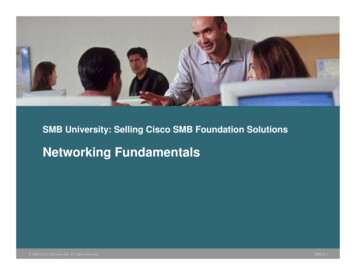
Networking FundamentalsPart of the SolarWinds IT Management Educational SeriesV o l u me 6IP AddressingThis paper examines IP Addressing with an emphasis onunderstanding how address are allocated and managed.As part of the Network Fundamentals series, it is meantto be an introductory level paper.
Networking Fundamentals » Volume 6, IP AddressingPage 2Table of ContentsSection 1 — IP Terminology and Number Formats . . . . . . . . . . 3Section 2 — IPv4 Classful IP Addressing . . . . . . . . . . . . . . . . . . 4Private IP Addresses . . . . . . . . . . . . . . . . . . . . . . . . . . . . . . . . . . 4Network Address Translation (NAT) . . . . . . . . . . . . . . . . . . . 5Section 3 —Classless Internet Domain Routing (CIDR) Addressing . . 6Requesting a Registered CIDR Block . . . . . . . . . . . . . . . . . . . 6Section 4 — Device IP Address Configuration . . . . . . . . . . . . . 8Dynamic Host Configuration Protocol (DHCP) . . . . . . . . . 13Section 5 — IPv6 . . . . . . . . . . . . . . . . . . . . . . . . . . . . . . . . . . . . . . .Address Formats . . . . . . . . . . . . . . . . . . . . . . . . . . . . . . . . . . . . .Special Address Types . . . . . . . . . . . . . . . . . . . . . . . . . . . . . . . .Other Notable IPv6 Features . . . . . . . . . . . . . . . . . . . . . . . . . .9999Section 6 — Review . . . . . . . . . . . . . . . . . . . . . . . . . . . . . . . . . . . . 10Related SolarWinds Products . . . . . . . . . . . . . . . . . . . . . . . . . . . 11About SolarWinds . . . . . . . . . . . . . . . . . . . . . . . . . . . . . . . . . . . . . 12About the Author . . . . . . . . . . . . . . . . . . . . . . . . . . . . . . . . . . . . . . 12Copyright 1995–2010 SolarWinds. All rights reserved worldwide. No part of this document may be reproduced by any means nor modified, decompiled, disassembled, published or distributed, in whole or in part,or translated to any electronic medium or other means without the written consent of SolarWinds. All right, title and interest in and to the software and documentation are and shall remain the exclusive propertyof SolarWinds and its licensors. SolarWinds Orion , SolarWinds Cirrus , and SolarWinds Toolset are trademarks of SolarWinds and SolarWinds.net and the SolarWinds logo are registered trademarks ofSolarWinds All other trademarks contained in this document and in the Software are the property of their respective owners.SOLARWINDS DISCLAIMS ALL WARRANTIES, CONDITIONS OR OTHER TERMS, EXPRESS OR IMPLIED, STATUTORY OR OTHERWISE, ON SOFTWARE AND DOCUMENTATION FURNISHED HEREUNDERINCLUDING WITHOUT LIMITATION THE WARRANTIES OF DESIGN, MERCHANTABILITY OR FITNESS FOR A PARTICULAR PURPOSE AND NONINFRINGEMENT. IN NO EVENT SHALL SOLARWINDS, ITSSUPPLIERS OR ITS LICENSORS BE LIABLE FOR ANY DAMAGES, WHETHER ARISING IN TORT, CONTRACT OR ANY OTHER LEGAL THEORY EVEN IF SOLARWINDS HAS BEEN ADVISED OF THE POSSIBILITYOF SUCH DAMAGES.Document Revised: Oct 1, 2010
Networking Fundamentals » Volume 6, IP AddressingS ecti o n 1IP Terminology andNumber FormatsBefore we dive into the details of what IP addresses are, how there areassigned and how they are routed we should make sure some of the basicconcepts are covered.For computing purposes, one of three notations is normally used torepresent numbers. These are Hexadecimal, a base 16 system, decimal,a base 10 system and binary (base 2) system. Here is a quick review ofthese number systems and how they are used to represent numbers inIP addressing.Decimal IP Addresses are base 10 numbers, also known as dotted (ordot) decimal format and are in the standard form of XXX.XXX.XXX.XXX,where X is a single digit between 0 and 9 inclusive. 172.16.5.54 is anexample of an IP address in dotted decimal format. This format is themost human-readable of the three. We are accustomed to representingnumbers base 10.Binary IP Addresses are binary numbers in the standard format ofxxxxxxxx.xxxxxxxx.xxxxxxxx.xxxxxxxx, where x is either 1 or 0. Eachset of eight bits are divided by dots is called a byte or octet. While eachindividual bit can only be a 1 or a 0, the position of each bit in the octetgives it an order of significance. Let’s examine one octet and see howthis works. (see Figure 1).Figure 1.Each bit in the octet occupies a position relative to the other bits. Thebit on the far right in known as the least significant bit as its maximumvalue when the bit is set to 1, is a decimal 1. This bit can only represent adecimal 0 or 1. Moving to the left, the bit in position 2 also has the possiblebit values of 1 or 0 and possible decimal values of 0 and 2 only.So even though each bit can only be a 1 or a 0, the position number the bitoccupies allows it to represent a maximum decimal value of 2n, where nis the bit position. Being that the bit on the far left has the decimal valueof 128 it is known as the most significant bit.Let’s take a look at the sample dotted decimal IP address of 172.16.5.54and how it is represented in bit format. Because each section of a dotteddecimal address is derived from an octet of bits, they are also referred toas octets. To translate a dotted decimal address into a bit format address,each octet is translated independently. To translate a decimal number tobit format follow these steps:1. Locate the bit with a decimal value closest to, but less than the decimalvalue to translate.2. Set that bit to 13. Subtract the decimal value of that bit from the original decimal number.4. Locate the bit with a decimal value closest to, but less than the decimalvalue calculated in step 3.5. Set that bit to 16. Continue until the sum of the decimal values for all bits set to 1 equalsthe original decimal number.Page 3So to translate 172 I see that the bit in position 8 has the closest valueto 172 so I set that to 1. Now I subtract 128 from 172 to get 44. The bitthat is closest to, but less than 44 is in position 6, so I set this to 1 andadd its decimal value to 128 to get 160. Getting closer! Now 12 remains.We can’t use the bit in position 5 as 16 is larger than 12, bus seeing as Ineed to represent 12 the bits in positions 3 and 4 will take care of this.So the resulting bit format translation of the decimal 172 is 10101100 or(see Figure 2):Figure 2.Translating the remaining octets we get the full bit format address of 10101100.00010000.00000101.00110110.Hexadecimal (Hex) AddressTranslation is easiest done from bitformat rather than directly from adecimal number. Hex IPv6 addressnumbers are four digits per octetwith each digit having a value of0 to F, making 16 possible valuesper digit. The standard formatof a hex IPv6 address is XXXX:XXXX:XXXX:XXXX:XXXX:XXXX:XXXX:XXXX. Translation of a bitformat number to hex is done bybreaking each bit octet into twonibbles, or half octets and thentranslating each nibble to a hexvalue. A decimal to hex value tablecan be useful in translating to hexas we are more accustomed todealing with decimal numbers.To the right (Table 1) is a bit todecimal to hex table.Below is a table showing eachnibble in the IP v4 address172.16.5.54 and the nibbles hexequivalents (see Table 2).Table 10113D111014E111115FTable 2.10101100000100000000010100110110AC100536So in proper hex format, the dotted decimal address 172.16.5.54 is0xAC010536 or AC:01:05:36. Hex format is most commonly used torepresent Media Access Control (MAC) addresses and IPv6 addressespartially due to the ability of hex to represent large numbers in a compactformat.
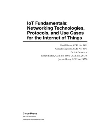
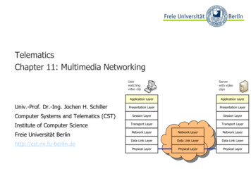
Networking Fundamentals » Volume 6, IP AddressingPage 4S ecti o n 2Below are screen captures showing class B (Figure 4) and class C (Figure 5)sample network addresses. Note the changes in how bits are shown inthe Subnet Bit Mask sections.When IP networking first began, the standard format for any IP addresswas to specify the network number in the first octet and the remainingthree octets were called the rest. Only a few governmental and educationalnetworks that had any ability to access the Internet, then called theARPANET (Advanced Research Projects Agency Network). ARPANETbegan using packet switching protocols like X.25 and switched over toTCP/IP January 1, 1983. It soon became apparent that the 254 networkaddresses that the original design allowed would be quickly exhausted.RFC 791 was already in the works. This RFC describes in detail severalof the internet protocols and a new form of addressing that extendsthe flexibility of network addressing — Classful IP Addressing. Classfuladdressing allows for the division of what was the rest field to allow forsignificantly more networks. Here is how classful address is defined.Figure 4. Class BIPv4 Classful IP Addressing The most significant bits of the first octet signify the network class If the most significant bit is 0, this is a class A network and thenext 7 bits represent the network number. The remaining 24 bitsrepresent host addresses. If the first 2 most significant bits are 1 0, this is a class B networkand the remaining 14 bits of the first 2 octets represent the networknumber and the last 2 octets represent host addresses. If the first 3 significant bits are 1 1 0, this is a class C network and theremaining 21 bits of the first 3 octets represent the network and thelast octet represents host addresses. If the first 3 significant bits are 1 1 1, this is a reserved network rangefor future use.Figure 5. Class CThe classful IP addressing system provides about 3.7 billion unique IPaddresses as shown below in Table 3.Table 3.ClassApplicable NetworksNumber ofNetworksNumber ofAddress perNetworkA1.0.0.0 – 126.0.0.012616,777,214 B128.0.0.0 – 191.255.0.016,384 65,534C192.0.1.0 – 223.255.255.02,097,151254This was assumed to allow for plenty of unique IP addresses for theforeseeable future. It didn’t take long for issues to arise with this addressingscheme. These included: Wasted addresses. If a small company needed access to the Interneton 400 devices, a Class C network would be insufficient so thesecompanies were assigned class B networks. This would leave about65 thousand addresses, or 99.4% of the Class B assigned addressesunused. The division of networks and host boundaries was too rigid.Let’s take a look at the Classful Subnet Calculator tab in SolarWindsAdvanced Subnet Calculator (included in Engineer’s Toolset), and seehow some classeful addresses are divided bit-wise into: Complicated Internet routing tables. With no method of aggregatingroutes or dividing the Internet into smaller chunks, Internet routers wouldeventually require over 2 million entries to route to all possible networks. Class indicatorsWhile classful addressing was the basis for IP internetworking, thelimitations became so great that without new methods of controlling IPallocation, the available IP address space would not have lasted into thelate 90’s. It was clear that steps had to be taken to preserve IPv4 addressspace wherever possible. Network bits Host bitsFor these examples, we will use the native subnet masks which are: Class A 255.0.0.0 Class B 255.255.0 0 Class C 255.255.255.0Figure 3.Private IP AddressesTo help alleviate the usage of registered IP addresses for systems thatdid not require direct connection to the Internet or other registered IPnetworks, a set of address was set aside. These addresses can be used forany system that communicates within a private network. Because theseaddresses are never allowed on the Internet, they can be reused by anynumber of private networks. Below (see Table 4) is a table of the privateIP address ranges as described by RFC 1918.Table 4.Looking at the Subnet Bit Mask section (Figure 3) we can see theassignment of bits for the class indicator, network and host. The first octetof this IP address (21) is represented in bit format as 0010101. Seeing thatthe most significant bit is a 0, this bit is the class indicator and this is aclass A network. The class indicator bits are marked in red in AdvancedSubnet Calculator. The next seven bits are blue n’s indicating these arenetwork bits and the host bits are marked as green h’s.Address SpaceNetworks10.0.0.0 – 10.255.255.2551 Class A Network172.13.0.0 – 172.31.255.25516 Class B Networks192.168.0.0 – 192.168.255.255265 Class C NetworksPrivate IP addressing has undoubtedly saved the unnecessary waste ofassigning registered addresses to every IP enabled device, and has alsohelped reducing hijacking (unauthorized use) of registered address space.There is one severe limitation to private IP addressing — the IP privateaddresses used make an island network, unable to communicate with outsidenetworks. This is where Network Address Translation (NAT) comes in.
Networking Fundamentals » Volume 6, IP AddressingNetwork Address Translation (NAT)Private IP addresses do not help very much if systems with private addressescannot access services outside the private network space. Here is howNAT works to solve this issue (see Figure 6).Figure 6.Page 5Table 5.Inside AddressInside PortRegisteredAddressOutside 12151215.11.12.355351One issue with NAT is the UDP and TCP packets contain header checksumswhich are calculated based upon the TCP/UDP/IP header. If a NAT systemsimply changes an IP address or port number, the checksum will now bein error when recalculated by the end system. Therefore, the NAT/PATsystem must recalculate the checksum fields before forwarding packets.The same applies when the NAT/PAT system reverse-NAT’s the packetsand sends to the original, privately addressed system. A system with the private IP address 10.5.12.33 needs to access aweb server on the Internet with the registered IP address 72.163.4.61. Because private IP addresses like 10.5.12.33. are not allowed on theInternet, this address must be translated to one that is Internet routable. The Internet router connected to the 10 net has NAT enabled and sotranslates the 10.5.12.33 address to a registered IP address from its listof configured, registered addresses, such as 215.11.12.3. The NAT router then makes a request to open the web site at 72.163.4.61from the translated address of 215.11.12.3. The web server returns the web content to the NAT router for deliveryto 215.11.12.3. The NAT router reverse translates the target IP web response to theoriginal IP address of 10.5.12.33.In this example the NAT router only has one translation to keep track of.Typically, NAT routers have from scores to hundreds of translations tomaintain. The NAT router keeps these translations in one of two types: Static translations, used where a private internal system always connectsto the same public system. Dynamic translation, used for allowing private systems to connect tovarious public systems.Dynamic systems allow a relatively small pool of public addresses to be usedfor a large population of users on a private network. When a private useron a dynamically NAT’ed network requests access to a public addressedsystem, the NAT server looks for the next available registered addressin its NAT pool and maps the original private address of the requestor toan available public address. Once the connection to the public device isno longer needed, the NAT router releases the registered address backinto the NAT pool for reuse.A NAT router may multiplex a single registered IP address by translatingthe layer 4 port number as well and the private IP address. This type oftranslation is called Port Address Translation (PAT). Here is a simplified,hypothetical PAT table (see Table 5). Because the registered IP addressis using unique ports for each internal address and port, the 215.11.12.3registered address can be used simultaneously in these multiple PAT devices.The ports used are above the values of INNA controlled ports. This avoidstranslating to INNA well known ports, which may cause protocol errors.
Networking Fundamentals » Volume 6, IP AddressingS ecti o n 3Classless Internet DomainRouting (CIDR) AddressingIn Section 2 — Classful Addressing, we saw that the most significant bits ofthe first octet in an IP address determined the class of that address. Theseare the class indicator bits and all remaining bits in a classful address areeither network or host bits. In CIDR addressing the bits can only representnetwork field bits or host field bits. In classful addressing the networkaddress value could only fall on a byte boundary — in CIDR addressingany number of the most significant bits can represent the network numberand the remaining bits represent host addresses. Because there is nolonger a distinction of network class based on the most significant bits,this system is called classless.Page 6Requesting a Registered CIDR BlockRegional Internet Registries (RIRs) are organizations are responsible formanaging the requests for CIDR blocks from within their individual regions.These RIRs participate together in an entity called the Number ResourceOrganization (NRO). The NRO assists RIRs with the coordination of CIDRblocks. All of the RIRs are assigned their CIDR blocks, (usually in /8 blocks)from Internet Assigned Numbers Authority (IANA), the big daddy ofCIDR assignment. Here is how this all typically works (see Figure 10):Each RIR is responsible for assigning address blocks of the proper sizeto requestors in their region. The RIRs and their respective regions are:Figure 10.The magic behind CIDR is the use of a Variable Length Subnet Mask(VLSM). VLSM allows for the network/host address boundary to occuranywhere in the 32 bit IP address. A network sample address in CIDRnotation is 215.15.62.0/24. The /24 indicates that the first 24 bits arenetwork bits and the remaining bits are host bits. Let’s compare a classful,class C network in Advanced Subnet Calculator with the same networknumber in CIDR notation (see Figures 7 and 8).Figure 7.Classful 215 NetworkFigure 8.CIDR 215.15.62.0/24 Block ARIN — American Registry for Internet Numbers. North America, someCaribbean and Central American nations and Antarctica.Note how all of the leading 24 bits are network bits. Now we’ll move thenetwork bit boundary by changing the CIDR prefix size to 26 bits (/26).Figure 9.CIDR 215.15.62.0/26 BlockNow all of the first 26 bits are networkand 6 bits are left for host addressing(see Figure 9). This flexibility makes itpossible to assign blocks of registeredIP addresses to better fit the actualneed of each requesting organization.Now we’ll take a look at how theserequests are made, and why youwould want to use CIDR subnettingand supernetting. LACNIC — Latin American and Caribbean Registration Authority.Central and South America as well as Caribbean nations. APNIC — Asia-Pacific Network Information Centre. All Asia-Pac nations. AfriNIC — African Network Information Center. All of Africa RIPE NCC — Reseaux IP Europeens Network Coordination Centre.Europe, Central Asia and the Middle East.The RIRs take the /8 blocks assigned to them and break them up intosmaller networks by shifting the CIDR bits. Below (see Figure 11) is a samplefrom the IANA Address Registry taken at the time this paper was written.Figure 11.The left numbers represent abbreviated CIDR blocks. The 099/8 blockis the CIDR network block 99.0.0.0/8. As is, this block is one singlenetwork with 224 host addresses, just like the case of a classful, class Anetwork. The second column lists the RIR the block has been assignedto. Here we can see that 095/8 was assigned to RIPE NCC and 099/8has been assigned to ARIN. 100/8 has not yet been assigned to an RIR,thus IANA is listed as the address authority. The date range listed is therange when addresses from that block were assigned to a RIR and the RIRwas actively working on further assigning. The ALLOCATED note doesnot mean that all of the addresses in this block are used, it just indicatesthat the IANA has allocated the block to an RIR.
Networking Fundamen
Let’s take a look at the Classful Subnet Calculator tab in SolarWinds Advanced Subnet Calculator (included in Engineer’s Toolset), and see how some classeful addresses are divided bit-wise into: Class indicators Network bits Host bits For these examples, we will use