Transcription
INSTALLATIONMANUALPin Foundations, Inc.Gig Harbor, WashingtonToll Free: 866-255-9478 / Main Office: 253-858-8809www.pinfoundations.com or www.diamondpiers.com
2020 by Pin Foundations, Inc. All rights reserved. DOC0001/0.2020Diamond Pier Foundation Systems are covered by U.S. Patents 5,039,256; 6,910,832; 7,326,003; andpatents pending.Diamond Pier is a U.S. registered trademark of Pin Foundations, Inc.The latest version of this Installation Manual is available on our website, www.diamondpiers.com, or bycalling us at 866-255-9478 (Toll Free) or 253-858-8809 (Main Office).Other documents and publications referenced in this manual are listed below and available atwww.diamondpiers.com.National Evaluations“Diamond Pier DP-50 & DP-75 for Bearing Pin Piers,” ICC-ES Evaluation Report No. ESR-1895, 2017.State Evaluations“Diamond Pier DP-50 & DP-75 Precast Concrete Pier Foundation Assembly,” Wisconsin BuildingProduct Evaluation, Code Approval No. 201612-O (Replaces No. 201008-O), November 22, 2016.Observational Evidence“Diamond Pier National Performance Submittals,” 2005.“Diamond Pier Frost Performance Report, Zone II, Minnesota Soils,” 2010. “Diamond PierObservational Evidence, Forest Lake, Minnesota,” May 2011.PFI Frost Performance Study 2109Building Code Compliance Documents“Code Compliance Information for Diamond Pier Foundations in the State of Michigan,” PinFoundations, Inc., Revised January 2018.“Code Compliance Information for Diamond Pier Foundations in the State of Minnesota,” PinFoundations, Inc., Revised January 2018.
CONTENTSINTRODUCTION . 4Soils . 4Pin Pile Technology . 4Diamond Pier Foundation System . 4CONDITIONS AND USES . 5Normal Soil Conditions . 5Supporting Soils . 5Residential Diamond Pier Load Chart. 6Use and Applications . 7Frost Heave . 7Heave Resistance . 7INSTALLATION INSTRUCTIONS . 8Prior to Installation . 8Inspect for Underground Obstacles . 8Locate Buried Utilities. 8Check Your Layout . 9Assemble Tools and Supplies . 10Inspect and Prepare Diamond Pier Components . 10Install Inspection Plugs in Pins. 11Installation . 11Identify and Mark Location . 11Set the Concrete Head . 11Drive in the Pins . 12Encountering Obstructions . 13Removing Pins . 13Place Pin Caps on Pins . 14Register Your Product Warranty . 14AUXILIARY PARTS AND EQUIPMENT . 15Post/Beam Brackets . 15Breaker Hammers and Driving Bits . 15FIELD INSPECTION . 16Pin Length Inspection . 16Pin Specifications . 16Concrete Head Integrity . 16Allowable Capacity . 17SPECIFICATIONS . 18References/Standards . 18Delivery/Storage and Handling . 18Pins . 18Connections/Posts/Beams . 18Site . 18Installation . 18TROUBLESHOOTING . 19Diamond Pier Installation Manual3
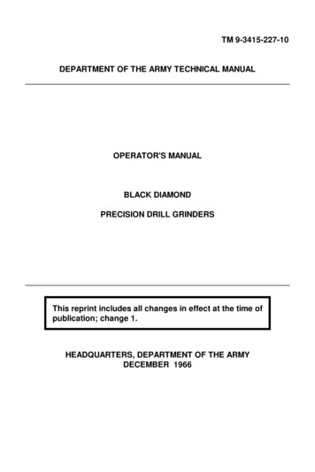
INTRODUCTIONSoilsPin Foundations, Inc. (PFI) has been designing and manufacturing foundations for over 25 years. Onething has always driven our thinking—the Earth is the actual foundation, and soils, in their naturalundisturbed state, have the strength and structure to do the job.Man-made foundations have two basic functions: to transfer loads properly into the Earth’s soil structureand to provide a connection to the built structure above. There are two general types of man-madefoundations: deep vertical pilings (banged in) and shallow spread footings (dug in and buried). Pilingskeep the Earth’s existing soil strength and structure intact, and are easy to install if they do not need togo too deep. Footings spread loads more widely, but the digging breaks apart the soil, weakening it andblocking or exaggerating water flow.Pin Pile TechnologyPin pile technology combines the best features of both types of man-made foundations. By groupingshort stiff piles (bearing pins), which can easily be driven into intact penetrable soils, and setting them atangles to work more like a shallow footing, a sound foundation can be constructed that requires noexcavation. The pin pile group simulates nature’s design, resembling the roots of a tree providingbearing, uplift, and lateral capacity. In recent decades, grouped pin piling has become a reliable technology for complex, heavy-duty commercial applications, performing a superior job of transferring loadsto intact undisturbed soils.Diamond Pier Foundation SystemPFI’s innovation is to bring pin pile technology into common use with a superior connector—the Diamond Pierconcrete head. This high-strength, precast component isa driving guide, a pin piling lock, and a structural connection all in one. As a driving guide, the head maintainsthe pin angles so that their capacity is definable andconsistent. As a lock, the head is designed to increaseits grip on the pin cluster when loaded up, down, or sideways—getting stronger and tighter as loads increase.And as a connection, an embedded anchor bolt andprecast, post-matching shape make it a simple andproportional complement to its supported structure.This concrete head combined with the bearing pin groupFigure 1. Diamond Pierforms the Diamond Pier system—a hybrid of familiarFoundationComponentsconcrete and steel materials. This system provides asolid, stable, economical foundation that both capturesand preserves the supporting strength and natural functions of the Earth’s soil it's engaged in and, inturn, solidly and simply connects to and protects the permanent structures above.This manual provides information and instructions for installing Diamond Pier foundations in residentialapplications in Normal Soil Conditions (see next section).Diamond Pier Installation Manual4
CONDITIONS AND USESNormal Soil ConditionsDiamond Pier foundations sold through retail outlets are designed for projects that are founded in normalsound soils. Normal soils are typical in most residential neighborhoods throughout the United States andare defined in the International Residential Code (IRC) Table R401.4.1. Presumptive Load-BearingValues of Foundation Materials.For residential applications, the two most common prescriptive bearing soil types relied upon in the IRCtable, and in most local codes, are 2000 psf sands/gravels and 1500 psf silts/clays. Diamond Pierfoundations sold through retail outlets must be founded in soils with a minimum 1500 psf bearingstrength. Supporting soils that do not meet the presumptive bearing strength defined in the applicablecode for your area will not provide expected foundation capacity, and their bearing capacity may need tobe determined by a soils investigation. Ask your local code official for soil information regarding yoursite. Additional soils information may also be available at the U.S. Geological Soils Survey websitemanaged by the U.S. Department of Agriculture—see http://websoilsurvey.sc.egov.usda.gov/.Supporting SoilsSome soils may not be appropriate for supporting Diamond Pier foundations. Some examples includesoils that are weaker than 1500 psf, soils that are highly expansive, shifting or sliding soils, soils onslopes greater than 2:1 (27 degrees), contaminated soils, or soils where traditional concrete piers,accepted by local codes, are unable to provide adequate bearing to support the loads of the project or toprotect the structure from the negative effects of frost heave. Where unsound soils exist, a registereddesign professional may be required to review the project.Soils can also be weakened when they retain standing water or are improperly drained, and in certaintypes of soil this can also cause heave problems. A site depression with standing water or the potentialfor water to pond, pool, or saturate the soil may be an indication that the soil is not sound. Downspoutsthat discharge at or near a foundation may also cause soil problems, and setting a Diamond Pierfoundation adjacent to any water body should be considered carefully. Depending on the variablesinvolved, soils at the edge of or within lakes, ponds, rivers, streams, or tidal zones may be considerablyweaker (as much as 40% or more) than dry or well-drained soils. Soils adjacent to existing foundationsmay also have been improperly or loosely backfilled, which may also cause poor drainage or poor soilconditions. Be sure to inform your project designer if any of these conditions exist.Please contact PFI if you have any questions regarding your project or soil conditions, and/or the properuse of the Diamond Pier product or “Residential Diamond Pier Load Chart,” provided in Table 1.WARNING: You must check for underground utilities and follow the instructionsdescribed under “Locate Buried Utilities” (page 8) before Diamond Pierfoundations can be installed.Diamond Pier Installation Manual5
Residential Diamond Pier Load ChartTable 1. Residential Diamond Pier Load ChartIAS-Accredited Third-Party Bearing, Uplift, and Lateral Field Tests2Minimum 1500 psfSilts/Clays (CL, ML, MH, CH)3Model PinNo.LengthBearing LoadCapacityUplift LoadCapacityLateral LoadCapacityDP-50 / 36"2700#1.8 sf18" dia24"600#600#DP-50 / 42"* 3000#2.0 sf19" dia36"* 900#* 600#DP-50 / 50"3300#2.2 sf20" dia48"1200#600#DP-75 / 50"* 3750#2.5 sf21" dia48"* 1400#* 600#DP-75 / 63"4200#2.8 sf22" dia60"1600#600#Uplift LoadCapacityLateral LoadCapacity EquivalentBase Area CylinderComparison FrostZoneEquivalency to Traditional Concrete FootingsMinimum 2000 psfSands/Gravels(SW, SP, SM, SC, GM, GC)3Model PinNo.LengthBearing LoadCapacityDP-50 / 36"3600#1.8 sf18" dia24"600#600#DP-50 / 42"* 4000#2.0 sf19" dia36"* 900#* 600#DP-50 / 50"4400#2.2 sf20" dia48"1200#600#DP-75 / 50"* 5600#2.8 sf22" dia48"* 1400#* 600#DP-75 / 63"6400#3.2 sf24" dia60"1600#600# EquivalentBase Area CylinderComparison FrostZoneEquivalency to Traditional Concrete Footings*Interpolated from field test values.Notes:1. This load chart is intended for simple structures supported by columns, posts, and beams loaded up to, but notexceeding, the stated capacities. It is not intended for structures with asymmetrical, rotational, overturning, ordynamic forces. Intended uses are described in section 2.0 of ICC-ES prescriptive bearing evaluation reportESR-1895. For projects that exceed the capacities or limitations defined herein, or the intended uses describedin ESR-1895, contact PFI for additional information or site-specific capacity evaluation. See also the Use andApplications download at www.diamondpiers.com.2. Capacities shown are tested to a Factor of Safety of 2, and are applicable in properly drained, normal soundsoils only, with minimum soil bearing capacities as indicated. Copies of the field test reports are available fromPFI upon request.3. See IRC Table R401.4.1, “Presumptive Load-Bearing Values of Foundation Materials,” for a full description ofapplicable 1500 psf and 2000 psf soil types. For soils below 1500 psf, or soils with unknown characteristics,additional site and design analysis is required. For soils above 2000 psf, the values in this chart shall apply.4. All capacities use four pins of the specified length per foundation. Pin length includes that portion of the pinembedded within the concrete head. See “Check Your Layout” on page 9 for more information on pin/pier layout andspacing restrictions.5. For professional engineers designing for short-term transient loads, contact PFI for further information.Diamond Pier Installation Manual6
Use and ApplicationsThe intended use for Diamond Pier DP-50 and DP-75 foundations sold through retail stores is to supportsimple residential projects constructed with columns, posts, and beams. The scope of project is definedas decks, covered decks, walkways, stairways, and accessory structures or similar projects that meetthis intent. Project loads are limited to the capacities defined in the “Residential Diamond Pier LoadChart” shown in Table 1. The load chart shows that Diamond Pier foundations provide equal or betterperformance when compared to traditional concrete foundations claimed as equivalent.In the residential load chart, “cylinder comparison” and “frost zone” values are given. These two valuesdefine the size of the traditional concrete pier foundation that a given Diamond Pier foundation isequivalent to in bearing capacity and frost heave resistance. For example, a DP-50 with 50" bearing pinsshows a cylinder comparison of 20" and a frost zone rating of 48". This compares with a traditional 20"diameter, 48" deep poured concrete foundation. For more information, please refer to the Use andApplications document at www.diamondpiers.com.Frost HeaveFrost is not an unusual or unsound soil condition unless the site has a history of locally acceptedconventional foundations failing due to frost heave or freeze/thaw cycling. In frost zones, a properlydrained, sound soil will freeze solid and hold its foundations tight. In heaving areas, water sources, therate of temperature drop, and certain soil grain sizes can combine to cause pressures on foundations inall directions. The most important of these three factors is the presence of water in the soil, and thismakes proper drainage a must—for all types of foundations.Heave ResistanceMost traditional concrete foundations in frost zones rely on depth and gross weight as protectionsagainst frost heave. They use significant volumes of site-poured concrete, which has the potential formany field condition variables and inconsistent mix designs, and their installation requires considerableexcavation, which weakens the existing soil structure, invites water problems, and leaves substantialamounts of soil to be removed from a site.Diamond Pier foundations resist heave pressures and are often used in areas requiring frost protection.Rather than reaching a specific vertical depth or gross weight, Diamond Pier foundations resist heavepressures with their wide-spreading pin pile groups. Embedded in the intact soil structure, the pins areprevented from changing angle under load by the concrete head, creating a stable foundation for bothbearing and uplift forces. Because of the unique design of the Diamond Pier head, the pins are also freeto move along their axes without compromising the position of the head or its lock on the pin cluster.This feature allows the Diamond Pier foundation to absorb soil strains caused by frost heave orexpansive conditions without losing alignment or transferring these strains to the supported structure.When assessing projects in extreme frost areas, be aware of sites where traditional concrete footings—48" to 60" deep—have failed to resist frost heave, requiring larger, deeper concrete piers. Project sitesthat require concrete footings deeper than 60" to resist frost heave exceed the definition of normal soilconditions and the limits of the “Residential Diamond Pier Load Chart.”Diamond Pier Installation Manual7
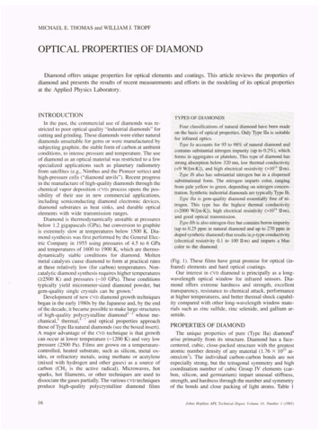
INSTALLATION INSTRUCTIONSThese instructions only cover the installation of Diamond Pier foundations in residential applicationswhere normal soil conditions exist and the “Residential Diamond Pier Load Chart” (Table 1) is referenced (see discussion of “Normal Soil Conditions” on page 5 and “Residential Diamond Pier LoadChart” on page 6).Please also view the “Installation” video provided on our website, www.diamondpiers.com.Prior to InstallationInspect for Underground ObstaclesThe same obstacles that conventional foundation systems encounter, such as rocks, tree roots, underground utility lines, and other buried objects, can also obstruct the Diamond Pier system. Refer to“Encountering Obstructions” (page 13) for instructions on handling buried obstacles. If an obstacle isencountered that cannot be passed using the breaker hammer while driving the pins and not crackingthe concrete pier head in the process, the pins can be removed and the concrete head rotated, allowingthe pins to penetrate the soil in a different location.Locate Buried UtilitiesWARNING: Do not install Diamond Pier foundations before all undergroundutilities have been located, marked, and de-energized.All underground utility lines must be located and properly marked by your local official utility locatingservice, and all privately run lines must also be identified and located by the proper authority. If there areany electrical lines in the area, de-energize the power source prior to installing the Diamond Pierfoundations. Never allow bodily contact with uninsulated portions of the automatic breaker hammer.Wear properly rated rubber-insulated gloves and boots. In addition, if underground utilities are locatedon the site, check with your local utility locating service to confirm required safety zones. You mustensure that the horizontal pin distance for your foundation will have adequate horizontal clearance to bewell outside all safety zones, including the 6" Diamond Pier (DP) safety zone (see Figure 2 and Table 2on next page).Diamond Pier Installation Manual8
Figure 2. Horizontal Pin DistanceAfter installation, horizontal distance of all pins must be well outside all safety zones.Table 2. Horizontal Pin Distance for All Diamond Pier ModelsMeasured from center of pier anchor bolt horizontally to vertical limit of pin end.Horizontal Pin Distance (inches)Pin Length(inches)When Pin Is at 90 degrees(Perpendicular to Limit Plane)When Pin Is at 45 degrees(Shortest Distance to Limit Plane)3620154224175029216338278451361267856Check Your LayoutTo meet the load bearing capacities shown in the “Residential Diamond Pier Load Chart” (Table 1, page6), Diamond Pier foundations must be spaced a minimum of 3 feet apart (from center of pier anchor boltto center of pier anchor bolt). If they are spaced less than 3 feet apart, the bearing capacity must bereduced by 13% for each closer-spaced pier. The piers must also be set back the correct horizontaldistance from existing foundations or other buried obstacles, as shown in Table 2. Tributary loads fromthe supported structure must be properly calculated, and the piers spaced accordingly, so that each pieris supporting only up to its designated allowable loads.Diamond Pier Installation Manual9
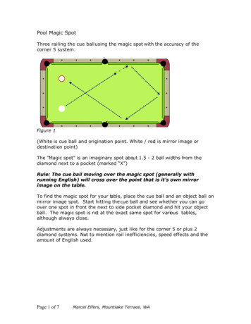
Assemble Tools and SuppliesYou will need to assemble the following tools and gear: Automatic driving hammer with 1-1/8" hex shaft driving bit (see “Breaker Hammers and DrivingBits,” page 15)Square-edge shovelSledgehammerTorpedo levelTape measurePipe wrenchProper protective gear, including safety goggles, ear protection, insulated gloves, protectiveclothing, and bootsWe recommend a minimum two-person crew for installation.Inspect and Prepare Diamond Pier ComponentsInspect your Diamond Pier assemblies (see Figure 3) to ensure that no parts are flawed or have beendamaged in shipping. Do not install a concrete pier if it has a structural crack with a fissure runninginternally into the head (see “Concrete Head Integrity” on page 16). Slight flaking or chipping isacceptable; a concrete head with surface flaking or chipping may be installed.Diamond Pier Foundation Components: Concrete Head (1) with Anchor Bolt Bearing Pins (4) Pin Caps (4) Inspection Plugs (4)Figure 3. Diamond Pier Model DP-75/63" – Concrete Head with Bearing Pinsand Package Containing Pin Caps and Inspection PlugsVerify that you have the correct number of concrete heads with the corresponding number of bearingpins (4 per pier), pin caps (4 per pier), and inspection plugs (4 per pier), and that the anchor nuts threadproperly on the pier anchor bolts. Measure the pin diameter to be sure the proper pins have beensupplied for your pier model. (The DP-50 model has a 1" nominal pin with a 1.315" actual outsidediameter [OD]; DP-75 has a 1-1/4" nominal pin with a 1.67" actual OD.) If the pins do not fit, contact yoursupplier. The inspection plugs are inserted in the bottom of each bearing pin prior to installation to keepsoil from moving up inside the pins as they are driven into the ground. This allows inspectors to slide atape measure down a pin from above as a method to verify its length.Diamond Pier Installation Manual10
Install Inspection Plugs in PinsRemove any dirt and debris from the pins and checkthat they will fit easily into the driving holes in the concrete heads. (If a cut or burr is restricting the fit, try theother end of the pin.)Install the inspection plugs in the ends of the pins thatwill go into the concrete head first. Align the slot in theplug with the interior weld bead and insert (see Figure4). The allowable tolerance in pin wall thickness meansthat some plugs will fit high in the end of the pin, andsome will fit down almost to the plug shoulder. In eithercase, tap the point of the plug with a hammer to seat itfirmly enough in the end of the pin so that it will not dropout as you slide it through the driving holes in the pier.Don’t worry that tapping the end of the plug with thehammer will blunt the point; it is not intended as apiercing or cutting tip, and this will happen anyway asthe plug is driven into the soil. (See “EncounteringObstructions,” page 13, for plug use where buried obstructions may be encountered.)PointShoulderSlotPlug SitsLow inPinPlug SitsHigh inPinThickWall PinThinWall PinFigure 4. Inspection PlugsMust Be Installed in PinsInstallationIdentify and Mark Location1. Identify where you would like the center of the pier anchor bolt to be located.2. Mark the location by using reference points that will easily identify the center location of the piereven after top soil is removed. Tip: Set a string line centered on the anchor bolt approximately12-14" above the ground for a quick reference point and to maintain alignment.Set the Concrete Head1. Dig a tapered square hole the same size and shapeas the bottom half of the concrete head (see Figure 5).This creates a cradle to steady the head for leveling.Soils directly below the head should be left loose.2. Following safe lifting procedures, carefully lift the concrete head and position it in the hole to its midpoint.*Ensure top is level and centered on your alignment.3. Replace some of the removed soils back around thesides of the head at grade, lightly tamping to maintainlevel and alignment during pin driving. (See Notesunder “Drive in the Pins” on page 12.) A few inches ofsmall rounded pea gravel may be used if native soilsare not available.Figure 5. Tapered Hole forConcrete HeadNOTE: The edges of the top of the concrete head do not have to align exactly with the sides of thepost or post bracket as long as the bracket being used is fully supported by the concrete andproviding proper weight distribution.*The concrete head may also be buried for aesthetic considerations, but access to the top of the head needs tobe maintained. Concrete slabs, patios, and other products installed MUST NOT interfere with the Diamond Pierfoundation and the attached post/beam assembly. Expansion joints may be used to protect the foundation.Proper drainage must also be maintained.Diamond Pier Installation Manual11
Drive in the PinsWARNING: Verify locations of any buried utilities before driving pins (see “LocateBuried Utilities,” page 8).1. Slide the ends of the pins with the inspection plugsthrough opposing holes in the concrete head,making sure to support them so their weight doesnot roll the head out of the hole or out of alignment.2. Keeping the pin centered in the driving hole, carefully set each pin 6" to 12" into the soil tapping withthe sledgehammer (gripped just below the hammerhead) until the concrete head is locked into a levelposition (see Figure 6). Impact the pin end squarelyto minimize flaking of the concrete surface ordeformation of the end of the pin (see Note 1).3. With the pin driving bit installed on the automatichammer, and another crew member holding the pin,Figure 6. Setting Pins anddrive in opposing pins alternately in incrementsLeveling Concrete Head(see Note 2). Periodically check for alignment andlevel (a 5-degree tolerance is allowed). Be sure to keep the weight of the auto-hammer fromforcing the pin against the lower half of the driving hole and impacting the concrete head. Theother crew member should hold the pin centered in the driving hole (see Figure 7). This will alsoreduce pin vibration and minimize concrete flaking.NOTE: Do not use the pin driving bit as a hammering tool or hammer against it with thesledgehammer. It is to be used with the automatic hammer only.4. Temporarily drive all pins down to within 6" from thetop of the head; this allows easier removal if anobstruction is encountered (see Note 3).5. Finish driving the pins with the automatic hammer(with pin driving bit), being careful not to damagethe precast concrete head or the upper ends of thepins and leaving approximately 3/4" of the pinprotruding from the top of the concrete.Note 1: Do not attempt to drive the pins all the waydown with just the sledgehammer; this may damage theends of the pins or crack the concrete head.Note 2: Do not drive a pin all the way down at once asthis may cause the
Diamond Pier Foundation Systems are covered by U.S. Patents 5,039,256; 6,910,832; 7,326,003; and patents pending. . Diamond Pier Foundation System . PFI's innovation is to bring pin pile technology into com-mon use with a superior connector—the Diamond Pier concrete head. This high-strength, precast component is