Transcription
08” COMPLIB2008” COMPLIOWNER’S MANUALMAINTENANCEMDX & SDX DRAINS ARE & INSTALLATION GUIDETAN“V G20BTANNSF/ANSI 50“V GSDX HIGH FLOW SAFETY DRAINSUBMERGED SUCTION OUTLETFOR SINGLE OR MULTIPLE DRAIN USEFOR USE ON WALL OR FLOOR2MADE IN USACOMPLIANT WITH THE VIRGINIAGRAEME BAKER ACT 2008.MDX2 & SDX DRAINS ARECOMPLIANT WITH THE VIRGINIAGRAEME BAKER ACT 2008.08” COMPLI“V G20TANBTAN“V GNOTICERead and follow these instructions. Give these instructionsto the facility owner to keep for future reference. Follow allcodes and regulations that apply to the design, installation,08” COMPLI and use of suction outlet fittings.20maintenanceBMDX2 & SDX DRAINS ARECOMPLIANT WITH THE VIRGINIAGRAEME BAKER ACT 2008.08” COMPLIDANGERMDX2 & SDX DRAINS ARECOMPLIANT WITH THE VIRGINIAGRAEME BAKER ACT 2008.B2008” COMPLIPROPER INSTALLATION OF THE SDX RETRO IS ESSENTIAL.MDX QUESTIONS,& SDX DRAINS ARE PLEASE CALL PARAMOUNTIF YOU HAVE ANYCOMPLIANT WITH THE VIRGINIAAT 1.800.621.5886GRAEME BAKER ACT 2008.OR CONTACT YOUR REGIONAL REPRESENTATIVE.PLEASE FOLLOW ALL LOCAL CODES AND POOL SAFETYGUIDELINES.1300634v2/15700-0001TAN“V G20TANBSDX and SDX Retro must be installed in accordance withParamount’s written instruction & maintenance manual, and inconformity with applicable Federal, State, Local and Swimmingpool industry building and safety codes.“V GWARNINGMDX2 & SDX DRAINS ARECOMPLIANT WITH THE VIRGINIAGRAEME BAKER ACT 2008.2US and Foreign patents and patents pending 0REV012616295 East Corporate Place Suite 100 Chandler, AZ 85225Toll Free: 1.800.621.5886 Phone: 480.893.7607 Fax: 480.753.3397Paramount@1Paramount.com www.1Paramount.com
Signal Words and Symbols Used In This ManualThis Owner’s Manual and Installation Guide contains specific precautions and symbols to identify safetyrelated information. You will find DANGER, CAUTION, WARNING and NOTICE symbols which requirespecial attention. Please read them carefully and follow these precautions as indicated! They will explain howto avoid hazards that may endanger you or persons using or maintaining your pool or spa.DANGERWARNINGCAUTIONNOTICEDANGER indicates a hazardous situation which,if not avoided, will result in death or serious injury.WARNING indicates a hazardous situation which,if not avoided, could result in death or serious injury.CAUTION indicates a hazardous situation which,if not avoided, could result in minor or moderate injury.NOTICE is used to address practices not related to physical injury.PLEASE REVIEW THE OWNER’S MANUAL AND INSTALLATION GUIDE IN ITS ENTIRETY ANDHEED ALL SAFETY INFORMATION. Failure to follow these instructions and warnings can result inDEATH OR SERIOUS INJURY.SUCTION ENTRAPMENT HAZARD:DANGERDEATH or SERIOUS INJURY will result if a drain coveror grate is not installed and used correctly. Pool and spa pumps produce high levels of suction and movehigh volumes of water, which can cause death or serious injury ifa person comes in close proximity to pool or spa drains. Keep clear of pool and spa drains to avoid death or serious injury from suction.DANGERDEATH or SERIOUS INJURY will result from hairentanglement or limb entrapment. Keep clear of pool and spa drains. Hair sucked into pool or spa drains will tangle and knottrapping the swimmer underwater. Avoid placing your hairnear a pool or spa drain. Avoid sitting on pool or spa drains because the suctioncan cause severe intestinal damage, evisceration, and/ordisembowelment.For technical assistance call 1.800.621.5886 or contact your regional representative2
DANGERDEATH or SERIOUS INJURY will result from pool or spa draincovers or grates that are improperly installed, missing, clogged,or broken. Inspect pool and spa regularly to insure that drain covers andgrates are properly in place and secured. Ensure that drain covers are not damaged, cracked, broken, loose, clogged, not properly secured, ormissing because these conditions increase the chance of death or serious injury from entrapment. If a drain cover is discovered damaged, cracked, broken, loose, clogged, not properly secured, ormissing, you should: Close the pool or spa immediately; and, Post a closure notice and keep the pool or spa closed until an appropriate ANSI/APSP -162011 certified drain cover is properly installed.DANGERDEATH or SERIOUS INJURY will result from contact with adamaged, loose, or missing drain cover. Do not allow limbs to contact or be inserted into a drain pipe witha damaged, loose, or missing drain cover. This could result inswelling of the limb and/or trapping a swimmer underwater. Avoid mechanical entrapment of jewelry, swimsuit, hairdecorations, finger, toe, or knuckle in a drain pipe withdamaged, loose, or missing drain cover. This may result intrapping a swimmer underwater. Do not allow body to come into contact with a drain pipe thathas a damaged, loose, or missing drain cover. This may resultin trapping a swimmer underwater.MAINTENANCE INSTRUCTIONS & WARNINGS:WARNINGDEATH or SERIOUS INJURY can result from pool or spa draincovers or grates that are clogged by debris. All pool and spa drain covers may become obstructed by debrisand should be cleaned periodically due to clogging from debris, such as pieces of plastic, hair, fabric, twigs,leaves, seeds, etc. The frequency of periodic cleaning will vary depending on the amount and type of debris introduced into thepool or spa Clogging of the drain cover will increase the suction effect and increase the likelihood of death or seriousinjury from those hazards listed above. A clogged drain can negatively affect the safety of the drain. It is advisable to have a qualified pool or spa professional perform this inspection and debris removal fromthe pool an spa drain covers.For technical assistance call 1.800.621.5886 or contact your regional representative3
HOW SDX WORKS BETTERThe SDX high flow drain system is a dual-drain system designed and tested to safely deliver water to modernhigh flow pumps.Each Drain Addresses All Entrapment HazardsHair Entrapment Avoidance. At the heart of the Patented design is a cover that acts much like sixtyself-regulating drains. This is significant because as some of the ‘little’ drains are covered, excessive suctiondoes not transfer to the remaining openings. When excessive suction is transferred to unblocked openingsin a traditional drain grate, the suction causes hair to enter multiple openings, creating a potential entrapmenthazard if the hair tangles or puffs up inside the drain, making it impossible to pull free.Body Entrapment Avoidance. The same self-regulating openings that protect against hair entrapmenthazards, also provides body entrapment protection. When the self-regulating openings built into the SDXcover are combined with it’s domed, anti-vortex shape, forming a seal with the cover is difficult.Security. The SDX cover is held firmly in place with three recessed security screws which are made fromtop quality 316 Stainless Steel. And behind the SDX cover are at least three more screws to hold the wholeassembly in place, providing multiple layers of anti-entrapment protection.Durability. The SDX cover and support materials are far more durable than ABS, the typical plastic used inswimming pool drain covers. In addition to fading, the Buna in ABS is prone to UV degradation resulting instructural failures which contribute significantly to suction entrapment hazards.Dual-Drain SystemVacuum Breaker Backup. As with any dual-drain system, one drain is intended to be a vacuum breaker forthe other in the unlikely event a swimmer completely blocks one of the SDX drains. If this were to happen, thepump is able to safely draw water from the second drain.Dual-Drain Spacing. Most suction safety codes require dual-drains to be installed three feet apart, pipeto pipe, however some codes require three feet between drain covers. For this reason, Dual SDX piping isspaced three (3) feet, ten (10) inches apart.Vertical Dual-Drain Installation. The purpose of the vertical dual-drain installation is to make it less likelytwo people can approach two drains at once. Effectively, the second drain would be at an individual’s feet.For technical assistance call 1.800.621.5886 or contact your regional representative4
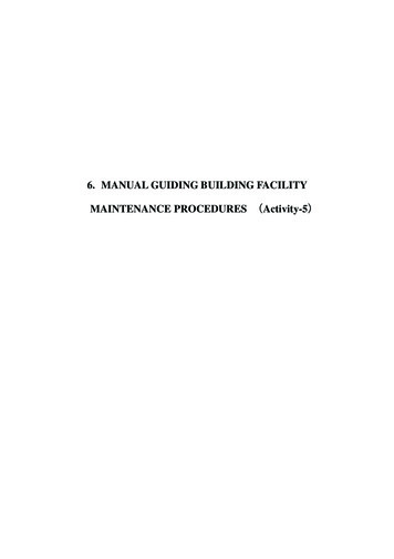
SDX HIGH FLOW SAFETY DRAIN SYSTEM DESIGNSDX is a circulation drain, not intended to remove debris. For this reason it is suggested SDX be installed on wallswhenever possible. SDX is a high flow safety drain system submerged suction outlet suitable for Single or MultipleDrain use on the wall and floor. This is to keep debris and sand from collecting on and around the low velocity SDXcover. Do not locate suction outlets on seating areas or on the backrest of such seating areas.The maximum flow rate for each pair of SDX drains is 200 gpm on the floor --192 gpm on the wall. This flowrating allows for pumps up to 3 hp to operate efficiently. For pumps with higher flow rates or systems withmultiple pumps on a common manifold, additional SDX drains may be added. Do not exceed the maximumallowable flow rate stated on the suction fitting. The velocity at the opening to the SDX drain at the maximumrated flow of 200GPM is 1.485 feet per second. For multiple drain systems where more than two drains areused, the maximum flow rate is calculated per ANSI/APSP-7 Section 4.6 as shown in the following chart.MAXIMUM SYSTEMFLOW FLOORMAXIMUM SYSTEMFLOW WALLMINIMUM FLOW RATING OFEACH COVER %MAXIMUM SYSTEM FLOW RATE*One SDX High Flow Safety Drain200 gpm (756 lpm)192 gpm (726 lpm)100%Two SDX High Flow Safety Drains200 gpm (756 lpm)192 gpm (726 lpm)100%Three SDX High Flow Safety Drains300 gpm (1136 lpm)288 gpm (1090 lpm)66.7%Four SDX High Flow Safety Drains400 gpm (1514 lpm)384 gpm (1456 lpm)50%DESCRIPTION*The addition of an approved SVRS is required when a single SDX is being used.Table derived from ANSI/APSP-7 Section 4.6 Table 1Pipe size. ToSUCTION PIPE SIZEdesign an efficient1½”suction system in2”accordance with2½”national swimming3”pool standards,4”the following pipe*minimum pipe size 1 1/2sizing guidelineshould be followed:MAX RESIDENTIAL GPM5082117181313 (200 Max GPM)MAX PUBLIC GPM376288136234 (200 Max GPM)Flow vs Head Loss9.008.007.006.00Head Loss 08090100110120130140150160170180190200Flow (GPM)For technical assistance call 1.800.621.5886 or contact your regional representative5210220230240250
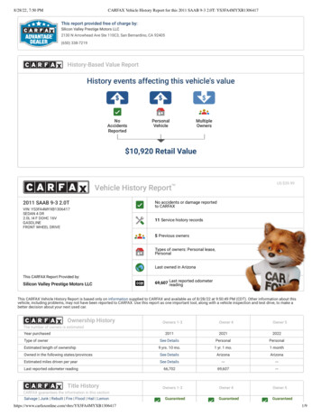
CONCRETE INSTALLATIONConcrete Plumbing “Fig. 2”Fig. 12” Deep (typ)11” (typ)SDX installed in a concrete shell utilizes a small cutoutin the concrete to form the sump which is sometimesmade of plastic or fiberglass. This concrete sumpprovides superior shell strength by eliminating the largehole associated with plastic sumps. The water seal isformed against the suction pipe in the same way a watertight seal is formed with return pipes. The concretecutout is typically eleven (11) inches wide, by two (2)inches deep, with a finger size cutout around the pipe toallow room for a watertight seal. “Fig. 1”Finger SizeCutoutFig. 21. Select the installation location for the dual SDX drains.2. Choose the dual-drain orientation, vertical (preferred)or horizontal.3’10”3. Fabricate the dual-drain pipe tree prior to installation.4. Position at the desired depth before connecting topump suction pipe.Rebar SteelConcrete reinforcing steel should be kept 3” away fromall pipe and fittings.3’10”Concrete Shell SumpFig. 3Form a concrete sump around each suction pipe. “Fig. 3”NOTICEThe pipe size must be appropriate for themaximum anticipated system flow rate per charton page 5. The diameter of branch linesshall be equal and shall not be less than the pipediameter marked on the cover.Concrete Shell Preparation (Fig. 4)Fig. 4Prior to installing the interior finish, cut each SDX riserpipe approximately 1” behind the concrete shell’ssurface.Note: Suction Safety Standards require that maindrain grates used to cover concrete sumps, musthave the suction pipe cut at least 1 ½ times the pipediameter behind the drain cover. This is to allow roomfor even water flow through all drain cover holes. Thisis not necessary with the SDX drain because thePatented design provides uniform suction regardlessof pipe location. However, if the pipe is too close tothe surface, it may restrict water flow to the pump,reducing hydraulic efficiency, but this does not pose asuction safety hazard.For technical assistance call 1.800.621.5886 or contact your regional representative61” Deep (typ)
Concrete Ring Installation (Fig. 5)Fig. 51. Apply interior finishing material.2. Position the SDX Concrete Ring with the semicircle tab located at the top and then press thering into finishing material.3. Trowel the finishing material around outside andinside of the SDX Concrete Ring.3” Min (typ)4. Form a watertight seal around the suction pipe.5. Wipe clean any finishing material that remains onthe SDX Concrete Ring’s top edge and mountingsurface.Concrete Cover Assembly (Fig. 6)Fig. 61. Align the SDX Concrete Support with the alignmenttab located on the SDX Concrete Ring.2. Install three (3) machine screws through the SDXConcrete Support. Secure the screws without overtightening.3. Align the SDX Cover with the SDX Support holes.4. Install three (3) security screws through the SDXcover. Secure the screws without over tightening.Completely hand tighten screws. Do not usepower tools.For technical assistance call 1.800.621.5886 or contact your regional representative7
VINYL INSTALLATION 1. Select the installation location for the dual SDX drains. (Additional SDX drains may be used.)2. Choose the dual-drain orientation, vertical or horizontal. “Fig. 2” pg. 63. For Steel Wall: Make two 4 ½” holes 46” apart using a Greenlee Standard Round Knockout Punch(Greenlee.com - Cat. No. 742BB / UPC No. 19978)Fig. 7 For Plastic Wall:UP ArrowCut two 4 ½” holes 46” apart using a 4 ½” hole saw. For Concrete Wall:Embed two SDX Bulkhead fittings 46” apart.Protect vinyl liner mounting surface from concreteand align the back of the flange with the interiorsurface to allow room for rolled foam around thefitting.1. Install the SDX Bulkhead Fittings with the “UP”arrow located at the top. (Fig. 7)Vinyl Linera. D iscard the solid gasket used for fiberglassshells.Fig. 8b. Mount the SDX bulkhead fittings in the wallwith the UP arrows at the top.c. Secure with the SDX nut. (Not needed forconcrete walls.2. Connect the suction piping. (Fig. 8)Vinyl Cover Assembly (Fig. 9)1. Prior to installing the Vinyl Liner, apply adhesive tothe non-ribbed side of the two notched gaskets.Fig. 92. Align the gaskets with the alignment tabs andscrew holes, then press the gaskets onto theBulkhead Fitting and the Bulkhead Support.Vinyl LinerShell3. After installing the Vinyl Liner, align the SDXVinyl/Fiberglass Support with the alignment tablocated at the top of the SDX Bulkhead Fitting.(Fig. 10)4. Install five(5) self-tapping screws (Fig. 11)through the SDX Bulkhead Support with theT25 Security Screw Driver (Fig. 12). Secure thescrews without over tightening.Notched Gaskets(Fits One-Way Only)Fig. 105. Cut the Vinyl Liner out of the center of the SDXBulkhead Supports to expose the suction piping.6. Align the SDX Cover with the SDX Supportholes.7. Install three(3) security screws through the SDXcover. Secure the screws without over tightening.Completely hand tighten screws. Do not usepower tools.For technical assistance call 1.800.621.5886 or contact your regional representative8Fig. 11Fig. 12
FIBERGLASS INSTALLATIONFig. 131. Select the installation location for the dual SDXdrains. (Additional SDX drains may be used.)UP Arrow2. Choose the dual-drain orientation, vertical orhorizontal. “Fig. 2” pg. 63. For Fiberglass Wall: Cut two 4 ½” holes 46”apart using a 4 ½” hole saw.4. Install the SDX Bulkhead Fittings with the “UP”arrow located at the top.Solid GasketFor Fiberglass Shells: (Fig. 13)Fiberglass Shella. P lace the solid Gasket with the smooth sideagainst the Bulkhead Fitting flange. (Siliconeadhesive may be substituted for the Gasket ifpreferred.)Fig. 14b. Mount the SDX Bulkhead Fittings in the holewith the UP arrow at the top of each fitting.c. Secure with the SDX Nut.5. Connect the suction piping. (Fig. 14)Fiberglass Cover Assembly (Fig. 15)1. Prior to installing the support, apply adhesive tothe non-ribbed side of the two notched gaskets.FiberglassShellFig. 152. Align the gaskets with the alignment tabs andscrew holes, then press the gaskets onto theBulkhead Fitting and the Bulkhead Support.3. Align the SDX Vinyl/Fiberglass support withthe alignment tab located at the top of the SDXBulkhead Fitting. (Fig. 16)4. Install five (5) self-tapping screws (Fig. 17)through the SDX Bulkhead Support with theT25 Security Screw Driver (Fig. 18). Securethe screws without over tightening.SolidGasket5. Align the SDX Cover with the SDX Supportholes.6. Install three(3) security screws through theSDX cover. Secure the screws without overtightening.Fig. 16Completely hand tighten screws. Do not usepower tools.For technical assistance call 1.800.621.5886 or contact your regional representative9Fig. 17Fig. 18
SDX WINTERIZATION PROCEDUREVertical InstallationHorizontal Installation1. R emove grate from upper SDX and install blowthrough plug and blow line until air comes fromlower grate.1. Install blow through plug in pump and blow line toachieve airlock to SDX.This may not be the only means to winterize and maynot be the best option in all environments. It is up to theservice professional to provide adequate winterization.2. Install blow through plug in pump and blow line toachieve airlock to lower SDX.Winterization anti-freeze is to be used as necessaryor when required.For technical assistance call 1.800.621.5886 or contact your regional representative10
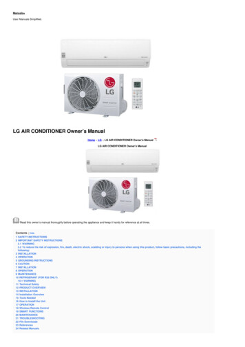
SDX CONCRETE PART NUMBERSReplace within 05 installed years4166523ItemPart NumberDescription1005-252-2084-XXSDX Cover w/ Screws Concrete2005-252-2066-00SDX Support Concrete3005-252-2050-00SDX Ring Concrete4005-252-0828-00Screw: 10 X 7/8 TORX W/PIN SS B (12 pcs)5005-252-0864-00Screw: 10-32 x 1/2 PHIL FLT HD machine (12 pcs)6*005-252-0895-00T25 Security ScrewdriverXX Color Code* Not Part of SDXPROPER INSTALLATION OF THE SDX IS ESSENTIAL. PLEASE FOLLOW ALL LOCAL CODES AND POOL SAFETY GUIDELINES.NOTICESDX and SDX Retro must be installed in accordance withParamount’s written instruction manual and in conformity withapplicable Federal, State, Local and Swimming pool industrybuilding and safety codes.For technical assistance call 1.800.621.5886 or contact your regional representative11
SDX VINYL/FIBERGLASS PART NUMBERSReplace within 05 installed years8291010314567ItemPart NumberDescription1004-182-2212-XXSDX High Flow Safety Drain- Vinyl/Fiberglass (2pc)2005-252-2086-XXSDX Cover w/ Screws Vinyl/Fiberglass3005-252-2068-00SDX Support Vinyl/Fiberglass4005-252-0072-00SDX Gasket Vinyl/Fiberglass5005-252-2035-00SDX Bulkhead Vinyl/Fiberglass 2 1/2”/3”6005-252-0074-00SDX Bulkhead Gasket Fiberglass7005-252-2090-00SDX Bulkhead Nut8005-252-0821-00Screw: 10 X 1¼ TORX W/PIN SS B (12 pcs)9005-252-0816-00Screw: 12-14 x 1” B (12 pcs)10*005-252-0895-00T25 Security ScrewdriverXX Color Code* Not Part of SDXPROPER INSTALLATION OF THE SDX IS ESSENTIAL. PLEASE FOLLOW ALL LOCAL CODES AND POOL SAFETY GUIDELINES.NOTICESDX and SDX Retro must be installed in accordance withParamount’s written instruction manual and in conformity withapplicable Federal, State, Local and Swimming pool industrybuilding and safety codes.For technical assistance call 1.800.621.5886 or contact your regional representative12
SDX is a circulation drain, not intended to remove debris. For this reason it is suggested SDX be installed on walls whenever possible. SDX is a high flow safety drain system submerged suction outlet suitable for Single or Multiple Drain use on the wall and floor. This is to keep debris and sand from collecting on and around the low velocity SDX