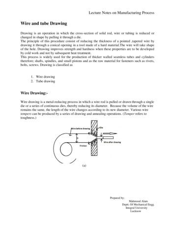
Transcription
Solid Freeform Fabrication 2018: Proceedings of the 29th Annual InternationalSolid Freeform Fabrication Symposium – An Additive Manufacturing ConferenceIMMISCIBLE-INTERFACE ASSISTED DIRECT METAL DRAWINGLi He1,2, Fan Fei1,2, Wenbo Wang1,2, Xuan Song1,2*1Department of Industrial and Systems Engineering, University of Iowa, Iowa City, IA52242, USA2 Center for Computer Aided Design, University of Iowa, Iowa City, IA 52242, USAAbstractState-of-the-art metal additive manufacturing (AM) techniques construct a threedimensional (3D) structure through sintering or melting dry metal powders in a layer-by-layerfashion, which consequently results in some typical manufacturing defects in the final structure,such as residual stress and highly-orientated microstructures. To overcome these defects, wepresent a new low-cost metal AM process, named Immiscible-interface assisted Direct MetalDrawing (II-DMD), which fabricates self-supported and isotropic 3D metal structures bycontinuously extruding a metal colloidal suspension within a second immiscible matrix colloidalsuspension. The shape of the metal colloidal suspension is stabilized due to the presence of animmiscible interface between the two colloidal suspension systems. Dense metal structures can beachieved via post-consolidation of the self-stabilized metal-matrix systems, including liquid-phasedrying and metal-phase sintering. In this article, the immiscible-interface-assisted self-stabilizationmechanism is studied. The post-consolidation processes are discussed. Several test cases werefabricated and characterized.Keywords: immiscible interface, direct metal drawing, colloidal suspension, selfstabilization, heat treatment1. IntroductionTraditional metal additive manufacturing (AM) processes [1] build a three-dimensional(3D) metallic structure through selectively sintering or melting dry metal powders in a layer-bylayer manner using a high-energy beam. The layerwise fabrication method used in those processesresults in many typical manufacturing defects in final structures, such as the staircase effect,residual stress and highly-orientated microstructures. Specifically, the staircases can reduce thesurface finish and introduce stress concentration; residual stress and highly-orientatedmicrostructures caused by the localized high-temperature heating [2, 3] reduce mechanicalproperties of final objects. In addition to these drawbacks, fabrication costs of existing metal AMprocesses are substantially high, due to required high-energy sources, which limit broaderapplication in industry.In this paper, we report a new AM process for fabricating metallic structures ( in particularlattice structures), i.e., immiscible-interface assisted direct metal drawing (II-DMD), which offersthe potential to mitigate the inherent defects associated with layerwise fabrication approaches. Inthis new process, a metal-powder-based suspension is first deposited continuously in 3D space*Corresponding author.2184
within a secondary matrix suspension and then uniformly densified through heat treatment. Bytailoring the two colloidal systems, a suitable immiscible interface can be established between themetal-powder suspension and the secondary matrix suspension, which consequently enables theself-stabilization of the deposited 3D geometry. Similar fabrication techniques [4-12] have beenused to create microvascular networks[12], soft sensors[10], robots[11], and other 3D structures,which are however still limited to polymer materials (e.g. hydrogel) and have not yet beenattempted to build metal structures. The paper is organized as follows. Section 2 describes startingmaterials used in the II-DMD process; section 3 introduces a fabrication system; section 4discusses a mathematic model for the nozzle extrusion of the II-DMD process; section 5demonstrates several test cases and their properties; conclusions and future work are discussed insection 6.2. Starting materialsIn this research, bronze powders are used as a model material to study the II-DMD process.Aluminum oxide is selected to form a secondary matrix suspension due to its high sinteringtemperature ( 1300oC). Bronze-powder-based suspensions are prepared by mixing as-receivedbronze powders (10% Tin, 90% Copper and 0.07% Phosphor, Mesh: 325, Chemical Store Inc.Clifton, NJ, USA) with silicone oil at a specific concentration in a magnetic stirrer for 15 minutes.The resulting bronze-powder suspension needs to exhibit a shear-thinning behavior with yieldstress to achieve controllable extrusion through a pressurized dispenser. Moreover, the shearelastic modulus and yield stress of the achieved bronze-powder suspension should be an order ofmagnitude larger than those of the used secondary matrix suspension to ensure that the suspensionmaintains its shape after it exits the nozzle [13]. A secondary matrix colloidal suspension isprepared by mixing alumina powder (GE6, Baikowski, Charlotte, USA) with deionized water at aspecific concentration in a magnetic stirrer for 15 minutes. Similarly, the achieved matrixsuspension should exhibit a shear-thinning behavior with suitable yield stress to support theextruded bronze-powder suspensions [14]. Additionally, the matrix suspension needs to bethixotropic such that crevices generated by nozzle movement can be immediately closed througha time-dependent backflow.Silicon oil and water are employed as the dispersion medium of metal suspensions andsecondary matrix suspensions respectively to introduce an immiscible interface [15, 16] betweenbronze particles and alumina particles, which is required to achieve the self-stabilization of adeposited 3D shape. More details are discussed in section 3.3. Process DesignA schematic representation of the II-DMD process is shown in Figure 1. A pressurizeddispensing syringe is mounted on a three degrees of freedom (DoF) gantry system. The syringe isloaded with a bronze-powder suspension and is controlled to continuously dispense the suspensionwithin an alumina matrix suspension in a crucible, as depicted in Figure 1a.1. As the bronzepowder suspension is deposited, an immiscible water-oil interface is established between thebronze and alumina particles, which locks the bronze and alumina particles in position andmaintain the 3D shape of the deposited bronze-powder suspension, as shown in Figure 1a.2.2185
Rheological properties of each suspension have been carefully tailored to avoid deformation of thedeposited 3D shape during the fabrication (e.g., fragments, bead up, diffusion, or sedimentation).After a bronze-powder suspension with the desired geometry is achieved, the crucible isheated in an oven to dry the bronze-powder and alumina-matrix suspensions. The drying scheduleis given in Figure 1b. Through this step, a dry bronze-powder compact with the desired geometryis formed, surrounded by a nearly dry alumina powder bed (refer to Figure 1a.3). The aluminapowder bed still contains a small amount of silicon oil that diffused from the bronze-powdersuspension during drying. After that, both the bronze-powder compact and the alumina powderbed are heated together in an argon furnace. The heating temperature schedule is given in Figure1c. Since the used temperature (i.e., 950 ºC) is much lower than the sintering temperature ofalumina powder (e.g., 1400 ºC), only bronze particles are sintered/melted, with the alumina matrixpowder remaining loose. In addition, during the high temperature sintering, the residual siliconeoil in the alumina powder bed is also decomposed. Finally, the alumina matrix powder is removedand recycled for future use, leaving the sintered bronze body as the final product.Figure 1. (a) Schematic diagram of II-DMD; (b) temperature schedule for drying; (c)temperature schedule for sintering.4. Process ModelingThe required solid loadings of bronze-powder suspensions and alumina matrix suspensionsin the II-DMD process were experimentally determined as 94wt% and 40wt%, respectively, whichyield the optimal stability and printability during the process. These materials were used to studythe relationship between extrusion pressures, printing speed and extruded filament size (with afixed nozzle size of 20 Gauge). Figure 2 shows the experimental results and fitting models.2186
As seen in Figure 2a, the achieved metal filament size in an alumina powder bed afterdrying is proportional to the applied extrusion pressure. In contrast, the achieved metal filamentsize is inversely proportional to the square root of printing speed, as shown in Figure 2b. Based onthe experimental results, bronze filament sizes achieved through a 20 Gauge nozzle can beexpressed as the following equation:𝑦𝑦 250 2 𝑝𝑝 𝑣𝑣 0.5(1)In which: y is the filament size (unit: µm); p is the extrusion pressure (unit: psi); and v is the nozzle printing speed (unit: mm/s).(a)(b)Figure 2. Effects of (a) extrusion pressure and (b) printing speed on extruded filament size.5. Test CasesIn this section, several test cases were fabricated to showcase the presented II-DMDprocess. Figure 3a shows a bronze lattice structure, which can be used as structural frames of microrobots. Figure 3b shows a stent structure, which can be applied to prop up a pathological changedblood vessel in the human body if shape memory alloy powder is used.To further demonstrate the capability of the II-DMD process, two cone springs withdifferent sizes were printed and shown in Figure 3c. An optical microscope image of the externalsurface of the springs is shown in Figure 3d. The rough surface finish is mainly caused by a largebronze particle size used in the process. SEM images of the spring specimens are shown in Figure3e and 3f. It can be seen that small pores with diameters around 10 to 40 µm exist in the crosssection, which may be caused by inappropriate selection of bronze particle size and dryingparameters. In Figure 3f, the metal cross section is dense at a macroscopic level, which contributesto relatively good mechanical properties of printed parts. According to a tensile test as shown inFigure 3g, bronze specimens fabricated by our method have a yield strength of 106 MPa and anultimate strength of 148 MPa.2187
Figure 3. Test cases: (a) a lattice structure, (b) stent structure, (c) cone springs, (d) opticalmicroscope image of springs, (e) and (f) SEM images of printed samples, (g) tensile test of afabricated specimen.6. Conclusion and Future WorkIn this article, we report a new and low-cost metal 3D printing process, in which animmiscible interface and unique rheological behaviors of highly-loaded metal and ceramiccolloidal suspensions are utilized to build complex metal lattice structures. It can potentiallyfabricate numerous metal materials without generating staircase effect and the need of supportstructures, and the microstructures of achieved metal parts can be homogeneous and isotropic.Bronze materials are used as a model material to demonstrate the process, with alumina powder asa matrix material. In the future, problems such as rough surface finish and porosity still need to besolved. Fundamental physics behind the II-DMD process will be studied and more materials willbe tested.References[1]Gu, D., Meiners, W., Wissenbach, K., and Poprawe, R., 2012, "Laser additive manufacturing ofmetallic components: materials, processes and mechanisms," International materials reviews, 57(3), pp.133-164.[2]Strößner, J., Terock, M., and Glatzel, U., 2015, "Mechanical and Microstructural Investigation ofNickel-Based Superalloy IN718 Manufactured by Selective Laser Melting (SLM)," Advanced EngineeringMaterials, 17(8), pp. 1099-1105.2188
[3]Chen, H., Gu, D., Dai, D., Ma, C., and Xia, M., 2017, "Microstructure and composition homogeneity,tensile property, and underlying thermal physical mechanism of selective laser melting tool steel parts,"Materials Science and Engineering: A, 682, pp. 279-289.[4]Bhattacharjee, T., Zehnder, S. M., Rowe, K. G., Jain, S., Nixon, R. M., Sawyer, W. G., and Angelini,T. E., 2015, "Writing in the granular gel medium," Science Advances, 1(8).[5]Esser‐Kahn, A. P., Thakre, P. R., Dong, H., Patrick, J. F., Vlasko‐Vlasov, V. K., Sottos, N. R., Moore,J. S., and White, S. R., 2011, "Three‐Dimensional Microvascular Fiber‐Reinforced Composites," AdvancedMaterials, 23(32), pp. 3654-3658.[6]Grosskopf, A. K., Truby, R. L., Kim, H., Perazzo, A., Lewis, J. A., and Stone, H. A., 2018, "ViscoplasticMatrix Materials for Embedded 3D Printing," ACS Applied Materials & Interfaces.[7]Hanson Shepherd, J. N., Parker, S. T., Shepherd, R. F., Gillette, M. U., Lewis, J. A., and Nuzzo, R. G.,2011, "3D microperiodic hydrogel scaffolds for robust neuronal cultures," Advanced functional materials,21(1), pp. 47-54.[8]Moravej, M., and Mantovani, D., 2011, "Biodegradable metals for cardiovascular stent application:interests and new opportunities," International journal of molecular sciences, 12(7), pp. 4250-4270.[9]Subramanian, V., Fréchet, J. M., Chang, P. C., Huang, D. C., Lee, J. B., Molesa, S. E., Murphy, A. R.,Redinger, D. R., and Volkman, S. K., 2005, "Progress toward development of all-printed RFID tags:materials, processes, and devices," Proceedings of the IEEE, 93(7), pp. 1330-1338.[10]T., M. J., M., V. D., L., T. R., Yiğit, M., B., K. D., J., W. R., and A., L. J., 2014, "Embedded 3D Printingof Strain Sensors within Highly Stretchable Elastomers," Advanced Materials, 26(36), pp. 6307-6312.[11]Wehner, M., Truby, R. L., Fitzgerald, D. J., Mosadegh, B., Whitesides, G. M., Lewis, J. A., and Wood,R. J., 2016, "An integrated design and fabrication strategy for entirely soft, autonomous robots," Nature,536, p. 451.[12]Willie, W., Adam, D., and A., L. J., 2011, "Omnidirectional Printing of 3D Microvascular Networks,"Advanced Materials, 23(24), pp. H178-H183.[13]Muth, J. T., Vogt, D. M., Truby, R. L., Mengüç, Y., Kolesky, D. B., Wood, R. J., and Lewis, J. A., 2014,"Embedded 3D printing of strain sensors within highly stretchable elastomers," Advanced Materials,26(36), pp. 6307-6312.[14]He, L., and Song, X., 2018, "Supportability of a High-Yield-Stress Slurry in a New StereolithographyBased Ceramic Fabrication Process," JOM, 70(3), pp. 407-412.[15]Paunov, V. N., Al-Shehri, H., and Horozov, T. S., 2016, "Attachment of composite porous supraparticles to air–water and oil–water interfaces: theory and experiment," Physical Chemistry ChemicalPhysics, 18(38), pp. 26495-26508.[16]Sharp, E. L., Al-Shehri, H., Horozov, T. S., Stoyanov, S. D., and Paunov, V. N., 2014, "Adsorption ofshape-anisotropic and porous particles at the air–water and the decane–water interface studied by thegel trapping technique," RSC Advances, 4(5), pp. 2205-2213.2189
Keywords: immiscible interface, direct metal drawing, colloidal suspension, self-stabilization, heat treatment 1. Introduction Traditional metal additive manufacturing (AM) processes [1] build a three-dimensional (3D) metallic structure through selectively sintering or melting dry metal powd