Transcription
User Guide
ForeSite SS User Guide RevisionAll trademarks appearing in this document belong to XSENSORTechnology Corporation. XSENSOR Technology Corporation. All rights reserved.The XSENSOR Pressure Imaging System is protected by copyrightlaw. Unauthorized reproduction or redistribution of XSENSORsoftware is prohibited. No part of this document may bereproduced or transmitted in any form without the expresswritten permission of XSENSOR Technology Corporation.ASY-05-00005-021
TABLE OF CONTENTSINTRODUCTIONThe ForeSite SS SystemOverviewIntended UseProduct ComplianceSafety StandardsEmission & Immunity StandardsWarnings & Cautions133344511FORESITE SS HARDWAREForeSite SS Tablet Wireless SystemForeSite SS Tablet SystemDisplay Tablet SpecificationsMaintenanceStorage & TransportCleaningCleanable Sensor Instructions1517212730303233FORESITE SS SOFTWAREIntroductionQuick StartUser Roles & SecurityAdministrative SettingsStandard SettingsClient ManagementPressure ImagingGallery Management373939414145484951APPENDIXESAppendix 1 - TroubleshootingAppendix 2 - The Desktop SystemAppendix 3 - Contact Information55565864 1
IntroductionThe ForeSite SS SystemOverviewIntended UseProduct ComplianceSafety StandardsEmission & Immunity StandardsWarnings & Cautions33344511
The ForeSite SS System: OverviewThank you for purchasing the ForeSite SS Pressure Imaging System!The ForeSite SS sensor is embedded with thousands of sensor cells thatcontinuously measure the level of pressure between two solid objects.For clinical purposes, this may be the level of pressure between awheelchair and a client’s body surface. The sensor connects to a touchscreen tablet that displays live pressure information and statistics ona colour-coded scale. The resulting pressure images may be rotated,captured as snapshots, recorded as a series of frames, and evendisplayed in 3D.ForeSite SS is designed to be intuitive and user-friendly in an effortto help wheelchair seating professionals make more informed clinicaldecisions! The ForeSite SS System: Intended UseWheelchair users are at an increased risk of developing pressure ulcerswhich can form when muscles and soft tissue press against surfacessuch as a chair or a bed. As such, preventative measures must be takenin order to reduce these risks. ForeSite SS provides clinicians withthe tools they need to help their clients reduce the risk of developingpressure ulcers. By utilizing ForeSite SS, clinicians are able to create animage of the relative pressure distribution over a surface. The dynamicpressure images then allow them to evaluate the pressure distribution,and, if necessary, take appropriate measures to enhance the pressuredistribution for that particular surface.ForeSite SS is calibrated at the factory to improve the overall accuracyof the pressure distribution images. However, the system is notintended to replace current best practices for prevention of pressureulcers. It is intended to provide additional monitoring and datacollection while standard monitoring techniques and turn schedules aremaintained.Introduction3
This system is designed in compliance with medical safety standards and isintended for the use of clinicians only. It is not recommended for private useor client use without the assistance of a trained medical professional. Thereare no known contraindications to its use. For any questions or concerns inregards to the safety of this product, do not hesitate to contact XSENSOR(see Appendix 4).Product Compliance: Safety StandardsThe XSENSOR Pressure Imaging System complies with the followingstandards: IEC 60601-1:2005, CSA C22.2 No. 60601-1:2008, ANSI/AAMI ES 60601-1/A2:2010, UL 60601-1:2003 Mode of Operation Class I Medical Equipment Type B Applied Part. Only the sensor(s) touch the patient in normal use.The ForeSite SS is intended for use by healthcare professionals only.ForeSite SS must be installed and used as described in this user manual.4Introduction
Product Compliance:Emission & Immunity StandardsThe ForeSite SS is a class A digital device suitable for business, industrial andcommercial environments. It is not intended for residential use. The ForeSiteSS may cause radio interference or may disrupt the operation of nearbyequipment. Portable and mobile RF communications equipment can alsoaffect ForeSite SS. It may be necessary to take mitigation measures, such asreorienting or relocating the equipment or shielding the location.The ForeSite SS should not be used adjacent to or stacked with otherequipment. If adjacent or stacked operation is necessary, the PressureImaging System should be observed to verify normal operation in theconfiguration in which it will be used.Use of accessories and cables other than those provided by XSENSOR mayresult in increased emissions or decreased immunity.ForeSite SS complies with Part 15 of the FCC Rules. Operation is subject to thefollowing conditions: (1) This device may not cause harmful interference, and(2) This device must accept any interference received, including interferencethat may cause undesired operation.Standards Compliance: EN 60601-1-2:2007 (Ed3.0) Medical Electrical Equipment – Part 1:General Requirements for Safety 2. Collateral Standard: ElectromagneticCompatibility (Non-life-supporting, Group 1, Class A Equipment) FCC 15.107/CISPR 11 (Class A) Conducted Emissions FCC 15.109/CISPR 11 (Class A) Radiated Emissions Industry Canada ICES-003(A)/NMB-3(A) Compliant IEC 61000-3-2:2005 Harmonics Emissions IEC 61000-3-3:2008 Flicker Emissions IEC 61000-4-2:2008 Electrostatic Discharge IEC 61000-4-3:2008 Radiated Susceptibility IEC 61000-4-4:2007 Electrical Fast Transients IEC 61000-4-5:2005 Surge Susceptibility IEC 61000-4-6:2006 Conducted Susceptibility IEC 61000-4-8:2001 Magnetic Susceptibility IEC 61000-4-11:2007 Dips & InterruptsIntroduction5
Guidance and manufacturer’s declaration –electromagnetic emissionsThe ForeSite SS system is intended for use in the electromagneticenvironments specified below. ForeSite SS system users should ensurethat it is used in such an environment.6Emissions TestComplianceElectromagneticEnvironment GuidanceRF emissions CISPR 11Group 1The ForeSite SS systemuses RF energy only forits internal function.Therefore, its RFemissions are very lowand are not likely tocause any interferencein the nearby electronicequipment.RF emissions CISPR 11Class AHarmonic emissionsIEC 61000-3-2Class AVoltage fluctuations/flicker emissionsIEC 61000-3-3CompliesThe ForeSite SS systemis suitable for use in allestablishments otherthan domestic and thosedirectly connected to thepublic lowvoltage powersupply network thatsupplies buildings usedfor domestic purposes.Introduction
Recommended separation distances betweenportable and mobile RF communications equipment and the ForeSite SSThe ForeSite SS is intended for use in an electromagnetic environment in whichradiated RF disturbances are controlled. The customer or the user of the ForeSite SScan help prevent electromagnetic interference by maintaining a minimum distancebetween portable and mobile RF communications equipment (transmitters) and theForeSite SS as recommended below, according to the maximum output power of thecommunications equipment.Rated maximumoutput powerof transmitterWSeparation distance according to frequency of transmitterM150 kHz to 80 MHz80 MHz to 800 MHz800 MHz to 2.5 .693.697.38Introduction7
The equipment is intended for use in the electromagnetic environmentspecified below. The customer or the user of the equipment shouldassure that it is used in such an environment.ImmunitytestIEC 60601test levelCompliancelevelElectromagnetic environment - guidanceConductedRF IEC61000-4-63 Vrms150 kHzto 80 MHz3VPortable and mobile RF communicationsequipment should be used no closer to any partof the equipment including cables, than therecommended separation distance calculatedfrom the equation applicable to the frequencyof the transmitter.RadiatedRF IEC61000-4-33 V/m 80MHz to2,5 GHzRecommended separation distance3 V/mwhere P is the maximum output power ratingof the transmitter in watts (W) according tothe transmitter manufacturer and d is therecommended separation distance in meters(m). Field strengths from fixed RF transmitters,as determined by an electromagnetic sitesurveya should be less than the compliance levelin each frequency rangebInterference may occur in the vicinity of knownRF transmitting devices and equipment markedwith the following symbol:NOTE 1 At 80 MHz and 800 MHz, the higher frequency range applies.NOTE 2 These guidelines may not apply in all situations. Electromagnetic ropagation is affectedby absorption and reflection from structures, objects and people.a) Field strengths from fixed transmitters, such as base stations for radio (cellular/cordless)telephones and land mobile radios, amateur radio, AM and FM radio broadcast and TVbroadcast cannot be predicted theoretically with accuracy. To assess the electromagneticenvironment due to fixed RF transmitters, an electromagnetic site survey should beconsidered. If the measured field strength in the location in which the equipment is usedexceeds the applicable RF compliance level above, the equipment should be observed toverify normal operation. If abnormal performance is observed, additional measures may benecessary, such as re-orienting or relocating the equipmentb) Over the frequency range 150 kHz to 80 MHz, field strengths should be less than 3 V/m.8Introduction
The equipment is intended for use in the electromagnetic environmentspecified below. The customer or the user of the Equipment shouldassure that it is used in such an environment.Immunity testIEC 60601 testlevelCompliance level Electromagneticenvironment –guidanceElectrostaticdischarge (ESD)IEC 61000-4-2 6 kV contact 8 kV air 6 kV contact 8 kV airFloors should bewood, concreteor ceramictile. If floorsare coveredwith syntheticmaterial, therelative humidityshould be atleast 30 %.Electrical fasttransient/burstIEC 61000-4-4 2 kV for powersupply lines 1kV for input/outputlines 2 kV for powersupply lines 1kV for input/output linesMains powerquality should bethat of a typicalcommercialor hospitalenvironment. 1 kV line(s) toline(s) 2 kV line(s) toearthMains powerquality should bethat of a typicalcommercialor hospitalenvironment.Surge IEC 61000- 1 kV line(s) to4-5line(s) 2 kVline(s) to earthIntroduction9
Voltagedips, shortinterruptionsand voltagevariations onpower supplyinput lines IEC61000-4-11UT 230 Vac 5 % UT ( 95 %dip in UT) for 0,5cycle 40 % UT(60 % dip in UT)for 5 cycles 70 %UT (30 % dip inUT) for 25 cycles 5 % UT ( 95 %dip in UT) for 0,5cycle 40 % UT(60 % dip in UT)for 5 cycles 70 %UT (30 % dip inUT) for 25 cycles 5 % UT ( 95 %dip in UT) for5 sec 5 % UT ( 95 %dip in UT) for5 secPower frequency 3 A/m(50 Hz) magneticfieldIEC 61000-4-810Introduction3 A/mMains powerquality should bethat of a typicalcommercialor hospitalenvironment. Ifthe user of theequipmentrequirescontinuedoperation duringpower mainsinterruptions, itis recommendedthat theequipmentbe poweredfrom anuninterruptiblepower supply ora battery.Power frequencymagnetic fieldsshould beat levelscharacteristic ofa typical locationin a typicalcommercial orhospitalenvironment.
! Warnings & CautionsThe ForeSite SS System has been designed and tested in accordance withthe previously mentioned safety standards. To ensure safe use of theproduct, follow all safety and operating instructions in this guide. At theend of the System product life, please contact XSENSOR for safe disposalinstructions (see Appendix 4).1. Warning: Use only approved power supplies (SINPRO part numberHPU32A-105 and Glob Tek part number WR9QA1200MICB-N-M)with the ForeSite SS System. Power supplies specified are part ofthe equipment. Do not position any part of the equipment to keep itfrom disconnecting from the mains, should the need arise.2. Warnings: ForeSite SS should only be configured as indicated in thehardware section of the User Guide. Modification of this equipmentis prohibited.3. Warning: The ForeSite SS Sensor should be cleaned between eachuse. Unplug all product components from the wall outlet beforecleaning. See the Maintenance section of the User Guide forinformation on cleaning.4. Warning: The ForeSite SS System is not intended for long term use.5.Warning: The ForeSite SS System is intended for use by health careprofessionals only.6. Warning: To reduce risk of electric shock, connect the Magtech26-2704 to supply mains with protective earth. Where available,connect the equipment to a receptacle marked “Hospital Only,”“Hospital Grade,” or an equivalent.7.Warning: Always completely disconnect the power cord fromyour chassis whenever you work with the hardware. Do not makeconnections while the power is on. Sensitive electronic componentscan be damaged by sudden power surges.8. Warning: Do not connect any external accessories, includingcomputers, cables, or peripherals, to the ForeSite SS Display Tabletinput/output ports (USB, Ethernet, and HDMI) which is part of awired (USB Sensor Pack) system during client pressure monitoring.If using the ForeSite SS Tablet Wireless System (Wireless SensorPack), please note that the ForeSite SS tablet is no longer medicallycompliant when connected to any external accessory. As such,please ensure the tablet and any accessory equipment are kept atleast 1.83m (6’) away from the subject when connected.Introduction11
9.Warning: Do not use the ForeSite SS System if any of the cablesto and from any of the enclosed units are damaged or frayed. Thisincludes the power supply and Sensor USB cable. Contact XSENSORto replace damaged cables (see Appendix 4 of the User Guide).10. Warning: Do not use the ForeSite SS System if the Sensor pad’scovering material is visibly damaged or punctured. Ensure thatclients making contact with the Sensor do not have sharp objectson their person, and that no sharp objects make contact with theSensor, as it may puncture the Sensor during use. Contact XSENSORfor a replacement Sensor if it becomes damaged; do not attempt torepair with cheap materials such as tape or glue.11. Warning: Do not use the equipment in the presence of a flammableanesthetic mixture with air, oxygen, or nitrous oxide.12. Warning: Do not use the ForeSite SS Sensor to lift the client or tohelp remove the client from a seated position.13. Warning:ForeSite SS Tablet may become hot with extendeduse in a hot environment. Handle with care and avoid contact withhot surfaces. Do not place tablet on any body surface. Place on ahard surface and do not impede airflow.14. Warning: Always lay the Tablet on a flat, sturdy surface when not inuse to prevent damages from falling.15. Warning: Do not allow clients to handle the Tablet or Sensorcables; these should be handled only by registered health careprofessionals.16. W arning: Do not attempt to service this product by yourself, asopening or removing covers may expose you to dangerous voltagepoints or other risks and will void the warranty. Refer all servicingto qualified service personnel.17. Warning: Do not touch the LCD panel surface with sharp or hardobjects.18. Warning: The ForeSite SS Sensor is not intended for direct contactwith the client’s skin and should be covered with a sheet orclothing.19. Warning: The Sensor is not defibrillator-proof.20. Caution: Administrative options and settings must be reviewed andselected by a qualified medical practitioner.12Introduction
21. Caution: Never intentionally expose the Sensor pad to moisturebesides the specified cleaning agents. Refer to the Maintenancesection of the User Guide for more information on cleaning.22. Caution: For the Sensor, labeling and grid marks must face towardsthe client’s body; do not use the flip side of the Sensor against aclient’s body.23. Caution: The ForeSite SS System is designed for indoor use only.24. Caution: For information regarding the safe disposal of the ForeSiteSS Display Tablet or Sensor at the end of product life, contact a localXSENSOR representative or XSENSOR directly (see Appendix 4 of theUser Guide).25. Caution: Only use the cables provided with the ForeSite SS System.26. Caution: Ensure power cords do not trail on the ground, to avoidtripping hazards.27. Caution: Avoid damage to the Display Tablet by never setting orresting another object on it while it is not in use.If any of these warnings or cautions are unclear, do not hesitate to contactXSENSOR immediately for more information (see Appendix 4).Introduction13
NoonDeple
ForeSite SSHardwareNote: For informationon using ForeSite SSDesktop Systems,please see Appendix#2.ForeSite SS Tablet Wireless SystemForeSite SS Tablet SystemDisplay Tablet SpecificationsPower Supply Specifications17212729X4 Lithium-Ion BatterySpecificationsMaintenance29Storage & TransportCleaningCleanable Sensor InstructionsForeSite SS Label Symbols3030323335
16ForeSite SS Hardware
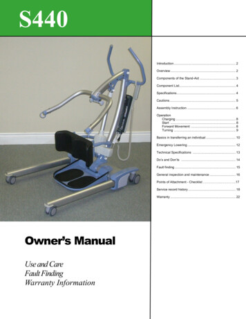
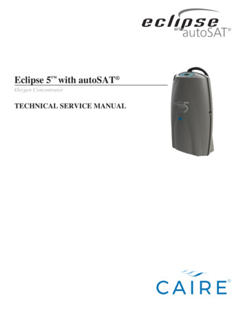
ForeSite SS Tablet Wireless SystemSingle Pad Sensor SystemBAEDCFComponentsA ForeSite SS Tablet (with software installed)B ForeSite SS Tablet power supply (and power cord)C Pressure Imaging Sensor PadD Wireless Sensor Pack with battery (X4)E X4 Power Supply (for recharging)F Documentation USB Flash Drive- ForeSite SS Desktop Software**- ForeSite SS User GuideG ForeSite SS Quick Start Guide (not shown)H ForeSite SS Carry Case (not shown)* See Appendix 2 for the ForeSite SS Desktop System Set-UpWarning: To ensure operator and subject safety and compliance withregulations detailed on Page 5, connect and operate ForeSite SS onlyas described here.ForeSite SS Hardware17
Set-Up Instructions1. Begin by ensuring both the ForeSite SS tablet and the X4 are fullycharged. Recommended charge time to ensure a full charge is 2-3hours for both devices. For the X4, connect the micro-USB on the X4power supply to the micro-USB input on the X4, as shown in Figure1. For the ForeSite SS tablet, connect the tablet power supply andcord to the tablet as shown in Figure 2.Figure 1Figure 2Warning: Use only XSENSOR approved power supplies with ForeSite SS.Do not connect any other USB device or cable to the X4.2. Inspect the sensor pad covering material and cable for signs ofdamage. These include, but are not limited to, tears, punctures,cracked enclosures, and/or exposed wiring. If damage is identified orsuspected, contact XSENSOR for repair (see Appendix #4)Warning: Do not attempt live pressure imaging if the sensor pad isdamaged or soiled. Refer to the Maintenance section of this user guidefor more information on cleaning.3. Connect the X4 to the sensor pad for Wired Set-up, plug the microUSB into the X4 enclosure and the other end into the tablet.4. For wireless setup, connect the X4 to the sensor pad via bluetoothsettings. On the tablet, go to Bluetooth devices and ensureBluetooth is on. Your tablet will search for discoverable Bluetoothdevices. Pair it with the sensor (device will start with WSPK).18ForeSite SS Hardware
Figure 3CLEANABLECLEAN ONLY ASRECOMMENDEDIN USER GUIDEIf the sensor has one of the followingmarkings, it is cleanable as per theCleanable Sensor Instructions sectionof this User Guide.For sensors WITHOUT this label, place sensor in the approvedprotective sleeve provided by XSENSOR before placing on the desiredsurface. Ensure that the protective sleeve separates the portions ofthe sensor pad that may come into direct continuous contact with thesubject. The cabling from the sensor to the sensor pack should existfrom the open end of the sensor protective sleeve.5. Power ON the X4 by pressing the ON/OFF button for at least twoseconds (Figure 4). The power light will glow green.6. Power ON the tablet by pressing the ON/OFF button for at least 3seconds (Figure 5). The power LED indicator on the display panelwill turn blue. See the ForeSite SS Software section of this guide fordetails on using the software.7. The ForeSite SS system is now ready for use. Before the subjectmakes contact with the sensor, ensure that they do not have anysharp objects or protrusions that may puncture/tear the sensor padcovering material.Figure 4Warning: Neither sensor pads norprotective sleeves are intended forcontact with bare skin.Figure 5ForeSite SS Hardware19
Dual Sensor Pad SystemsDual sensor pad systems include all the same components as listedabove for the single pad systems with the exception of: 1 additional Pressure Imaging Sensor Pad 1 additional Wireless Sensor Pack (X4)The dual sensor pad system is set-up the same way as the singlesensor pad system with the exception that it requires you to repeatthe instructions above for charging, connecting and powering ON yoursecond X4.NOTE: Ensure that the power adaptor corresponds to the plug asprovided in your country (see chart). XSENSOR is not responsible fordamages that may sustain if an incorrect power source is used.North entalEuropeanItalianJapaneseSwissIf a different power adaptor is required for your country, please contactXSENSOR for a replacement (see Appendix 4). For medical applications,only use a “Hospital Grade” power cord (or equivalent) to connect thepower supply to receptacles marked “Hospital Grade” or equivalent.20ForeSite SS Hardware
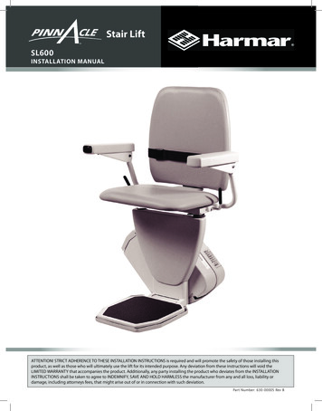
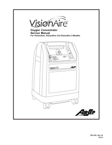
ForeSite SS Tablet SystemSingle Pad Sensor SystemBACEDComponentsABCDEForeSite SS Tablet (with software installed)ForeSite SS Tablet power supply (and power cord)Pressure Imaging Sensor PadSensor Pack (SPK) (with SPK adaptor)Documentation USB Flash Drive- ForeSite SS Desktop Software*- ForeSite SS User GuideF ForeSite SS Quick Start Guide (not shown)G ForeSite SS Carry Case (not shown)* See Appendix 2 for information on ForeSite SS Desktop SystemsSet-Up InstructionsWarning: To ensure operator and subject safety and compliancewith regulations detailed on Page 5, connect and operate ForeSiteSS only as described here.ForeSite SS Hardware21
Figure 11. Begin by ensuring the ForeSite SS tablet is fully charged. Recommendedcharge time to ensure a full charge is 2-3 hours. To charge, connect thetablet power supply and cord to the tablet as shown in Figure 1.Warning: Use only XSENSOR approved power supplies with ForeSite SS.2. Inspect the sensor pad covering material and cable for signs of damage.These include, but are not limited to, tears, punctures, crackedenclosures, and/or exposed wiring. If damage is identified or suspected,contact XSENSOR for repair (see Appendix 4)Warning: Do not attempt live pressure imaging if the sensor pad isdamaged or soiled. Refer to the Maintenance section of this user guidefor more information on cleaning.3. Connect the SPK to the sensor pad cable connection point (aka CONN)as shown in Figure 2. The SPK and CONN are connected correctly whenthe labels on each are both aligned, as shown. The alignment betweenthe two connections is stiff to ensure reliable electrical connectivity. Assuch, press the two together gently but firmly until you hear a “click”.This indicates that you have a secure and reliable connection.4. Connect the SPK adaptor (connected to the SPK) to the tablet USB portas shown in Figure 2.Warning: The SPK adaptor must only be used with the ForeSite SSTablet. Do not connect to any other USB device.5. Place the sensor pad on the desired supporting surface, such as a chairor a bed. Ensure that the sensor’s grid is facing towards the subjectapplying the pressure.22ForeSite SS Hardware
Figure 2If the sensor has one of the followingmarkings, it is cleanable as per theCleanable Sensor Instructions sectionof this User Guide.CLEANABLECLEAN ONLY ASRECOMMENDEDIN USER GUIDEFor sensors WITHOUT this label, place sensor in the approvedprotective sleeve provided by XSENSOR before placing on the desiredsurface. Ensure that the protective sleeve separates the portions ofthe sensor pad that may come into direct continuous contact with thesubject. The cabling from the sensor to the sensor pack should existfrom the open end of the sensor protective sleeve.6. Power ON the tablet by pressing the ON/OFF button for at least 3seconds (Figure 3). The power LED indicator on the display panel willturn blue. Once the tablet is powered ON, the green power light onthe SPK will turn green. See the ForeSite SS Software section of thisguide for details on using the software.7. The ForeSite SS system is now ready for use. Before the subjectmakes contact with the sensor, ensure that they do not have anysharp objects or protrusions that may puncture/tear the sensor padcovering material.Warning: Neither sensor pads nor protective sleeves are intended forcontact with bare skin.Figure 3ForeSite SS Hardware23
Dual Sensor Pad SystemsDual sensor pad systems include all the same components as listedabove for the single pad systems with the exception of: 1 additional Pressure Imaging Sensor Pad 1 additional Sensor Pack (SPK) 1 Dual USB HubThe dual sensor pad system is connected as shown in Figure 4.Figure 4Warning: The dual hub is for use only with the ForeSite SS Tablet System(USB SPK). It allows connection of two USB SPKs to the tablet.24ForeSite SS Hardware
High Resolution sensor pad systems require X3 SPKs to be connectedto an X3 Pro Platform. The high resolution sensor pad system is connected as shown inFigure 5. Turn on the X3 Pro Platform by pressing the power buttonuntil the LED turns on. The LED on the sensor pack should also turnon at the same timeFigure 5NOTE: To remove theSensor Port Cable fromits receptacle pull backon the collar as shown.ForeSite SS Hardware25
NOTE: Ensure that the power adaptor corresponds to the plug asprovided in your country (see chart). XSENSOR is not responsible fordamages that may sustain if an incorrect power source is used.North entalEuropeanItalianJapaneseSwissIf a different power adaptor is required for your country, please contactXSENSOR for a replacement (see Appendix 4). For medical applications,only use a “Hospital Grade” power cord (or equivalent) to connect thepower supply to receptacles marked “Hospital Grade” or equivalent.26ForeSite SS Hardware
Display Tablet SpecificationsI/O ConnectorsBottom I/O PortUSB 3.0/2.0, Full size SD slot, HDMIDisplaySize26 cm (10.1”) LCD DisplayResolution1280 x 800 pixelsMechanical and EnvironmentWeight1.2 kgShockRugged mobile-shockVibrationRugged mobile-vibrationDrop1.2m (4’)CertificationsCE, FCC, EN 60601-1Power ManagementPower Input12 VDCNote: use only with approved power supplyBattery7.4V/6300 mAh Li-ionOperating time5 HoursWireless CommunicationWLANIEEE 802.11 a/b/g/n/acBluetoothBluetooth 4.0ForeSite SS Hardware27
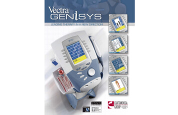
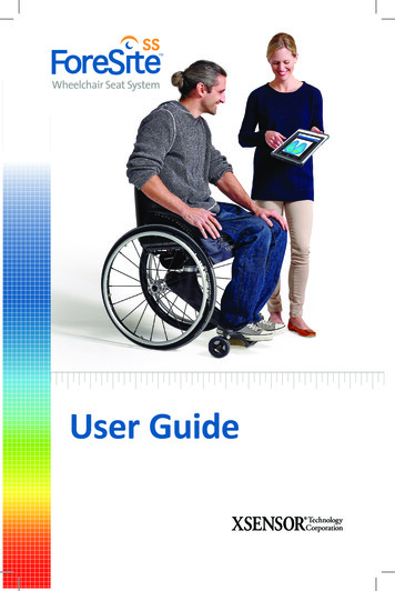
Tablet Terminal Light Indicators:28#COMPONENTSFUNCTION1Docking ConnectorNot applicable for ForeSite SS2USBFor connectivityand/or USB storage devices3LAN / HDMILAN & HDMI Out comboconnector4Mic-in/Line-OutNot applicable for ForeSite SS5DC - JackFor Power Supply connectivityForeSite SS Hardware
Power Supply SpecificationsInput100-240 V AC, 47-63 HzOutput12V DC, 2.5A maxX4 Lithium-Ion Battery SpecificationsMolicel MCR-1821JNominal Voltage7.4 VDCNominal Capacity2400 mAhCaution: Risk of fire, explosion or burns. Do not short circuit, crush, heatabove 100C, incinerate, or disassemble the battery.Caution: Charge only using the XSENSOR X4 and Globtek WR9QD2000MSBN-MED.The battery contains recyclable materials and recycling is encouraged. Somejurisdictions require recycling.Please consult and obey local battery disposal laws.ForeSite SS Hardware29
MaintenanceThe Tablet TerminalIf proper precautions are met in accordance to provided warnings andcautions to protect the Display Terminal, there should be no regularmaintenance required. If damages occur, contact XSENSOR as soon aspossible. Do not attempt repairs on your own.The SensorThe Sensor pad does not require regular maintenance, but periodiccalibration may be required for optimum accuracy. Repairs may ONLYbe performed by the manufacturer or the manufacturer’s authorizedrepresentative. The device may still be used successfully if it is notcalibrated; the frequency of calibration is at the discretion of the user.Wireless Sensor Pack (X4) BatteryThe X4 battery is maintenance free. It is recommended that batteries bekept at room temperature (25 C /- 5 C). Elevated temperatures can resultin shortened battery life.Storage/TransportOnly health care professionals should handle storage and cleaning of thesystem components. All pieces of the system should be stored according tothe following instructions which also appear on the ForeSite SS carry caseinsert.130ForeSite SS Hardware23
Storage Steps1. Place the sensor pad on a flat surface.2. Place the carry case insert along the edge of the sensor pad and securethe sensor cable using the attached elastic straps.3. Roll, wrapping the sensor pad around the carry case insert.4. Store the wrapped sensor pad in the designated sensor carry casecompartment and secure it with the attached straps.Environmental conditions for system storage and transportation:Ambient Temperature-4 to 140 F (-20 to 60 C)Relative Humidity10 to 90%, non-condensingAtmospheric Pressure0.50 to 1.06 barDo not place heavy objects on top of a folded sensor. Store the systemcomponents in the provided protective case(s) when not in use, and avoidleaving pieces of the system lying unprotected or in a place where theremay be a tripping hazard or danger of the system components beingdamaged. If the system is required to be transported to another location,ensure all components are folded and/or safetly put away into theirprotective cases during transport.ForeSite SS Hardware31
CleaningCleaning may be performed if a part of the system becomes accidentallydirty or smudged. It is strongly recommended that only health careprofessionals attempt to perform any type of cleaning on any part of thesystem, as follows:Tablet Terminal The Display Terminal may be wi
4 Introduction Product Compliance: Safety Standards The XSENSOR Pressure Imaging System complies with the following standards: IEC 60601-1:2005, CSA C22.2 No. 60601-1:2008, ANSI/AAMI ES 60601-1/