Transcription
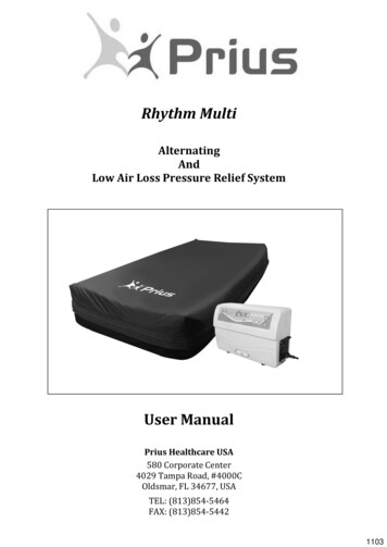
Rhythm MultiAlternatingAndLow Air Loss Pressure Relief SystemUser ManualPrius Healthcare USA580 Corporate Center4029 Tampa Road, #4000COldsmar, FL 34677, USATEL: (813)854-5464FAX: (813)854-544201103
Content1. The Purpose of this Manual .12. Product Description .13-1 Alternation Cycle IllustrationMaster Control Unit FeaturesMattress Features3. Technical Data .2Master Control UnitRhythm Multi Mattress ReplacementSymbol Definition4. Instruction for Proper Use .35. Cleaning.6The MattressThe Master Control UnitReplace Air FilterWaste Disposal6. Storage and Care .77. Maintenance and Troubleshooting.88. EMC Related Notification .99. Warranty . 120
Warning Connect the Master Control unit to a proper power source. Don’t use the system in the presence of any flammable gases,such as anesthetic agents. Keep the blower and mattress away from sources of liquid or open flames. Keep the mattress away from sharp objects. The device is not AP/APG protected. Do not place any heating device near the mattress system.Caution Use the mattress under the physician’s instruction. Periodic re-positioning of the patient is still necessary when using the RhythmMulti low air loss system.The Control unit should only be repaired by an authorized distributor.(The circuit diagram, repairable component parts list, and service manual arereleased only to authorized distributor). Do not drop the control unit. Do not store the system in direct sunlight or in extreme cold conditions.0
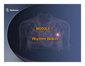
1. The Purpose of this ManualThis operation manual is focused on the setup, cleaning and routine maintenance of theRhythm Multi-Function Air Therapy Support System. We recommend keeping thismanual available to answer questions related to the system.2. Product DescriptionThe Rhythm Multi system is a unique and innovative specialized mattress replacementsystem. The system utilizes low air loss technology with a high flow rate that providespressure management for the treatment of pressure ulcers.The advanced 3:1alternating function also provides active prevention for pressure relief, especially forthose in acute care and long term care facilities. The cells inflate and deflate in a 3:1cycle, meaning 2/3rds of the body is always supported by air at any one time. TheRhythm Multi system offers “deep-cell therapy”; whereby, the cells completely collapseproviding “0” pressure at the point of deflation. The “Soft/Firm” digital control featureallows the caregiver to adjust the firmness or softness of the surface for optimalpatient comfort through 10 different pressure settings. The Rhythm Multi also has a 2inch enclosed convoluted foam base to provide extra protection and comfort for thepatient in the event of a power failure and the mattress deflates.3-1 Alternation Cycle Illustration1
Master Control Unit Features ALTERNATE setting – provides 3 in 1 alternating pressure therapy that can beadjusted from 3 to 20 minutes in 1 minute increments or 20 to 95 minutes in 5minute increments. STATIC setting - provides low air loss therapy without alternation therapy. PULSATE setting - gently raises and lowers the pressure of the entire airmattress every 90 seconds for an alternative to traditional alternating pressure. AUTO FIRM setting - when activated it provides a uniform firmness for nursingprocedures, egress and ingress of the mattress. Power failure audible alarm - in the event of a power failure, an audible alarmwill sound. Once activated the alarm can be disabled by pushing the ALARMRESET button on the front panel. LOCK-OUT feature - allows the caregiver to lock all settings from intentional orunintentional tampering. Double insulated case provides near silent operation. The foot board mounting rack provides convenient placement on the bed.Mattress Features Individual air cushion is designed for maximum pressure distribution. Each air cell is strategically vented to provide true low air loss therapy. The “Happy Heel” feature allows for independent pressure control for heel cells. Integrated glide sheet on bottom cover for easy transfer and noise mitigation. Convenient cable and management system designed in the mattress cover.3. Technical DataMaster Control UnitModel NameModel No.Size ( L x W x H)WeightPhase TimeMax Operating PressureRated VoltageRated FrequencyFuse RatingMax CurrentClassificationOperation TemperatureOperation HumidityMode of OperationStandardRhythm MultiFC-PHR000917.7” x 6.8”x 10.8”13.2 lbs3 9561mmHgAC 110-120V60 Hz5A 250V5AClass I, Type BFNot AP or AGP type15 C 35 C30% 75%ContinuousIEC 60601-1,CAN/CSA C22.2 No. 601.1,IEC 60601-1-22
Rhythm Multi Mattress ReplacementModel NoSize (L x W x H)WeightCells MaterialCover TypeCover MaterialBase MaterialFM-PHR000980” x 36” x 10”28.67 lbsNylon w/ PU backingZipper cover with removable foam baseNylon woven fabric w/ PU coating finishWoven Polyester fabric w/ PVC backingSymbol DefinitionRefer to Accompanying DocumentsWaste DisposalType BF Applied PartAlternating CurrentWarning4. Instructions for Proper Use1. Remove the existing mattress from the bed frame.2. Replace the standard mattress with the Rhythm Multi mattress replacementsystem.3. Position the mattress so the air tube is at the foot of the bed.4. Secure the straps on the bottom cover of the mattress to the bed frame.5. Hang the control unit on the foot board of the bed frame.6. Attach the air tube connector to the sockets on the left panel of the control unit.(connectors and sockets are color coded)7. Check air hoses to ensure they are not kinked under the mattress.8. Plug in the control unit and turn on the master power switch on the right sidepanel and the STANDBY LED will illuminate.9. Push the STANDBY/OPERATE button on the front panel. The OPERATE LEDshould illuminate and the control unit will be operational.3
10. Push the AUTO FIRM button for fast inflation. Allow 4-7 minutes for full inflation.After the mattress is fully inflated the caregiver can transfer the patient to themattress. Note: The mattress can be inflated while a patient is laying on it.11. Push AUTO FIRM again to release the fast inflation mode.12. Static Function: Press the MODE button until the “STATIC” LED is illuminated.The STATIC mode provides True Low Air Loss Therapy. Once the patient ispositioned on the mattress perform a hand check by placing hand under thepatient buttocks between cells and foam. The patient should have at least 2 inchesof clearance between the buttocks and the bottom of the mattress. To adjust thepressure press the SOFT or FIRM button to achieve the maximum patient comfort.13. Pulsate Function: Press the MODE button until the “PULSATE” LED isILLUMINATED. Once activated the mattress will be automatically “pulsate” byslightly deflating the pressure in the mattress for 90 seconds and then re-inflatingto the original pressure setting for 90 seconds. The mattress will continue to cyclein this fashion in the pulsate mode.14. Alternate Function: Press the MODE button until the “ALTERNATE” LED isilluminated. This will enable the 3 in 1 alternating pressure function illustrated onpage 1.4
15. Alternation time can be adjusted by the CYCLE button. The cycle time can be setfrom 3 minutes to 20 minutes in 1 minute increments and 25-95 minutes in 5minute increments. (NOTE: If the STATIC function or PULSATE function isselected the display window will not display a time.)16. The Master Control Unit is equipped with power failure alarm. During a powerfailure, where the unit is not connected to a backup power source, an audiblealarm will sound. The alarm can be disabled by pushing the Alarm Reset button onthe front panel.Caution: Immediate response by the operator is required when the powerfailure alarm is activated.17. LOCK-OUT: The Master Control Unit is also equipped with a manual LOCK OUTfunction. To engage press the LOCK OUT button. When engaged the LOCK OUTLED will be illuminated and all function keys will be automatically disabled.UNLOCKING: To disengage the LOCK OUT function press and hold the “LOCKOUT” button for 3-5 seconds. The LOCK OUT function will also disengage when theunit is shut down.18. CPR Deflation: For quick mattress deflation disconnect the hose connector fromthe Control Unit and Open the CPR quick deflation valve at the head of themattress.RecommendationsMake sure the hoses are not kinked and the connectors are properly locked.The parts and accessories supplied are specifically designed for use with thiscontrol unit. Use of other parts or accessories in conjunction with the system isnot recommended.Caution5The air outlet labelsignifies the blower exhaust. Do not touch the exhaustvalve during operation as the temperature can be very hot.
5. CleaningThe MattressThe mattress should be cleaned weekly using a damp soft cloth and mild detergent.If the top or bottom cover becomes severely soiled remove and replace with a cleancover. The soiled cover can be cleaned as follows.Covers can be washed and thermally disinfected in a washing machine. Whenwashing bottom cover remove all air bladders, hoses, valves and foam padding.(NOTE: Never use phenol based cleaning solutions.)Industrial cleaningPre-WashMain WashMain WashSpin CycleCold RinseSpin CycleDomestic cleaningPre-WashMain WashCold RinseSpin Cyclecold60 C72 Ccold72 C10 min6 min10 min2 min3 min5 min10 min2 min5 minTumble Drying or Tunnel Drying is not recommended.Mattress Cells can be wiped over with a solution of sodium hypochlorite 1000ppm orany other non-phenolic germicidal solution.The Master Control UnitCAUTIONSWITCH OFF THE ELECTRICAL SUPPLY TO THE PUMP AND DISCONNECT THEPOWER CORD FROM THE MAIN SUPPLY BEFORE CLEANING AND INSPECTIONThe master control unit should also be cleaned weekly using a damp soft cloth and milddetergent.The blower casing is manufactured from ABS plastic and if the case is soiled the blowercan be wiped down with a sodium hypochlorite solution to dilution of 1000ppm or anyEPA approved hospital grade disinfectant. (NOTE: Do not use phenol base cleaningsolution.)The air filter should also be cleaned and checked as often as possible at a minimum ofevery six months. The Air Filter can be easily removed by pinching center of the filterand pulling outward from the back of the control unit.6
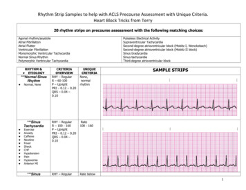
Replace Air Filter1. Remove air filter by pinching center and pulling outward and replace with a newFilter.2. If necessary use a soft bristle brush to remove dust and difficult dried-on soilaround the air filer inlet on the control unit.FilterWaste DisposalThis Product has been supplied from an environmentally awaremanufacturer that complies with the WEEE.This product may contain substances that can be harmful to theenvironment if disposed of in places that are not approved by your state,local or federal laws. Please be environmentally responsible and recyclethis product through your recycling facility at its end of life.6. Storage and CareMaster Control Unit Check the power cord and plug for abrasions and excessive wear. Plug in the unit and verify air flow from the hose connection ports. Place in plastic bag for storage.Mattress Replacement System Check the air manifold for kinks or breaks and replace if necessary. Twist open the CPR plug at the head of the mattress and disconnect the airfeed tubes. All of the air will be expelled. Starting at the head of the mattressroll towards the foot of the bed. Use the base mounted straps to secure. Place the system in a plastic bag for storage.It is recommended that the following guidelines are used whenever the system isbeing stored or transported to another location:Temperature limitations5 C 60 CRelative humidity30% 75%7
7. Maintenance & TroubleshootingNo daily maintenance is required. This equipment should only be serviced by aproperly qualified and authorized technician. For common troubleshooting tips pleaserefer to the chart below.SymptomAir is blowing from the control unitbut mattress is not inflating.Inspection ProcedurePossible Solution1. Check power source.Improper voltage maycause the blower tofunction abnormally anddamage the control unit.1. Verify voltage using voltageregulator.2. Check air tubes for kinks.2. Adjust the air tubes to allowsmooth air flow. Replace ifnecessary.3. Replace with new air cells.3. Check air cells for leakageother than where designed.4. Check air tube connection 4. Check air tube andbetween control unit andconnector for damage.mattress.Replace if necessary.Reconnect hose with controlunit. Replace if necessary.The Control Unit is not functioning.1. Check the power cord and 1. Use a power regulator.the power voltage.2. Check the fuse.2. Replace fuse if necessary.Some of the air cells are not properly 1.Check connection between 1. Adjust air tubes for properinflated.air cells and the manifoldair flow. Replace iffor kinking.necessary.2. Check air cells for leakage 2. Replace air cell if damaged.other than where designed.8
8. EMC Related NotificationGuidance and manufacturer’s declaration – electromagnetic emissionsThe blower is intended for use in the electromagnetic environment specified below. The customer or theuser of the blower is responsible for making sure that it is used in such an environment.Emissions testComplianceElectromagnetic environment – guidanceRF emissionsGroup 1The blower uses RF energy only for its internalfunction. Therefore, its RF emissions are very lowCISPR 11and are not likely to cause any interference innearby electronic equipment.RF emissionsClass BThe blower is suitable for use in all establishments,including domestic establishments and thoseCISPR 11directly connected to the public low-voltage powerHarmonic emissionsClass Asupply network that supplies buildings used forIEC 61000-3-2domestic purposes.Voltage fluctuations/Compliesflicker emissionsIEC 61000-3-3Recommended distances betweenportable and mobile RF communications equipment and the blowerThe blower is intended for use in an electromagnetic environment in which radiated RF disturbances arecontrolled. The customer or the user of the blower can help prevent electromagnetic interference bymaintaining a minimum distance between portable and mobile RF communications equipment(transmitters) and the blower as recommended below, according to the maximum output power of thecommunications equipment.Rated maximumSeparation distance according to frequency of transmitteroutput power ofMtransmitter150 kHz to 80 MHz80 MHz to 800 MHz800 MHz to 2,5 GHzWd 1,2d 1,2d 7,310121223100For transmitters rated at a maximum output power not listed above, the recommended separationdistance d in meters (m) can be estimated using the equation applicable to the frequency of thetransmitter, where P is the maximum output power rating of the transmitter in watts (W) according to thetransmitter manufacturer.NOTE 1: At 80 MHz and 800 MHz, the separation distance for the higher frequency range applies.NOTE 2: These guidelines may not apply in all situations. Electromagnetic propagation is affected byabsorption and reflection from structures, objects and people.9
Guidance and manufacturer’s declaration – electromagnetic immunityThe blower is intended for use in the electromagnetic environment specified below. The customer or theuser of the blower is responsible for making sure that it is used in such an environment.ImmunityIEC 60601 testComplianceElectromagnetic environment – guidancetestlevellevelPortable and mobile RF communications equipmentshould be used no closer to any part of the blower,including cables, than the recommended separationdistance calculated from the equation applicable tothe frequency of the transmitter.Recommended separation distanceConductedRFIEC 610004-6RadiatedRFIEC 610004-33 Vrms150 kHz to 80MHz3 V/m80 MHz to 2,5 GHzd 1,23 Vrms3 V/md 1,280 MHz to 800 MHzd 2,3800 MHz to 2,5 GHzwhere P is the maximum output power rating of thetransmitter in watts (W) according to the transmittermanufacturer and d is the recommended separationdistance in meters (m).Field strengths from fixed RF transmitters, asdetermined by an electromagnetic site survey, ashould be less than the compliance level in eachfrequency range bInterference may occur in the vicinity of equipmentmarked with the following symbol:NOTE 1: At 80 MHz and 800 MHz, the higher frequency range applies.NOTE 2: These guidelines may not apply in all situations. Electromagnetic propagation is affected byabsorption and reflection from structures objects and people.a. Field strengths from fixed transmitters, such as base stations for radio (cellular/cordless) telephonesand land mobile radios, amateur radio, AM and FM radio broadcast and TV broadcast cannot bepredicted theoretically with accuracy. To assess the electromagnetic environment due to fixed RFtransmitters, an electromagnetic site survey should be considered. If the measured field strength in thelocation in which the blower is used exceeds the applicable RF compliance level above, the blowershould be observed to verify normal operation. If abnormal performance is observed, additionalmeasures may be necessary, such as reorienting or relocating theblower .b. Over the frequency range 150 kHz to 80 MHz, field strengths should be less than 3 V/m.10
Guidance and manufacturer’s declaration – electromagnetic immunityThe blower is intended for use in the electromagnetic environment specified below. The customer or theuser of the blower is responsible for making sure that it is used in such an environment.Immunity testIEC 60601Compliance levelElectromagnetic environment –test levelguidanceElectrostatic6 kV contact6 kV contactFloors should be wood, concrete ordischarge (ESD)ceramic tile. If floors are covered with8 kV air8 kV airsynthetic material, the relative humidityIEC 61000-4-2should be at least 30 %.Electrical fast2 kV for power2 kV for powerMain power quality should be that of atypical commercial or hospitaltransient/burstsupply linessupply linesenvironment.IEC 61000-4-4SurgeIEC 61000-4-5interruptionsand voltagevariations onpower supplyinput linesIEC 61000-4-11Powerfrequency(50/60 Hz)magnetic field1 kV forinput/outputlines1 kV line(s) toline(s)1 kV forinput/outputlines1 kV line(s) toline(s)2 kV line(s) toearth 5 % UT( 95 % dip in UT)for 0,5 cycle2 kV line(s) toearth 5 % UT( 95 % dip in UT)for 0,5 cycle40 % UT(60 % dip in UT)for 5 cycles40 % UT(60 % dip in UT)for 5 cycles70 % UT(30 % dip in UT)for 25 cycles70 % UT(30 % dip in UT)for 25 cycles 5 % UT( 95 % dip in UT)for 5 sec 5 % UT( 95 % dip in UT)for 5 sec3 A/m3 A/mMain power quality should be that of atypical commercial or hospitalenvironment.Main power quality should be that of atypical commercial or hospitalenvironment. If the user of the blowerrequires continued operation duringpower main interruptions it isrecommended that the blower bepowered from an uninterruptible powersupply or a battery.Power frequency magnetic fields shouldbe at levels characteristic of a typicallocation in a typical commercial orhospital environment.IEC 61000-4-8NOTE: UT is the a.c. mains voltage prior to application of the test level.11
9. Warranty Prius Healthcare USA guarantees this equipment to be free from defects inmaterial and workmanship for up to 12 months from the date of delivery. All warranty work will be performed at the service address below. At Manufacturers discreton we agree to service, repair or replace any equipmentor part found to be defective at no charge. This warranty excludes equipment damaged through shipping, tampering,improper maintenance, carelessness, accident, negligence, misuse, or which hasbeen altered, repaired or dismantled other than with the manufacture’s writtenauthorization and by its approved procedures and by properly qualifiedtechnicians. In no event shall Prius Healthcare be liable for any direct, indirect orconsequential damage or loss resulting from the use of equipment. Warranty is non-transferrable.12
Prius Healthcare USA580 Corporate Center4029 Tampa Road, #4000COldsmar, FL 34677, USATEL: (813)854-5464FAX: (813)854-54420AL300103 V1.00
4. Instructions for Proper Use 1. Remove the existing mattress from the bed frame. 2. Replace the standard mattress with the Rhythm Multi mattress replacement system. 3. Position the mattress so the air tube is at the foot of the bed. 4. Secure the straps on the bottom cover of the mattress to the bed frame. 5.