Transcription
Eclipse 5 with autoSAT Oxygen ConcentratorTECHNICAL SERVICE MANUAL
TABLE OF CONTENTSGeneral Information . 4Warning and Caution Statements . 4Introduction to the Eclipse 5 Oxygen System . 6Power Cartridge . 19Typical New Power Cartridge Operation Time. 20Charging Algorithm. 22Eclipse 5 Oxygen System Specifications . 7Pulse Dose Mode Specifications . 8Power Accessory Specifications . 8AC Power Supply . 8DC Power Supply. 8Power Cartridge (Battery) . 8Independent Safety Testing . 9Electromagnetic Compatibility . 10Guidance and Manufacturer’s Declarations . 10Training The Patient .23Introduction . 23Pre-Delivery Check List . 23Indications for Use . 24Contraindications . 24Basic Concept Training . 24Safety Guidelines and Operational SafetyWarnings/Caution. 24Locating the Eclipse 5 for Proper Use andVentilation. 25How The Eclipse 5 Works . 12Introduction . 12ATF Concentrator Module. 12Compressor and Compressor Enclosure . 13Power Distribution . 13Control Board . 13Control Panel . 14User Controls & System Status Indicators . 14Continuous Flow Mode . 15Pulse Dose Mode . 15Provider Mode Functions . 16Alarm Code . 16Pulse Mode Sensitivity Adjustment . 16Hours of Operation . 169V Battery Status . 16Rise Time (Bolus Delivery) . 16Software Version . 16Service Mode Functions . 17Eclipse 5 Data Acquisition Tool (EDAT) . 17Power Supplies . 18AC Power Supply . 18DC Power Supply. 18The Users Manual . 25Showing Panel Buttons, Indicators, Alerts andAlarms . 25Showing Power Cartridge Power Level . 26Selecting the Proper Flow Mode and Setting . 26Selecting Continuous Flow Mode . 26Selecting Pulse Dose Mode . 26“Power Cartridge (Battery) Conservation” Feature. 27Adjusting the Pulse Mode Sensitivity Setting . 27Adjusting Rise Time . 28Connecting the AC Power Supply . 28Connecting the DC Power Supply . 29Active Lifestyle Training. 29Attach the Universal Cart . 30Using Around the House . 30Traveling by Vehicle . 30Traveling by Air . 32Traveling by Cruise Ship . 32Traveling by Train . 32Eclipse 5 Maintenance . 33Weekly Maintenance—Patient . 33Clean the Air Inlet Filter . 33Clean and Care for the Tubing and Cannula . 33
TABLE OF CONTENTS (CONTINUED)Clean the Cabinet and Control Paneland Power Supplies . 33Monthly Maintenance—Patient . 34Care for the Power Cartridge . 34Calibrating the Power Cartridge . 34Patient Training Checklist . 35Annual Maintenance—Provider .36Introduction . 36Annual Maintenance Check List . 36Checking and Replacing the Power Cartridge. 36Eclipse 5 Monthly Run-Time Cycle . 36Annual Maintenance Procedures . 37Removing the Unit Cover . 37Remove and Replace 9 Volt Battery . 41Remove and Replace HEPA Filter. 42Internal Filters . 42Remove and Replace the CompressorIntake Filter. 44Reinstalling or Replacing the Unit Cover . 46Test Procedures . 47Purity and Flow Rate TestProcedure - Preferred Method . 47Purity and Flow Rate Test ProcedureAlternate Method . 47Assembly and Alarm Verification Tests . 48Record Hours of Operation & SoftwareVersion . 49Electrical Safety Test . 50Cleaning the Eclipse 5. 50Provider Service and Maintenance Record . 51Shipping and Transporting the Eclipse 5 . 52Storing the Eclipse 5 . 52Discarding . 52Troubleshooting, Service, andRepair Procedures . 53System Troubleshooting and Alarms. 54Alarm Conditions and Alarm Codes . 57Malfunction Codes . 59System Schematics and Diagrams . 60Oxygen Circuit . 62Remove and Replace the ATF Module. 62Remove and Replace the Product TankAssembly (PN 4378-SEQ) Eclipse 5 . 66Electronics . 69Remove and Replace the ControlBoard Assembly . 69Remove and Replace the Buzzer Wire Harness. 71Control Board Connector Diagram . 72Remove and Replace the Power ManagerPrinted Circuit Board . 73Compressor . 77Remove and Replace the Compressor Box 77Maintenance and Replacement Parts . 81Preventative Maintenance Parts . 81Replacement Parts List . 81Optional Accessories . 82CAIRE Inc. Customer Service ContactInformation . 833
GENERAL INFORMATIONThis technical manual will familiarize you with Provider-specific information regarding the Eclipse 5 OxygenSystem. Instructions in this manual are intended to help ensure that:- Providers are familiar with Eclipse 5 system components and system principles of operation- Providers are given proper guidance in the use of the Eclipse 5 and its accessories that canbe conveyed to patients- Providers are made aware of the care, diagnostics, maintenance, and repair of the Eclipse 5Warning and Caution StatementsSafety instructions are defined as follows:WARNING:Important safety information for hazards that mightcause serious injury.CAUTIONImportant information for preventing damage to the Eclipse 5.NOTE:Places emphasis on an operating characteristic orimportant consideration.Oxygen Concentrator Technical Service Manual PN 20631679 Rev G4
Drip Proof Equipment IP22: The Eclipse 5 and theAC power supply provideprotection against the harmfuleffects of ingress of liquids(IP22 per IEC 60529)Internal SymbolsExternal Power IndicatorPower Cartridge (battery)Status GaugePower Cartridge SymbolAAmperes02Oxygen OutputRecycle SymbolFAA Approved Symbol:The U.S. Federal AviationAdministration (FAA) hasapproved this device foruse on-board commercialaircraft.Flow Setting IndicatorPulse Mode OperationDevice operating normally;power buttonStacking limit by number. Reg. # 2403ISO 7010: Graphical symbols—Safety colorsand safety signs—Registered safety signsThe instruction manual mustbe read. Reg. # M002Keep away from openflame, fire, sparks. Openignition source and smokingprohibited. Reg. # P003Do not smoke near unit orwhile operating unit. Reg. #P002Council Directive 93/42/EEC; concerningmedical devicesAuthorized representative inthe European CommunityThis device complies withthe requirements of Directive93/42/EEC concerningmedical devices. It bears theCE marking as shown.IEC 60417Increase Flow SettingClass II Equipment, DoubleInsulated Reg. # 5172Decrease Flow SettingAlternating Current Reg. #5032ISO 7000; Graphical symbols for use onequipment—Index and synopsisStorage temperature limitationrange is -4 F to 140 F (-20 Cto 60 C). Reg. # 0632Portable humidity range is 15 to 95%.Base humidity range is 30 to 75%.Reg. # 2620Atmospheric pressure limitation. Reg.# 2621Operator’s manual; operating instructions. Reg. # 1641Name and address ofmanufacturer. Reg. # 3082Date of manufacturer. Reg. #2497Catalog Number. Reg. #2493Serial Number. Reg. # 2498This way up. Reg. # 0623Fragile, handle with care.Reg. # 0621Keep away from rain, keep dry. Reg.# 0626Direct Current Reg. # 5031Type BF applied part (degreeof protection against electricshock). Reg. # 5333CSA CertificationCertified for both the U.S.and Canadian markets, to theapplicable U.S. and Canadianstandards.IEC 60601-1-8Low Priority TechnicalAlarmFCC NOTICE:This device may containCYBLE-022001-00, including theantenna 2450AT18B100 from JohnsonTechnology, complies with par 15 ofthe FCC rules. The device meets therequirements for modular transmitterapproval as detailed in FCC publicNotice DA00-1407. Transmitteroperation is subject to the following twoconditions (1) This device may not causeharmful interference, and (2) This devicemust accept any interference received,including interference that may causeundesired operation.This product may be covered by oneor more patents, US and international.Please visit our website below for thelisting of applicable patents. Pat.: patents.gtls.io.Aircraft Use:CAIRE confirms that this machine meetsthe Federal Aviation Administration(FAA) requirements (RTCA/DO-160,section 21, category M) for all phases ofair travel.FCC Notice21 CFR 801.15: Code of Federal RegulationsTitle 21Federal law restricts thisdevice to sale by or on theorder of a physician.Council Directive 2012/19/EU: waste electricaland electronic equipment (WEEE)Wireless TechnologyTechnology usedBluetoothConnection typesSSP, iAP2, GATTFrequency2402 to 2480 MHzMax RF power output 4 dBmOperating range10m (Class 2)It is recommended that the machine is at aminimum distance of 0.43” (1.1 cm) from thebody during operation. Not applicable to masks,air tub- ing, or accessories.WEEEIEC 60601-1: Medical electrical equipmentPart 1 General requirements for basic safetyand essential performanceOxygen Concentrator Technical Service Manual PN 20631679 Rev G5
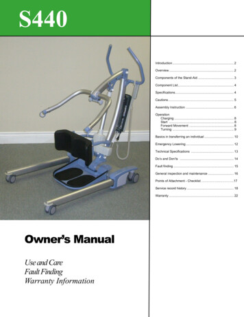
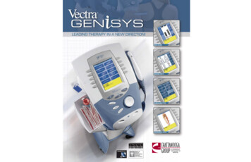
INTRODUCTION TO THE ECLIPSE 5 OXYGEN SYSTEMECLIPSE 5AC POWER SUPPLYWITH NEMA POWER CORDPN: 5941-SEQ (three LED model)PN: 20852326S (with IEC type A cord), 20852325S(with IEC type C cord), and 20852324S (with IECtype G cord) (two LED model)UNIVERSAL CARTDC POWER SUPPLYPN: 5942-SEQPOWER CARTRIDGE(BATTERY)PN: 5991-SEQPN: 7082-SEQHandleControl PanelEDAT Service Port(Not for Patient Use)Air InletFilterOxygenOutlet PortExternal PowerReceptacleCartAttachment LocationFAAApprovalIconFAAApprovalIconPower CordRetainerPowerCartridge(battery)Exhaust VentRating Label &Serial NumberLocationPower Cartridge LatchFRONTBACKOxygen Concentrator Technical Service Manual PN 20631679 Rev G6
ECLIPSE 5 OXYGEN SYSTEM SPECIFICATIONSOxygen ConcentratorDimensions (H x W X D)19.3 x 12.3 x 7.1 inches(49.0cm x 31.2cm x 18.0cm)Weight15.0 poundsEclipse 53.4 poundsPower CartridgeFlow SettingsContinuous Flow (measured in Liters Per Minute LPM) Pulse 0.5 to 3.0 LPM (0.5 liter increments)Dose (measured in mL)Settings 1.0-6.0: 16mL, 24mL, 32mL, 40mL, 48mL, 56mL, 64mL, 72mL, 80mL, 88mL, 96mLSettings 7-9: 128mL, 160mL, 192mLContinuous Flow AccuracyOxygen ConcentrationMaximum System PressureOxygen Output PressureOxygen ConcentrationStatus IndicatorNominal Sound Level3.0 LPM Continuous Flow3.0 Pulse Dose ModeOperating EnvironmentTemperatureHumidityStorage Environment TemperatureHumidityAltitudeNominal Power0.5 LPM Continuous flow 3 LPMContinuous Flow1.0 Pulse Dose Setting6.0 Pulse Dose Setting BatteryChargingNominal Power Cartridge operating time* ContinuousFlow2.0 LPM3.0 LPMPulse Dose (@ 12 BPM)Setting 2.0Setting 6.0Outlet PressureContinuous Flow IndicationAudible Alarm Indicators /- 10% or 200ml/min, whichever is greater87–95.5% for all flow settings14 psig (96.5 kPa)5.0 psig (34.5 kPa) nominalGreen Light Normal OperationYellow Light Warning or Caution, less than 85% 3%Red Light Flashing Abnormal Operation, less than 70% 5% (Note: only for 3-LED models)48 dB(A)40 dB(A)Less than 57 dB while alarming50º F to 104º F ( 10 to 40 C)10% to 95%, Non-condensing, 82.4 F (28 C) Maximum Dew point-4º F to 140º F (-20 to 60 C)Up to 95% Non-condensing0 – 13,123 feet (0 - 4,000 meters)48 Watts145 Watts45 Watts95 Watts50 Watts2.0 hours1.3 hours5.2 hours3.5 hours* Note: Times will decrease with higher bolus size, breath rate, ambient temperature, powercartridge age and use over time.Nominal: 7.0 psigMaximum: 14.0 psigExpressed in liters per minute (LPM) Loss of Power/Hot Power Cartridge Low Power Cartridge/Warm Power Cartridge Low Oxygen Output O2 Flow Outside Normal Limits Unit Malfunction Low 9V battery (Note: only for 3-LED model)Oxygen Concentrator Technical Service Manual PN 20631679 Rev G7
Back-Up Alarm Power9V Internal BatteryFiltersAir Inlet, HEPA, Compressor IntakeDevice ClassificationIEC Class I, Type B Applied Part, IP0 (3 LED model)IEC Class II, Type BF Applied Part, IP22 (2 LED model)Pulse Dose Mode SpecificationsPulse SettingsTrigger Sensitivity1.0 to 6.0: 16mL, 24mL, 32mL, 40mL, 48mL, 56mL, 64mL, 72mL, 80mL, 88mL, 96mL;7-9: 128mL, 160mL, 192mLAdjustable between settings of 1 (most sensitive) to 3 (least sensitive)Adjustable Bolus Rise TimeAdjustable settings of Fast(factory setting), Medium, or SlowTrigger Criteria Cannula pressure has dropped below the trigger point (typically between 0.135—0.37 cm of H2Oof negative pressure) At least 1¼ seconds has passed since the last pulse began1.25 seconds (max. 3 consecutive breaths)Minimum time between breathsWhile in Pulse Dose Mode, the Eclipse 5 is always monitoring for breath detection. After 15 seconds of nobreath detected, the Eclipse 5 “delivers” Continuous Flow at the last Continuous Flow setting.After another 15 seconds, the Eclipse 5 stops delivering Continuous Flow and waits 15 seconds for abreath. The Eclipse 5 will stay in this modality until a breath is detected. (See Power CartridgeConservation Feature, page 26.)Response to Missing BreathsBOLUS VOLUME ( /- 15%)The expected service life is a minimum of 5 years.Pulse DoseSettingBolus Size( 15%) mL1.02.03.04.05.06.0789163248648096128160192AC Power Supply and PowerCartridge (Battery)Max BreathRateDC Power SupplyMax : Bolus volume decreases as breath rate exceeds published range.Power Accessory SpecificationsAC Power SupplyInput Voltage100-240VAC, 50-60 HzInput Power245-260 VAPower Cartridge (Battery)Output voltageQuantity (2) 97.5 W-hrs batteriesOutput Voltage28 VDCCapacityOutput Power200WNominal PowerCartridge LifeDC Power SupplyInput Voltage11.5-16VDCOutput Voltage26 VDCOutput Power150W Max14.8 VDCPowerCartridgeRecharge Time(Each containing 7.92 grams equivalent Lithium content)80% Capacity after 500 Charge/Discharge cycles1.8 to 5.0 hours, dependent on flow setting, to achieve 80%capacity from a fully discharged Power CartridgeOxygen Concentrator Technical Service Manual PN 20631679 Rev G8
Independent Safety TestingEclipse System and Eclipse ConcentratorSafetyIEC 60601-1 :1988 A1 :1991 A2 :1995 Corrigendum (6/95)EN 60601-1(1990) A1(1993) A2(1995) A12(1993) A13(1996) Corrigenda (7/94)ElectromagneticCompatibilityFCC 15B (Sec. 107 & 109), EN55011, EN60601-1-2 :2014 and EN 60601-1-2:2015: ETSI EN301 489-1 V2.1.1 and ETSI EN 301489-17 V3.1.1 (2017-02); EN6100-3-2, EN61000-3-3,IEC61000-4-2, IEC61000- 4-3, IEC61000-4-4, IEC61000-4-5, IEC61000-4-6, IEC61000-4-8,IEC61000-4-11, IEC 60601-1-2 :2001, RTCA DO 160 Rev GAC Power Supply (3 LED model, Model 5941)SafetyElectromagneticCompatibilityIEC 60601-1:1988 A1:1991 A2:1995FCC 15B (Sec. 107 & 109), EN55011, EN60601-1-2 :2001, EN6100-3-2, EN61000-3-3, IEC61000-4-2,IEC61000-4-3, IEC61000-4-4, IEC61000-4-5, IEC61000-4-6, IEC61000-4-8, IEC61000-4-11, EN550141AC Power Supply (2 LED , 3rd Edition, ANSI / AAMI ES60601-1, CSA 22.2 No. 60601-1, EN60601-1, 3rd Edition, CE Mark(LVD)Emissions: EN55011, FCC Part J15, Class B, Conducted, EN55011, FCC Part J15, Class B, RadiatedEN61000-3-2, EN61000-3-3, EN61000-4-2, EN61000-4-3, EN61000-4-4, EN61000-4-5, EN61000-4-6,EN61000-4-11DC Power Supply, Model 5942SafetyElectromagneticCompatibilityPortions of IEC 60601-1:1988 A1:1991 A2:1995FCC 15B (Sec. 107 & 109), EN55011, EN60601-1-2 :2014 and EN 60601-1-2:2015: ETSI EN301 489-1 V2.1.1 and ETSI EN 301489-17 V3.1.1 (2017-02); EN6100-3-2, EN61000-3-3,IEC61000-4-2, IEC61000- 4-3, IEC61000-4-4, IEC61000-4-5, IEC61000-4-6, IEC61000-4-8,IEC61000-4-11, IEC 60601-1-2 :2001, RTCA DO 160 Rev GPower Cartridge 2400, PN 7082SafetyElectromagneticCompatibilityIEC 62133:2013 and IEC 62133 (edit), UL60950-1, First Edition (UL File MH29443), IEC 606011:1988 A1:1991 A2:1995, UN Transportation Tests T1-T8FCC 15B (Sec. 107 & 109), EN55011, EN60601-1-2 :2014 and EN 60601-1-2:2015: ETSI EN301 489-1 V2.1.1 and ETSI EN 301489-17 V3.1.1 (2017-02); EN6100-3-2, EN61000-3-3,IEC61000-4-2, IEC61000- 4-3, IEC61000-4-4, IEC61000-4-5, IEC61000-4-6, IEC61000-4-8,IEC61000-4-11, IEC 60601-1-2 :2001, RTCA DO 160 Rev GAny CSA-CUS mark for the Eclipse 5 system does not encompass operation with the DC Power Supply Model 5942.Oxygen Concentrator Technical Service Manual PN 20631679 Rev G9
ELECTROMAGNETIC COMPATIBILITYThis equipment has been tested and found to comply with the limits for medical devices to the IEC60601-1-2 ElectromagneticCompatibility standard. These limits are designed to provide reasonable protection against harmful interference in a typicalmedical installation. This equipment generates, uses, and can radiate radio frequency energy and, if not installed according to theinstructions, may cause harmful interference to other devices in the vicinity. There is, however no guarantee that interference willnot occur in a particular installation. If this equipment does cause harmful interference to other devices, which can be determinedby turning the equipment off and on, the User is encouraged to try to correct the interference by one or more of the followingmeasures: Reorient or relocate the receiving device. Increase the separation distance between the equipment. Connect the equipment into an outlet on a circuit different from that which the other device(s) are connected. Consult with CAIRE’s Technical Support Department for help.Medical Electrical Equipment needs special precautions regarding EMC and needs to be installed and put into service accordingto the EMC information provided in this manual.Portable and mobile RF communications equipment can affect Medical Electrical Equipment.The use of Accessories, transducers, and cables other than those specified, with the exception of transducers and cables sold bythe Manufacturer of this device as replacement parts for internal components, may result in increased Emissions or decreasedImmunity of the Eclipse 5.The Eclipse 5 should not be used adjacent to or stacked with other equipment and that if adjacent or stacked use is necessary, theEclipse 5 should be observed to verify normal operation in the configuration in which it will be used.Guidance and Manufacturer’s Declaration—Electromagnetic EmissionsThe Eclipse 5 is intended for use in the electromagnetic environment specified below. The customer or the user of the Eclipse 5should assure that it is used in such an environment.Emissions TestComplianceElectromagnetic Environment - GuidanceThe device uses RF energy only for its internal function. Therefore, its RFRF emissionsGroup 1emissions are very low and are not likely to cause any interference in nearbyCISPR 11electronic equipment.RF emissionsClass BCISPR 11The device is suitable for use in all establishments, including domesticHarmonic emissionsClass Aestablishments and those directly connected to the public low-voltage powerIEC 61000-3-2supply network that supplies buildings used for domestic purposes.Voltage fluctuations/ flickerCompliesemissionsIEC 61000-3-3Oxygen Concentrator Technical Service Manual PN 20631679 Rev G10
Guidance and Manufacturer’s Declaration—Electromagnetic ImmunityThe Eclipse 5 is intended for use in the electromagnetic environment specified below. The customer or the user of the Eclipse 5should assure that it is used in such an environment.Immunity testCompliance levelElectrostatic discharge (ESD) IED 8 kV contact61000-4-2 15 kV airElectromagnetic environment – guidanceFloors should be wood, concrete or ceramic tile. If floors arecovered with synthetic material, the relative humidity shouldbe at least 30 %.Electrical fast transient/burst 2 kVMains power quality should be that of a typicalcommercial or hospital environment.Surge 1 kVIEC 61000-4-5 2 kVMains power quality should be that of a typicalcommercial or hospital environment.IEC 61000-4-4100V-240VVoltage dips, short interruptionsand voltage variations on powersupply input lines IEC 61000-4-11Power frequency magnetic fieldIEC 61000-4-830A/mConducted RF10 VrmsIEC 61000-4-8150 kHz to 80 MHzRadiated RF9 V/m to 85 V/mIEC 61000-4-6At frequencies, up to 5.785GHzMains power quality should be that of a typical commercial orhospital environment. If the user of the Eclipse 5 requirescontinued operation during power mains interruptions, it isrecommended that the Eclipse 5 is powered from anuninterruptible power supply(UPS).Power frequency magnetic fields should be at levelscharacteristic of a typical location in a typical commercial orhospital environment.The Eclipse 5 complies with all applicable electromagneticcompatibility requirements (EMC) according to IEC 60601-12:2014, for residential, commercial and light industryenvironments. Portable and mobile RF communicationsequipment should be used no closer to any part of themachine, including cables, than the recommended 10cmseparation distance. The Eclipse 5 has been designed to meetEMC standards. However, should you suspect that the machineperformance (e.g. pressure or flow) is affected by otherequipment, move the machine away from the possible cause ofthe interference.The Eclipse 5 complies with Part 15 of the FCC rules andindustry Canada license-exempt RSS standards. Operation issubject to the following two conditions: this machine may notcause harmful interference, and this machine must accept anyinterference revived, including interference that may causeundesired operation.FCC ID: WAP2001Oxygen Concentrator Technical Service Manual PN 20631679 Rev G11
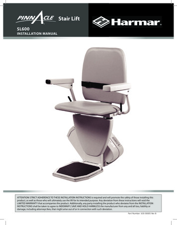
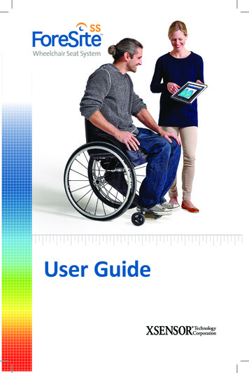
How The Eclipse 5 WorksINTRODUCTIONThe Eclipse 5, Personal Ambulatory Oxygen System with autoSAT Technology is a portable medical device used to extractoxygen from the atmosphere, concentrate it to 87–95.6% and present the oxygen to the patient. The device will operate inContinuous Flow Mode or Pulse Dose Mode. In Continuous Flow Mode the oxygen is provided at a constant flow rate between0.5 and 3.0 LPM. In Pulse Dose Mode, oxygen is supplied in a bolus at the beginning of each inspiration, providing a selectablerange setting of 16mL to 192mL.The Eclipse 5 operates from either external power or from an internal rechargeable Power Cartridge. The system includes a“Smart” battery charger that recharges the internal Power Cartridge whenever the Eclipse 5 is connected to AC or DC power.The system monitors and controls both the power source and the Power Cartridge charger.Figure 1: Eclipse 5 System Block DiagramATF CONCENTRATOR MODULEThe Eclipse 5 uses a passive system to separate oxygen from air. Air flows into the Eclipse 5 where it is filtered and thenenters the compressor. Pressurized air flows from the compressor into the ATF Concentrator Module where it is separatedinto oxygen and nitrogen components. The air separation process uses a rotary valve system to force air through a series ofpressurized sieve beds. Through a process known as “vacuum pressure swing adsorption,” nitrogen molecules are collected onan adsorbent material allowing the concentrated oxygen to be forced through a sieve bed into the product tank. The nitrogenmolecules are then purged from the adsorbent material using a vacuum pressure cycle.Oxygen flows from the product tank through a HEPA filter and past a sensor that measures flow and concentration. A flowcontrol valve regulates the flow of concentrated oxygen presented to the patient. The process is continuously repeated duringoperation.Oxygen Concentrator Technical Service Manual PN 20631679 Rev G12
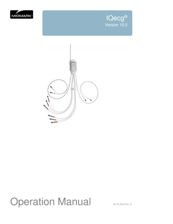
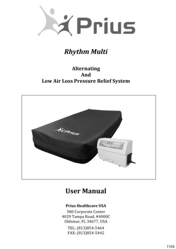
COMPRESSOR AND COMPRESSOR ENCLOSUREThe Eclipse 5 Compressor is a two-cylinder, variable speed wobble piston compressor, driven by a highly efficient BrushlessDC (BLDC) motor. When air flows into the Compressor enclosure, it passes through an air intake filter/muffler that mufflessound and filters out impurities. Using one cylinder, the compressor takes in filtered air and delivers it to the ATF Moduleunder pressure. The second cylinder draws a vacuum on the ATF module and exhausts nitrogen rich gas to the exhaust vent.Using a multifaceted approach, sound, heat, and vibration generated by the compressor are mitigated by the compressorenclosure. Vibration and structure-borne noise are addressed by the dual axis gimbal that supports the compressor and thetubing that connects the compressor to the ATF module. The rigid walls of the compressor enclosure and the sound adsorbingfoam that lines it diminish the radiated noise. The centrifugal blower mounted within the compressor enclosure serves toefficiently draw cooling air in over the compressor cylinders while simultaneously pushing exhaust gas out of the concentrator.POWER DISTRIBUTIONThe Power Manager takes external power that comes into the Eclipse 5 from the power supplies or Power Cartridge andmonitors and controls power distribution to the rest of the Eclipse 5 system. The Power Manager drives the compressor, ATFmodule motor, blower, and provides power to the Control Board. In addition, when the unit is connected to an external powersource, the power manager monitors and controls the recharging of the Power Cartridge.CONTROL BOARDThe Control Board is at the center of nearly all Eclipse 5 functions. The board constantly monitors dynamics such as temperatures,pressures, product flow and concentration, and user input. It determines proper compressor and ATF motor speeds needed inorder to provide optimum system performance. In addition, this system supports the operation of the Control Panel and itsindicators.The Control Board utilizes a proprietary ultrasonic flow and concentration sensor and a flow control valve to accurately controlthe flow of oxygen in Continuous Flow and Pulse Dose Modes.Product PressureControl BoardFigure 2: Flow Sensor Board DiagramOxygen Concentrator Technical Service Manual PN 20631679 Rev G13
CONTROL PANELThe control panel provides a user interface consisting of a membrane panel keyboard, Liquid Crystal Display (LCD), external power present indicator,Power Cartridge capacity indicator, alarm status indicators, and an audio transducer. The user interface informs the user of the system status andallows the user to set the desired flow rate and flow mode.User Control Panel (3 LED model)ON/OFF Button (Green) Indicator: This button powersthe device ON or OFF. The Green Indicator isilluminated when the device is ON and functioningproperly.Increase or Decrease Flow Setting Buttons: Use these buttonsto set the flow to your prescribed setting.Delivery Mode Button and Indicator: The button toggles betweenContinuous Flow and Pulse Dose Mode. The Pulse Dose Mode activatesautoSAT Technology and allows a significant increase in the operatingtime while powered by the battery. When the Pulse Dose Mode isactivated, the green Pulse Dose Mode Indicator illuminates and a pulse ofoxygen is delivered with each inspiratory effort.ALERT (Yellow) Indicator—Low and Medium Priority Alerts: Whenilluminated, this indicates a low priority awareness condition or Caution.Continue to use your system and refer to the Troubleshooting Table forthe proper response, or contact your Home Care Provider. A flashingyellow indicates a medium priority alert. A prompt response is necessary.(Typically low oxygen or low battery.)ALARM (Red) Indicator—High Priority Alarms: Indicates a high priorityalarm condition. An immediate respons
System. Instructions in this manual are intended to help ensure that: - Providers are familiar with Eclipse 5 system components and system principles of operation - Providers are given proper guidance in the use of the Eclipse 5 and its accessories that can be conveyed to patients