Transcription
ELITE TiInstallation ManualENGLISHlowrance.com
PrefaceDisclaimerAs Navico is continuously improving this product, we retain theright to make changes to the product at any time which may not bereflected in this version of the manual. Please contact your nearestdistributor if you require any further assistance.It is the owner’s sole responsibility to install and use the equipmentin a manner that will not cause accidents, personal injury orproperty damage. The user of this product is solely responsible forobserving safe boating practices.NAVICO HOLDING AS AND ITS SUBSIDIARIES, BRANCHES ANDAFFILIATES DISCLAIM ALL LIABILITY FOR ANY USE OF THIS PRODUCTIN A WAY THAT MAY CAUSE ACCIDENTS, DAMAGE OR THAT MAYVIOLATE THE LAW.Governing Language: This statement, any instruction manuals, userguides and other information relating to the product(Documentation) may be translated to, or has been translated from,another language (Translation). In the event of any conflict betweenany Translation of the Documentation, the English language versionof the Documentation will be the official version of theDocumentation.This manual represents the product as at the time of printing.Navico Holding AS and its subsidiaries, branches and affiliatesreserve the right to make changes to specifications without notice.CopyrightCopyright 2016 Navico Holding AS.WarrantyThe warranty card is supplied as a separate document.In case of any queries, refer to the brand website of your unit orsystem: www.lowrance.com.Regulatory statementsThis equipment is intended for use in international waters as well ascoastal sea areas administered by the USA, and countries of the E.U.and E.E.A.Preface ELITE Ti Installation Manual3
This equipment complies with: CE under 2014/53/EU Directive The requirements of level 2 devices of the Radio communications(Electromagnetic Compatibility) standard 2008 Part 15 of the FCC Rules. Operation is subject to the followingtwo conditions: (1) this device may not cause harmfulinterference, and (2) this device must accept any interferencereceived, including interference that may cause undesiredoperation.The relevant Declaration of conformity is available on the followingwebsite: www.lowrance.com.Industry CanadaIC RSS-GEN, Sec 7.1.3 Warning Statement- (Required forlicense exempt devices)This device complies with Industry Canada license-exempt RSSstandard(s). Operation is subject to the following two conditions: (1)this device may not cause interference, and (2) this device mustaccept any interference, including interference that may causeundesired operation of the device.Le présent appareil est conforme aux CNR d’IndustrieCanada applicables aux appareils radio exempts de licence.L’exploitation est autorisée aux deux conditions suivantes: (1)l’appareil ne doit pas produire de brouillage, et (2) l’utilisateur del’appareil doit accepter tout brouillage radioélectrique subi, même sile brouillage est susceptible d’en compromettre le fonctionnement.WarningThe user is cautioned that any changes or modifications notexpressly approved by the party responsible for compliance couldvoid the user’s authority to operate the equipment.This equipment generates, uses and can radiate radio frequencyenergy and, if not installed and used in accordance with theinstructions, may cause harmful interference to radiocommunications. However, there is no guarantee that theinterference will not occur in a particular installation. If thisequipment does cause harmful interference to radio or televisionreception, which can be determined by turning the equipment off4Preface ELITE Ti Installation Manual
and on, the user is encouraged to try to correct the interference byone or more of the following measures: Reorient or relocate the receiving antenna Increase the separation between the equipment and receiver Connect the equipment into an outlet on a circuit different fromthat of the receiver Consult the dealer or an experienced technician for helpInternet usageSome features in this product use an internet connection toperform data downloads and uploads. Internet usage via aconnected mobile/cell phone internet connection or a pay-per-MBtype internet connection may require large data usage. Your serviceprovider may charge you based on the amount of data you transfer.If you are unsure, contact your service provider to confirm rates andrestrictions.Countries of intended use in the EUAT - AustriaBE - BelgiumBG - BulgariaCY - CyprusCZ - Czech RepublicDK - DenmarkEE - EstoniaFI - FinlandFR - FranceDE - GermanyGR - GreeceHU - HungaryIS - IcelandIE - IrelandIT - ItalyLV - LatviaLI - LiechtensteinLT - LithuaniaPreface ELITE Ti Installation Manual5
LU - LuxembourgMT - MaltaNL - NetherlandsNO - NorwayPL - PolandPT - PortugalRO - RomaniaSK - Slovak RepublicSI - SloveniaES - SpainSE - SwedenCH - SwitzerlandTR - TurkeyUK - United KingdomTrademarksLowrance and Navico are registered trademarks of Navico.Navionics is a registered trademark of Navionics, Inc.NMEA and NMEA 2000 are registered trademarks of the NationalMarine Electronics Association.Fishing Hot Spots is a registered trademark of Fishing Hot Spots Inc.Copyright 2012 Fishing Hot Spots.C-MAP is a registered trademark of C-MAP.SD and microSD are trademarks or registered trademarks ofSD-3C, LLC in the United States, other countries or both.Wi-Fi is a registered trademark of the Wi-Fi Alliance .Additional mapping data: Copyright 2012 NSI, Inc.: Copyright 2012 by Richardson’s Maptech.Bluetooth is a registered trademark of Bluetooth SIG, Inc.Power-Pole is a registered trademark of JL Marine Systems, Inc.C-Monster is a trademark of JL Marine Systems, Inc.Navico product referencesThis manual refers to the following Navico products:6Preface ELITE Ti Installation Manual
Broadband Sounder (Broadband Sounder)DownScan Overlay (Overlay)GoFree (GoFree)INSIGHT GENESIS (Insight Genesis)StructureMap (StructureMap)StructureScan (StructureScan)StructureScan HD (StructureScan HD)About this manualThis manual is a reference guide for installing the ELITE Ti.Important text that requires special attention from the reader isemphasized as follows:Ú Note: Used to draw the reader’s attention to a comment orsome important information.Warning: Used when it is necessary to warnpersonnel that they should proceed carefully toprevent risk of injury and/or damage to equipment/personnel.Preface ELITE Ti Installation Manual7
8Preface ELITE Ti Installation Manual
Contents11 Check the contents12 Overview121314Front controlsRear connectionsCard reader15 Installation15161819Mounting locationQuick release bracket mountingU-bracket mountingPanel mount22 Mounting the transducer22222425ResearchSelect a transducer locationAttaching the transducerAdjusting the transducer26 Wiring2627272830GuidelinesPower connectionTransducer connectionNMEA 2000 backboneNMEA 0183 device connection32 Software Setup3232333535373739393942First time startupTime and DateData source selectionDevice listDiagnosticsDampingSonar setupStructureScanAutopilot setupFuel setupWireless setupContents ELITE Ti Installation Manual9
4848485050Bluetooth wireless technologyNMEA 2000 setupNMEA 0183 setupTouchscreen calibrationSoftware updates and data backup54 Accessories545455NMEA 2000ELITE Ti accessoriesSonar accessories56 Supported data5660NMEA 2000 compliant PGN ListNMEA 0183 supported sentences62 Technical icalInterfaces64 Dimensional drawings6464656510ELITE-5Ti Dimensional drawingsELITE-7Ti Dimensional drawingsELITE-9Ti Dimensional drawingsELITE-12Ti Dimensional drawingsContents ELITE Ti Installation Manual
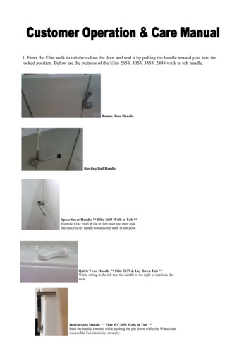
1Check the contents2345617InstInstallatiInstallatioon MaInstallation Manualalla n M nuation an lMa ualnualENGLISHENGLISHENGLISHENGLISHbandg.cband omg.cband omg.cband omg.com812911101Sun cover2ELITE Ti3Quick release mounting bracket (ELITE-5Ti and ELITE-7Tionly)4U bracket (ELITE-9Ti and ELITE-12Ti only)5Quick release bracket locking bolt and knob. (ELITE-7Ti only)6Documentation pack7Fuse holder (ATC blade)8U bracket knobs (2x) (ELITE-9Ti and ELITE-12Ti only)9Fuse (3 amp)10 7-pin to 9-pin transducer adapter cable. Included only withunits that do not include transducers.11 Bracket mounting screws (4 x #10 x 3/4 PN HD SS screws)12 Power cableCheck the contents ELITE Ti Installation Manual11
2OverviewThe unit has a built-in CHIRP/Broadband and StructureScan sonar.ELITE-Ti units, except the ELITE-T5i, can network over NMEA 2000,this allows access to sensor data.ELITE-Ti units can send and receive data via NMEA 0183.The unit has built-in high speed GPS receiver (10Hz) and supportsInsight charts from Navico including Insight Genesis. The systemalso supports charts from Navionics and C-MAP as well as contentcreated by a variety of third party mapping providers in the AT5format. For a full selection of available charts, visitwww.gofreemarine.com, www.c-map.com or www.navionics.com.The unit may be mounted to the vessel with the supplied mountingbracket, or panel mounted on the dash.The unit is intended for 12 V DC operation and will accept themoderate fluctuations commonly seen in DC systems.Front controls123456121Touch screen2Pages3Zoom out / Zoom in (combined press MOB)Overview ELITE Ti Installation Manual
4New waypoint (long press Find dialogue)5Power buttonPress and hold to turn the unit ON/OFF.Press once to display the System Controls dialog.6Card reader (behind logo)Rear connectionsELITE-5Ti rear connectionsLTW121Sonar - CHIRP, Broadband, DownScan and SideScanimaging2Power (12 V supply input) only, or Power and NMEA 0183ELITE-7Ti, ELITE-9Ti and ELITE-12Ti rear connections1123Power (12 V supply input) only, or Power and NMEA 0183Overview ELITE Ti Installation Manual13
2NMEA 2000 - data input / output3Sonar - CHIRP, Broadband, DownScan and SideScanimagingCard readerUsed for attaching a microSD memory card. The memory card canbe used for detailed chart data, software updates, transfer of userdata, and system backup.The card reader door is opened by flipping back the logo andpulling the rubber cover open.The card reader door should always be securely shut immediatelyafter inserting or removing a card, in order to prevent possible wateringress.14Overview ELITE Ti Installation Manual
3InstallationMounting locationChoose the mounting locations carefully before you drill or cut. Theunit should be mounted so that the operator can easily use thecontrols and clearly see the screen.The unit has a high-contrast screen and is viewable in directsunlight, but for best results install the unit out of direct sunlight.The chosen location should have minimal glare from windows orbright objects.Ensure that any holes cut are in a safe position and will not weakenthe boat’s structure. If in doubt, consult a qualified boat builder, ormarine electronics installer.Before cutting a hole in a panel, make sure that there are no hiddenelectrical wires or other parts behind the panel.Check that it is possible to route cables to the intended mountinglocation.Leave sufficient clearance to connect all relevant cables.Do not mount any part where it can be used as a hand hold, whereit might be submerged, or where it will interfere with the operation,launching, or retrieving of the boat.The mounting location may affect the internal GPS receiver. Test theunit in its intended location to ensure satisfactory reception. Anexternal GPS source can be added to overcome poor receptionareas.For overall width and height requirements, refer to "Dimensionaldrawings" on page 64.Good ventilation is required. Choose a location that will not exposethe unit to conditions that exceed the specifications - refer to"Technical specifications" on page 62.Installation ELITE Ti Installation Manual15
Warning: When installing, ensure appropriate safetyequipment is used. For example, ear muffs, protectiveglasses, gloves and a dust mask. Power tools mayexceed safe noise levels, and can cast off dangerousprojectiles. The dust from many materials commonlyused in boat construction may cause irritation ordamage to eyes, skin, and lungs.Quick release bracket mountingThe ELITE-5Ti and ELITE-7Ti can be mounted with the quick releasebracket.1. Place the bracket in the desired mounting location. Ensure thatthe chosen location has enough height to accommodate theunit fitted in the bracket, allows tilting of the unit andconnecting cables in the back.Ú Note: Ensure that the chosen location has enough height toaccommodate the unit fitted in the bracket, allows tilting of theunit and connecting cables in the back.2. Mark the screw locations using the bracket as a template, anddrill pilot holes.Ú Note: Use fasteners suited to the mounting surface material. Ifthe material is too thin for self-tappers, reinforce it, or mountthe bracket with machine screws and large washers. Use only304 or 316 stainless steel fasteners.3. Screw down the bracket.4. Snap the unit to the bracket.16Installation ELITE Ti Installation Manual
5. Tilt the unit to the desired position angle.6. For ELITE-7Ti only, set the desired angle and then insert thelocking bolt and knob. Tighten to stop angle movementInstallation ELITE Ti Installation Manual17
Removing the unit from the quick release bracketPull and hold the release handle and then pull the unit from thebracket.U-bracket mountingThe ELITE-9Ti and ELITE-12Ti can be mounted with the U-bracket.1. Place the bracket in the desired mounting location. Ensure thatthe chosen location has enough height to accommodate theunit fitted in the bracket, and allows tilting of the unit. Alsoadequate space is required on both sides to allow tighteningand loosening of the knobs.2. Mark the screw locations using the bracket as a template, anddrill pilot holes. Use fasteners suited to the mounting surfacematerial. If the material is too thin for self-tappers, reinforce it, ormount the bracket with machine screws and large washers. Useonly 304 or 316 stainless steel fasteners.3. Screw down the bracket.4. Mount the unit to the bracket using the knobs. Hand tightenonly. The ratchet teeth in the bracket and unit case ensure apositive grip and prevent the unit from changing from thedesired angle.18Installation ELITE Ti Installation Manual
Panel mount1. Check the Mounting Template for scaling accuracy, using a tapemeasure or ruler against the ruler printed on the template.2. Cut away excess paper, and tape down the template. Check thatit is correctly aligned to a vertical or horizontal reference. Do notuse a bubble level as the vessel might not be level. Adjustwhere required.3. Drill all marked pilot holes. For recommended pilot hole size,refer to the Mounting Template.4. Using an appropriate saw, cut through the template andmounting surface, along the dotted line bordering the shadedcenter of the template.5. Using a fingernail or small flat screwdriver, pry off the cornerclips at the slotted points located at the top or bottom of eachcorner clip.Installation ELITE Ti Installation Manual19
6. Check the fit of the unit, and use a file to remove any remainingobstructions. If water-tightness is required, apply a thin,continuous bead of sealant to the back of the unit prior to finalinstallation. Sealant should be of a neutral cure type to preventdamage to the plastics.7. Secure the unit with screws (not supplied). For recommendedscrew size and type, refer to the mounting template. Oncescrews are fully tightened, ensure there is complete contactwith the mounting surface.8. Press the four corner clips back into position.20Installation ELITE Ti Installation Manual
Installation ELITE Ti Installation Manual21
4Mounting the transducerThis chapter provides instructions for mounting a transom mountskimmer transducer. Separate instructions for installingthe StructureScan HD and TotalScan transducers are provided withthe transducers.Transducer location selection and installation are two of the mostcritical steps in Sonar installation. To function properly thetransducer must be in the water at all times, and in a location thathas a smooth flow of water while the boat is moving.Warning: Read all the mounting instructions beforedrilling or cutting holes in your vessel.ResearchBefore starting the installation of the transducer, check thefollowing: Find out if the boat builder has a recommended installationlocation Establish the direction of rotation of the propeller(s) With the boat traveling at cruising speed, watch the water flowbehind the boat to find the area with the smoothest flow (leastbubbles)Select a transducer locationThe primary aim is to stay clear of propeller and hull generatedturbulence, while mounting the transducer as close to the center ofthe vessel as possible.22Mounting the transducer ELITE Ti Installation Manual
12 3451Avoid mounting within 1 m (3.3’) to port (left) ofpropeller2Conventional clockwise propeller rotation3Avoid mounting within 7.5 cm (3“) to starboard ofpropeller4Best mounting location - undisturbed water flow5Planing strake - avoid mounting behind hereÚ Note: Reverse the distance guides (1 & 3) from propeller whereengine is of counterclockwise configuration.Ú Note: Vessels with strakes or ribs on the hull can create largeamounts of turbulence at higher speeds. A good transducerlocation on these types of boats is between the ribs closest tothe engine.Ú Note: If the transducer is not placed in a smooth flow of water,interference caused by bubbles and turbulence may showonscreen in the form of random lines or dots. The unit couldalso lose bottom signal when the boat is on plane.Ú Note: Trim tabs vary in the amount of turbulence they create asthey are adjusted, stay clear of these.Mounting the transducer ELITE Ti Installation Manual23
Attaching the transducerThe transducer should be installed parallel with the transom’swaterline, not the bottom of the boat (deadrise).Ú Note: Ensure the entire bottom surface of the transducer hangsat least 3 mm (1/8th of an inch) lower than the bottom of thehull.Hold the transducer with bracket up to the transom of the boat andtrace the slotted screw hole locations (two on the 83/200 KHztransducer, and four on the 50/200 KHz transducer). Mark drillingpoints in the middle of each outline, to allow for transducer heightadjustment. Drill pilot holes to suit fasteners.Ú Note: Check that there is nothing on the other side of themounting surface that may be damaged by drilling.Attach transducer to transom, using supplied stainless steelfasteners. Drill a 25 mm (1”) hole above the waterline, large enoughto pass the plug through.24Mounting the transducer ELITE Ti Installation Manual
Secure the cable to the hull at regular intervals using cable P clips orsaddles and ensure that moving parts such as an outboard motor orboarding ladder cannot snag the cable.Adjusting the transducerIf the sonar image shows interference lines on the screen whenmoving, which worsen with speed, it may be possible to eliminatethese by adjusting the angle of the transducer.Ú Note: A transducer that is tilted too far in either direction doesnot perform well; missing targets, or losing the bottom atspeed.If performance does not improve with tilting, try adjusting theheight of the transducer relative to the transom of the boat. If thetransducer is too high it may be seeing cavitation caused by thetrailing edge of the transom.Mounting the transducer ELITE Ti Installation Manual25
5WiringGuidelinesDon't: make sharp bends in the cables run cables in a way that allows water to flow down into theconnectors run the data cables adjacent to radar, transmitter, or large/highcurrent carrying cables or high frequency signal cables. run cables so they interfere with mechanical systemsDo this: make drip and service loops use cable-tie on all cables to keep them secure solder/crimp and insulate all wiring connections if extending orshortening the cables. Extending cables should be done withsuitable crimp connectors or solder and heat shrink. Keep joins ashigh as possible to minimize possibility of water immersion. leave room adjacent to connectors to ease plugging andunplugging of cablesWarning: Before starting the installation, be sure toturn electrical power off. If power is left on or turned onduring the installation, fire, electrical shock, or otherserious injury may occur. Be sure that the voltage of thepower supply is compatible with the unit.Warning: The unit has a voltage rating of 12 V DC, itis not suited for use with 24 V DC systems.Warning: The positive supply wire (red) shouldalways be connected to ( ) DC with the supplied fuseor a circuit breaker (closest available to fuse rating).26Wiring ELITE Ti Installation Manual
Power connectionThe plug of the supplied power cable has one cable exiting from itand it contains two wires (red and black). The red and black wiresprovide power into the system.Ú Note: The unit supports the Power and NMEA 0183 Cable, partnumber 000-0127-49 (sold separately). This plug has two cables.One cable is for power and the other is for connecting to NMEA0183 devices. Refer to "NMEA 0183 device connection" on page 30.123 41Power cable connector to unit212 V positive wire (red) shown with fuse holder installedinline312 V negative wire (black)4Vessel’s 12 V DC supplyThe unit can be powered on and off using the power button on thefront of the unit.Transducer connectionThe unit has internal CHIRP, Broadband, and StructureScan sonar.Wiring ELITE Ti Installation Manual27
Transducers fitted with a 9 pin connector can be plugged directlyinto the 9 pin port on the back of the unit. For 9 pin port location,refer to "Rear connections" on page 13.Ú Note: The connector attached to the transducer cable is keyed,and can only be inserted in one orientation. Once inserted, turnlocking collar to secure.Ú Note: StructureScan HD, StructureScan 3D and TotalScantransducer installation instructions are included with thetransducers.NMEA 2000 backboneÚ Note: All units, with the exception of the ELITE-5Ti, areequipped with a NMEA 2000 connector. This section does notapply to the ELITE-5Ti.NMEA 2000 Device connectionThe NMEA 2000 data port allows the receiving and sharing of amultitude of data from various sources.Ú Note: The ELITE-5Ti does not have a NMEA 2000 data port.1152Key28542433Unit socket (male)Cable plug (female)PurposeColor1ShieldDrain2NET-S ( 12 VDC)Red3NET-C (- 12 VDC)BlackWiring ELITE Ti Installation Manual
KeyPurposeColor4NET-HWhite5NET-LBluePlanning and installing a network backboneThe backbone needs to run between the locations of all products tobe installed - typically in a bow to stern layout - and be no furtherthan 6 m from a device to be connected.Choose from the following components to make up the backbone: Micro-C cables: 0.6 m (2 ft), 1.8 m (6 ft), 4.5 m (15 ft), and 7.6 m (25ft) cables. T-connector or 4-way connector. Used to connect a drop cableto the backbone. Micro-C power cable. Connect to the backbone at a position thatis central to the network load using a T-connector or 4-wayconnector.Power the networkThe network requires its own 12 V DC power supply protected by a3 amp fuse or breaker.Connect power at any location in the backbone for smaller systems.For larger systems introduce power at a central point in thebackbone to balance the voltage drop of the network.Ú Note: If joining to an existing NMEA 2000 network that alreadyhas its own power supply, do not make another powerconnection elsewhere in the network, and ensure the existingnetwork is not powered by 24 V DC.Ú Note: Do not connect the NMEA 2000 power cable to the sameterminals as the engine start batteries, autopilot computer, bowthruster or other high current devices.The following drawing demonstrates a typical small network. Thebackbone is made up of directly interconnected T-connectors.Wiring ELITE Ti Installation Manual29
213 12 V DC6TT4541NMEA 2000 device2Connector to unit3Drop-cable, should not exceed 6 m (20 ft)4Terminators5Backbone6Power cableNMEA 0183 device connectionÚ Note: The unit supports the Power and NMEA 0183 Cable, partnumber 000-0127-49 (sold separately). This plug has two cables.One cable is for power and the other is for connecting to NMEA0183 devices.The unit has a combined power and data - NMEA 0183 serial port,providing both an input and output for NMEA 0183 data. Forconnection location, refer to "Rear connections" on page 13.The NMEA0183 sentences output can be individually turned on oroff. For a complete list of sentences, refer to "NMEA 0183 supportedsentences" on page 60.30Wiring ELITE Ti Installation Manual
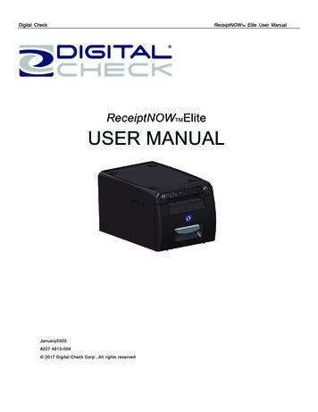
61234578 91Data cable (combined in same plug as power cable)2Transmit (output from this unit): TX A (yellow), TX B (blue)3Receive (input to this unit): RX A (orange), RX B (green)4Ground (shield)5Power cable612 V positive wire (red) shown with fuse holder installedinline712 V negative wire (black)8Not used (yellow)9Vessel’s 12 V DC supplyÚ Note: The majority of NMEA 0183 devices communicate at4,800 baud. AIS is a common exception, and normally transmitsat 38,400 baud.Talkers and ListenersDo not connect multiple devices outputting data (Talkers) on to anyserial input (RX) of the unit. The RS422 protocol is not intended forthis type of connection, and data will be corrupted if more than onedevice transmits simultaneously. The output (TX) however maydrive multiple receivers (Listeners). The number of receivers is finite,and depends on the receiving hardware. Typically three devices ispossible.Wiring ELITE Ti Installation Manual31
6Software SetupThis unit requires some initial configuration before use, in order toget the most out of the product. The following sections focus onsettings that typically do not require change once configured. Userpreference settings and operation are covered in the OperatorManual. Selecting the Home button opens the Home page, whichhas three distinct areas. The scrollable left column of icons is theTools panel. Select Settings in the Tools panel to open the Settingsdialog to access items that require configuration.First time startupWhen the unit is started for the first time, or after a factory default,the unit displays a setup wizard. Respond to the setup wizardprompts to select some fundamental setup options.You can perform further setup using the system settings option andlater change settings made with the setup wizard.Time and DateConfigure time settings to suit vessel location, along with time anddate formats.32Software Setup ELITE Ti Installation Manual
Data source selectionÚ Note: If NMEA 0183 is used, complete the NMEA 0183 setupprior to doing source selection. Refer to "NMEA 0183 setup" on page48.Data sources provide live data to the system.The data may originate from modules internal to the unit (forexample internal GPS or sonar), or external modules connected tothe NMEA 2000 or via NMEA 0183 if available on the unit.When a device is connected to more than one source providing thesame data, the user can choose the preferred source. Beforecommencing with source selection make sure all external devicesand the NMEA 2000 backbone are connected and are turned on.Device nameAssigning a name is useful in systems using more than one deviceof the same type and size. When viewing data sources or the devicelist, the assigned name will append the default product name virtual device function for easy identification.Auto configureAuto configure is not available on the ELITE-5Ti.The Auto configure option will look for all sources connected to thedevice. If more than one source is available for each data type,selection will be made from an internal priority list. This option willbe suitable for the majority of installations.Ú Note: Auto data source selection may already have beenselected at first time startup, however it should be redone if anynew devices have been added to the network since.Software Setup ELITE Ti Installation Manual33
Data sources - manual source selectionManual selection is generally only required where there is morethan one source for the same data, and the Auto configureselected source is not the one desired. Pressing the menu key whenthe desired source is highlighted provides additional options:Configure deviceConfigure device is not available on the ELITE-5Ti.Additional device options can be configured from both the Datasource menu or from the Device list. For further information, refer to"Device list" on page 35.ScopeScope is not available on the ELITE-5Ti.The active data source under any given category, can be set to beGlobal or Local.When a source is set as Global, it will be used by all displays on thenetwork.When a source is set as Local, it will only be used by the display thatselected it as the source.Ú Note: If changing a display from a Global source to a differentLocal source, change the Scope setting to Local before changingthe selected source, otherwise all other displays will bechanged over to the new source.Ú Note: Local and Global data settings apply to the selected datasource only. It is not possible to discretely set whether a datasource is Global or Local if it is not the active source on thedisplay being operated.Reset Global/LocalReset Global and Reset Local are not available on the ELITE-5Ti.Selecting Reset Global runs an Auto data source selection, andoverrides all previous manual source selections made on allnetworked devices.Selecting Reset Local reverts all data source selections on the unitbeing used to the Global source settings available from othernetworked units.34Software Setup ELITE Ti Installation Manual
Device listDevice list is not available on the ELITE-5Ti.The Device list shows the devices that provide data. This mayinclude a module inside the unit, or any external NMEA 2000 device.Selecting a device in this list will bring up additional details andactions:All dev
number 000-0127-49 (sold separately). This plug has two cables. One cable is for power and the other is for connecting to NMEA 0183 devices. The unit has a combined power and data - NMEA 0183 serial port, providing both an input and output for NMEA 0183 data. For connection location, refer to "Rear connections" on page 13.