Transcription
PRO ELITE PROFESSIONAL SERIESWATER TREATMENT SYSTEMSERVICE MANUAL
Table of ContentsPerformance Data Sheet (Arabic).3Performance Data Sheet.4How To Use This Manual.5Safety Information.5Valve Layout.6Demand Control Layout.6System Specifications 762.6Location Selection. 7Outdoor Locations. 7System Features.8Equipment Installation.9Water Line and Bypass Connections. 10Drain Line Connection.13Regenerant Line Connections.13Overflow Line Connection. 14Electrical Connection. 14System Operation.15Cycle Water Flows.15Camshaft Cycle Positions.16Valve Disc Location/Function.16Disinfection of Water Conditioning Systems.17Displays, Icons and Cursors.18Button Functions.18Programming Overview.19Demand Control Operation.19Level I Programming.19Level l Programming - Demand Conditioner.20Level II Programming – P Values.22Level I Programming – P Values.21Programming the Lockout Feature. 23Level lll Cycle Programming – C Values. 23Level IV Viewing History - H Values.24Program Reset.24Placing 268 Water Conditioning System Into Operation (Fill Brine Tank Last).25Refill First Operation.26Manual Regeneration Options. 27Pro Elite Valve - Exploded View and Parts List.28Conditioner Tank and Regenerant Tank Assembly - Exploded View and Parts List.30Brine Well Assembly - Exploded View and Parts List.32CH15675.32Troubleshooting. 33Troubleshooting (Arabic). 352 Pentair Pro Elite Professional Series Water Treatment System Service Manual
ﺟﺪول ﺑﻴﺎﻧﺎت اﻟﺘﺸﻐﻴﻞ و اﻷداء : ﺟﺪول ﺑﻴﺎﻧﺎت اﻟﺘﺸﻐﻴﻞ و اﻷداء ﻟﺠﻬﺎز Pro Elite ﻟﺘﻨﻘﻴﺔ اﻟﻤﻴﺎﻩ ﻣﻮدﻳﻞ Pro Elite 268-762-100-1044 Pro Elite 268-762-150-1248 Pro Elite 268-762-200-1248 ﻣﻌﺪل اﻟﺘﺪﻓﻖ اﻟﺘﺸﻐﻴﻠﻲ 8.00 ﺟﺎﻟﻮن / دﻗﻴﻘﺔ 13.00 ﺟﺎﻟﻮن / دﻗﻴﻘﺔ 15.00 ﺟﺎﻟﻮن / دﻗﻴﻘﺔ اﻧﺨﻔﺎض اﻟﻀﻐﻂ ﻋﻨﺪ ﻣﻌﺪل اﻟﺘﺪﻓﻖ اﻟﺘﺸﻐﻴﻠﻲ ﻣﻌﺪل اﻟﺴﻌﺔ )ﺟﺮﻳﻦ lb / ﻣﻠﺢ( Psi 5.5 Psi 9.5 Psi 14.4 13,309 @ 3.3 lbs 26,327 @ 9.0 lbs 31,682 @ 15.0 lbs 20,023 @ 4.95 lbs 39,609 @ 13.5 lbs 47,665 @ 22.5 lbs 28,548 @ 6.6 lbs 56,472 @ 18.0 lbs 67,958 @ 30.0 lbs 4,033 ﺟﺮﻳﻦ lbs 3.3 @ lb/ 4,045 ﺟﺮﻳﻦ lbs 4.95 @ lb/ 4,325 ﺟﺮﻳﻦ lbs 6.6 @ lb/ 5.5 ﺟﺎﻟﻮن / دﻗﻴﻘﺔ 5.5 ﺟﺎﻟﻮن / دﻗﻴﻘﺔ 1.5 ﻗﺪم ﻣﻜﻌﺐ 2.0 ﻗﺪم ﻣﻜﻌﺐ ” 12” x 48 ” 12” x 48 ﻣﻌﺪل اﻟﻐﺴﻴﻞ اﻟﻌﻜﺴﻲ 2.7 ﺟﺎﻟﻮن / دﻗﻴﻘﺔ 3.9 ﺟﺎﻟﻮن / دﻗﻴﻘﺔ 3.9 ﺟﺎﻟﻮن / دﻗﻴﻘﺔ ﻣﻌﺪل اﻟﺸﻄﻒ اﻟﺴﺮﻳﻊ 5.5 ﺟﺎﻟﻮن / دﻗﻴﻘﺔ 5.5 ﺟﺎﻟﻮن / دﻗﻴﻘﺔ 5.5 ﺟﺎﻟﻮن / دﻗﻴﻘﺔ ﻣﻌﺪل اﻟﻜﻔﺎءة ﻣﻌﺪل اﻟﺘﺪﻓﻖ اﻷﻗﺼﻰ ﺧﻼل ﻋﻤﻠﻴﺔ 5.5 ﺟﺎﻟﻮن / دﻗﻴﻘﺔ إﻋﺎدة اﻟﺘﻨﺸﻴﻂ 1.0 ﻗﺪم ﻣﻜﻌﺐ آﻤﻴﺔ اﻟﺮاﺗﻨﺞ ﻧﻮع Sybron C-249NS ﺣﺠﻢ اﻟﺘﻨﻚ ” 10” x 44 *اﻟﻀﻐﻂ اﻟﺘﺸﻐﻴﻠﻲ ، psi 125-20 اﻟﺤﺮارة اﻟﺘﺸﻐﻴﻠﻴﺔ C 38-1.7 *ﻧﻮع اﻟﻤﻠﺢ اﻟﻤﻔﻀﻞ اﺳﺘﻌﻤﺎﻟﻪ : آﻠﻮرﻳﺪ اﻟﺼﻮدﻳﻮم – ﺣﺒﻴﺒﺎت *ﺟﻤﻴﻊ اﻟﻤﻮدﻳﻼت اﻟﻤﺬآﻮرة أﻋﻼﻩ ﺗﻢ اﺧﺘﺒﺎرهﺎ ﻓﻲ اﻟﻈﺮوف اﻟﺘﺎﻟﻴﺔ : 35 psi 5 psi pH 7.5 0.5 اﻟﺘﺪﻓﻖ اﻟﺘﺠﺮﻳﺒﻲ %50 : ﻣﻦ ﻗﻴﻤﺔ اﻟﺘﺪﻓﻖ اﻟﺘﺸﻐﻴﻠﻲ Pentair Pro Elite Professional Series Water Treatment System Service Manual 3
Performance Data SheetPro Elite Demand Water Softener System Performance Data SheetModelPro Elite268-762-100-1044DemandPro Elite268-762-150-1248DemandPro 2 @ 3.3 lbs21,716 @ 9.0 lbs27,641 @ 15.0 lbs25,746 @ 4.95 lbs36,972 @ 13.5 lbs47,059 @ 22.5 lbs36,102 @ 6.6 lbs51,844 @ 18.0 lbs65,988 @ 30.0 lbsRated Efficiency(grains/lb Salt @ lb of salt)4,582 grains/lb @ 3.3 lbs5,201 grains/lb @ 4.95 lbs.5,470 grains/lb @ 6.6 lbsMaximum FLow RateDuring Regeneration (gpm)5.55.55.510% Cross Linked IonExchange Resin (cu ft)1.01.52.010" x 44"12" x 48"12" x 48"Backwash - GPM2.73.93.9Rapid Rinse/Purge - GPM5.55.55.5Rated Service Flow (gpm)Pressure Drop at RatedService Flow Rate (psi)Rated Capacity(grains @ lb of salt)Tank SizeOperating Pressure: 20-125 psi or 1.4-8.8 kg/cm2, Operating Temperature: 34-100 F or 1.1-43.3 CAcceptable Salt Type: Sodium Chloride - Pellet saltAll Systems above tested at 35 psi 5 psi, pH of 7.5 0.5, Capacity Testing Flow Rate 50% of the rated service flow rate for thevarious size systems.These water softener systems have been tested by WQA and conform to NSF/ANSI 44 for specificperformance claims as verified and substantiated by test data. The rated salt efficiencies above werealso determined in accordance with NSF/ANSI 44 and are only valid at the salt dosage referenced above.An efficiency rated water softener is a demand initiated regeneration (DIR) softener which also complieswith specific performance specifications intended to minimize the amount of regenerant brine and waterused in its operation. Efficiency rated water softeners shall have a rated salt efficiency of not less that3350 grains of total hardness exchanged per pound of salt (based on NaCl equivalency) (477 grams oftotal hardness exchanged per kilogram of salt), and shall not deliver more salt than its listed rating. Therated efficiency of the water softener, the salt dosage at that efficiency, the capacity at that salt dosageand that of the efficiency is only valid at the stated salt dosage. Efficiency is measured by a laboratorytest described in NSF/ANSI 44. The test represents the maximum possible efficiency the system canachieve. Operational efficiency is the actual efficiency achieved after the system has been installed. Itis typically less than the efficiency due to individual application factors including water hardness, waterusage, and other contaminants that reduce the water softener’s capacity. These systems are not intendedto be used for treating water that is microbiologically unsafe or of unknown quality without adequatedisinfection before or after the system. Refer to the system Installation and Service Manuals for set-upand programming instructions.Contact your local dealer for parts and service. See your owner’s manual for warranty informationPENTAIR Residential Filtration, LLC13845 Bishops Drive Suite 200Brookfield, WI 53005PHONE: (262) 238-44002/01/194 Pentair Pro Elite Professional Series Water Treatment System Service ManualTested and Certified byWQA against NSF/ANSIStd. 44 & 372 for “lead free”compliance & CSA B483.1.
How To Use This ManualThis installation manual is designed to guide the installerthrough the process of installing and starting water conditioningsystems featuring Pro Elite equipment.This manual is a reference and will not include every systeminstallation situation. The person installing this equipmentshould have: Training in the Pro Elite Demand systems. Knowledge of water conditioning and how to determineproper control settings. Adequate plumbing skills and qualifications per local andstate laws, codes, and ordinances.Icons That Appear In This ManualWARNING: Failure to follow thisinstruction can result in personal injuryor damage to the equipment.Note: Helpful hint to simplify procedure.Safety Information Observe all warnings that appear in this manual. Please review the entire Installation and Operation Manualbefore installing the water conditioning system. As with all plumbing projects, it is recommended thata trained professional water treatment dealer installthe water conditioning system. Please follow all localplumbing codes for installing this water conditioningsystem.WARNING: Excessive Weight Hazard.Use two or more people to move andinstall the conditioner. Failure to do socan result in injury (including back injury). System is not intended to be used for treating water thatis microbiologically unsafe or of unknown quality withoutadequate disinfection before or after the system. This water conditioning system is to be used only forpotable water. Inspect the water conditioning system for carriershortage or shipping damage before beginninginstallation. Use only lead-free solder and flux, as required by federaland state codes, when installing soldered copperplumbing. Use caution when installing soldered metal piping near thewater conditioning system. Heat can adversely affect theplastic control valve and bypass valve. Do not use petroleum-based lubricants such aspetroleum jelly, oils, or hydrocarbon-based lubricants.Use only 100% silicone lubricants. Use only the power transformer supplied with this waterconditioning system. All electrical connections must be completed accordingto local codes. The power outlet must be grounded.Install an appropriate grounding strap across the inlet and outletpiping of the water conditioning system to ensure that a properground is maintained.WARNING: Dry location use only, unlessused with a Listed Class 2 Power Supplysuitable for outdoor use. To disconnect power, unplug the AC adapter from itspower source. Observe drain line requirements. The drain line must bea minimum of 1/2-inch diameter. Use 3/4-inch pipe if thebackwash flow rate is greater than 5 gpm (19 Lpm) or thepipe length is greater than 20 feet (6 m). Do not support the weight of the system on the controlvalve fittings, plumbing, or the bypass. Do not allow this water conditioning system to freeze.Damage from freezing will void this water conditioningsystem’s warranty. Operating ambient temperature: 34 to 120 F(1 to 49 C). Operating water temperature: 35 to 100 F(1.7 to 38 C). Operating water pressure range : 20 to 125 psi(1.38 to 8.62 bar). In Canada the acceptable operatingwater pressure range is 20 to 100 psi(1.38 to 6.89 bar).WARNING: The valve and tankcomponents of this Pro Elite unit havebeen assembled and tightened to theproper factory torque specifications.Over tightening may result in impropervalve, probe and tank alignment and maydamage the tank O-ring (PN1010154). Keep the media tank in the upright position. Do not turnupside down or drop. Turning the tank upside down orlaying the tank on its side can cause media to enter thevalve. Ensure that all wiring and plumbing connections on themineral and brine tanks are installed correctly. Use only regenerants designed for water conditioning. Donot use ice melting salt, block salt or rock salt. All plastic connections should be hand tightened. plumbertape may be used on connections that do not use anO-ring seal. Do not use pipe dope type sealants on thevalve body. Do not use pliers or pipe wrenches.Pentair Pro Elite Professional Series Water Treatment System Service Manual 5
Valve LayoutOptical SensorOne Piece Valve Disc SpringValve DiscsCamshaftDemand ControlMotorOutletDrainRefill ControllerInjector and CapRegenerant Tube ConnectionInjector Screen FilterInletBackwash Drain ControlDemand Control LayoutAC Adapter Connection(12 Volt Input)SU MO TUWE TH FR SA DAYSTime/DayRegeneration Time/DayPMSalt AmountMotor & OpticalSensor ConnectionCapacityCheck SaltFrontBackDemand SeriesTurbine MeterInputSystem Specifications 762Model 1248Recharge StyleDemandDemandDemandMedia Tank Size10" x 44" (25 x 112 cm)12" x 48" (30.5 x 122 cm)12" x 48" (30.5 x 122 cm)1 ft (0.03 m )1.5 ft (0.04 m )2 ft3 (0.056 m3)19" x 36" (48.3 x 91.5 cm)19" x 36" (48.3 x 91.5 cm)19" x 36" (48.3 x 91.5 cm)240 lbs (109 kg)240 lbs (109 kg)240 lbs (109 kg)2.7 gpm (10.2 L/m)3.9 gpm (14.7 L/m)3.9 gpm (14.7 L/m)1" NPT1" NPT1" NPTDrain Connection Size3/4" NPT3/4" NPT3/4" NPTRecharge (Brine) ConnectionSize3/8" NPT3/8" NPT3/8" NPT21" x 42" x 72"(53.3 x 106.6 x 182.8 cm)21" x 42" x 72"(53.3 x 106.6 x 182.8 cm)21" x 42" x 72"(53.3 x 106.6 x 182.8 cm)140 lbs (63.5 kg)165 lbs (74.8 kg)200 lbs (90.7 kg)Resin VolumeRecharge (Salt) Tank SizeSalt StorageDrain Water RateService Connection SizeInstallation SpaceRequirementsShipping Weight336 Pentair Pro Elite Professional Series Water Treatment System Service Manual33
Location SelectionOutdoor LocationsLocation of a water conditioning system is important.The following conditions are required:It is recommended that the Pro Elite conditioner beinstalled in a protected environment. Level platform or floor.Note: The Pro Elite System can be provided withoptional leveling feet that may be used on the twotanks. Order part number 4000409. Room to access equipment for maintenanceand adding regenerant (salt) to tank. Ambient temperatures over 34 F(1 C and below 120 F (49 C). Water pressure below 125 psi (8.62bar) and above 20 psi (1.38 bar). In Canada the water pressure mustbe below 100 psi (6.89 bar). Constant electrical supply to operate the control. Total minimum pipe run to water heaterof ten feet (three meters) to preventbackup of hot water into system. Local drain for discharge as close as possible. Water line connections withshutoff or bypass valves. Must meet any local and statecodes for site of installation. Valve is designed for minor plumbingmisalignments. Do not support weightof system on the plumbing. Be sure all soldered pipes are fully cooled beforeattaching plastic valve to the plumbing.When installing the water conditioning system outdoors,several items must be considered: Moisture – The valve and control are ratedfor NEMA 3 locations. Falling water shouldnot affect performance. The system is notdesigned to withstand extreme humidityor water spray from below. Examplesare: constant heavy mist, near corrosiveenvironment, or upwards spray from sprinkler. Direct Sunlight – The materials used will fadeor discolor over time in direct sunlight. Theintegrity of the materials will not degrade tocause system failures. Temperature – Extreme hot or cold temperatureswill cause damage to the valve or control. Freezingtemperatures will freeze the water in the valve. Thiswill cause physical damage to the internal parts aswell as the plumbing and conditioning resin. Hightemperatures will affect the control. The displaymay become unreadable but the control shouldcontinue to function. When the temperature returnsto normal operating limits, the display will reappear. A protective cover should assist with hightemperature applications. Insects – The control and valve have been designedto keep all but the smallest insects out of thecritical areas. Any holes in the top plate can becovered with duct tape. The top cover should beinstalled securely in place.WARNING: Dry location use only, unlessused with a Listed Class 2 Power Supplysuitable for outdoor use.Pentair Pro Elite Professional Series Water Treatment System Service Manual 7
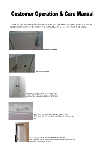
System FeaturesBrine TankResin Tank1128275137115331064124691Cover8Cover2Cap, Cover9Foot, Leveling3Jacket,Resin Tank10Latch Mechanism4Base11Tank Collar5268 Logix PE Valvew/762 Control12Riser Tube6Resin Tank13Upper Basket7Shield8 Pentair Pro Elite Professional Series Water Treatment System Service Manual1Cover5Brine Tube Assembly2Collar, Tank6Foot, Leveling3Tank, Brine7Latch Mechanism4Base, Tank
Equipment InstallationDimensions17.6 (447)16.8 (427.1)19.8 (503.8)20.5 (521.1)35.1 (890.4)5.0 (127)2.5 (63.5)55 (1398.1)60.7 (1541.6)53.4 (1356.6)32.2 (817.5)36.9 (938.1)28.2 (715.9)Pentair Pro Elite Professional Series Water Treatment System Service Manual 9
Typical System LayoutBath Tub Lavatory ToiletOutsideFaucetKitchenOutsideFaucetHot WaterOutletWaterHeaterLaundry TubsPumporMeterFloor DrainFigure 1 Standard Basement Before Installation. Cold water lines shown.Bath Tub Lavatory ToiletOutsideFaucetHot WaterOutletKitchenGroundingStrapSoft WaterHard WaterBypassDrain LineWaterHeaterSoftenerPumporMeterLaundry TubsBrine Tank Overflow DrainFloor DrainFigure 2 Softened Water Flow Diagram.10 Pentair Pro Elite Professional Series Water Treatment System Service ManualOutsideFaucet
InspectionTo Assemble the Media Tank:The Pro Elite system is shipped with several partsunassembled. When parts are removed from the packing,they should be inspected for damage. If any parts aredamaged or missing, contact your supplier.1. If the floor under the media tank is uneven, theleveling feet may be installed. Slowly lay the tank onits side. Press or tap the feet into the pockets.WARNING: The media tank containsloose particles that will shift. If thetank is turned upside down or laid backquickly, the particles may enter the valve.If this happens, the valve may need to bedisassembled and cleaned.WARNING: When handling the mediatank do not turn it upside down or dropon its side.When the carton is first opened, the softener will bestanding upright. The salt tank will be turned over andcovering the softener (Figure 3).Salt Tank CoverSalt Tank BaseSalt Tank Collar2. Stand the tank up and in position. Level as needed.3. Remove cover by pressing in on the latch and liftingcover (Figure 4). When the cover is removed, the valveis visible. Remove the power adapter. They shouldbe secured to the tank collar near the inlet/outletconnections.LiftPress inSalt Tank(Upside Down)Brine TubeAssemblyMedia Tank(Softener)Figure 4Media Tank BaseFigure 3To assemble the system, remove the salt tankcomponents (cover, collar, base and brine tube assembly)from the shipping container. The media tank can now beremoved. Locate the miscellaneous parts bag.To assemble the Salt Tank:1. If the floor under the salt tank is uneven, the levelingfeet may be installed. Lay the empty salt tank on itsside. Press or tap the feet into the pockets.2. Stand the salt tank up and in position. Levelas needed. The tank has two ports that will beconnected. One to a drain and one to the valve.3. Place the brine tube in position inside the pocket atthe bottom of the tank. Install the overflow fitting.4. Place the tank collar over the top of the brine tube.Position the collar and push it down into the tank. Laythe cover aside for now.Pentair Pro Elite Professional Series Water Treatment System Service Manual 11
Water Line and Bypass ConnectionsA bypass valve system should be installed on allwater conditioning systems. A model 1265 bypass isincluded with this system. The bypass valve isolatesthe conditioner from the water system and providesunconditioned water to service during routinemaintenance and servicing procedures. See Figure 5Model 1265 Bypass (Included) and Figure 6 Typical ThreeValve Bypass Configuration(Not provided by manufacturer).Note: Before turning on the water to the valve, rotatethe two handles on the bypass valve 2-3 times. This willhelp seat the O-rings and prevent leaking.Normal OperationOutInBYPA S SBYOutInIn BypassPA S SBYBYPA S SPA S SWater ConditionerWater ConditionerFigure 5 Model 1265 Bypass (Included)Normal OperationWater ConditionerIn BypassWater ConditionerFigure 6 Typical Three Valve Bypass ConfigurationWaterWater(Not provided by manufacturer)ConditionerConditioner12 Pentair Pro Elite Professional Series Water Treatment System Service ManualWARNING: Do not use tools to tightenplastic fittings. Over time, stress may breakthe connections. Hand tighten the nuts.WARNING: Do not use petroleum greaseon gaskets when connecting bypassplumbing. Use only 100% silicone greaseproducts when installing any Pro Elitebrand valve. Non-silicone grease maycause plastic components to fail overtime.WARNING: The inlet water must beconnected to the inlet port of the valve.When replacing non-Pro Elite valves,it is possible that the inlet and outletplumbing is installed in a reversedposition. Ensure that the plumbing isnot installed in the opposite order. Tankmedia may be pushed into the valve.
Drain Line ConnectionRegenerant Line ConnectionsThe regenerant line from the brine tank safety brine valve(Figure 11) connects to the valve. Make sure both safetyvalve tube fittings are tight. Make the connections andhand tighten.Note: Standard commercial practices are expressedhere. Local codes may require changes to the followingsuggestions. Check with local authorities beforeinstalling a water conditioning system.Note: Be sure that the regenerant line is secure and free1. The unit should be above and not more than 20 feet(6.1 m) from the drain. Use an appropriate adapterfitting to connect 1/2-inch (1.3 cm) plastic tubing tothe drain line connection of the control valve.from air leaks. Even a small leak may cause the regenerantline to drain out, and the conditioner will not draw regenerantfrom the tank. This may also introduce air into the valvecausing problems with valve operation.2. If the backwash flow rate exceeds 5 gpm (22.7 Lpm)or if the unit is located 20-40 feet (6.1 – 12.2 m) fromdrain, use 3/4-inch (1.9 cm) tubing. Use appropriatefittings to connect the 3/4-inch tubing to the 3/4-inchNPT drain connection on valve.Ensure that plumber tape pipe sealant is applied tothe 3/8-inch NPT regenerant line connection (Figure 1Standard Basement Before Installation. Cold water linesshown.)3. The drain line may be elevated up to 6 feet (1.8 m)provided the run does not exceed 15 feet (4.6 m) andwater pressure at the conditioner is not less than 40psi (2.76 bar). Elevation can increase by 2 feet (61 cm)for each additional 10-psi (.69 bar) of water pressureat the drain connector.4. When the drain line is elevated but empties into adrain below the level of the control valve, form a7-inch (18 cm) loop at the far end of the line so thatthe bottom of the loop is level with the drain lineconnection. This will provide an adequate siphon trap.Tie or wire the hose in place at the drain point. Alsoprovide an air gap of at least 1-1/2 inch between theend of the hose and the drain point.5. When the drain empties into an overhead sewer line, asink-type trap must be used.6. Secure the end of the drain line to prevent it frommoving.Regenerant Line ConnectionFigure 8Regenerant Line ConnectionTube FittingFigure 7 Drain Line ConnectionWARNING: Never insert drain line directlyinto a drain, sewer line or trap (Figure9). Always allow an air gap between thedrain line and the wastewater to preventthe possibility of sewage being backsiphoned into the conditioner.Figure 9 Salt Tank Safety Brine Valve andBrine Well AssemblyPentair Pro Elite Professional Series Water Treatment System Service Manual 13
Electrical ConnectionOverflow Line ConnectionIn the event of a malfunction, the regenerant tankoverflow will direct “overflow” to the drain instead ofspilling on the floor. This fitting should be on the side ofthe cabinet or regenerant tank, Figure 10.To connect the overflow line, locate the connection onside of the regenerant tank. Insert overflow fitting intotank and tighten with plastic thumbnut and gasket.Attach length of 1/2-inch (1.3 cm) I. D. tubing (not supplied)to fitting and run to drain. Do not elevate overflow linehigher than overflow fitting.Note: There are no user serviceable parts in the ACadapter, motor or the control board.The Demand control operates on a 12-volt alternatingcurrent power supply. This requires use of the PentairWater supplied AC adapter. AC adapters are availablefrom your supplier for different applications.They include:Do not tie into drain line of control unit. Overflow linemust be a direct, separate line from overflow fitting todrain, sewer or tub with an air gap at the drain.Regenerant Line OpeningOverflow FittingAC AdapterInput VoltageApplicationPart NumberStandardwall-mount230V, 50/60 Hzfor drylocations only1000813120V AC Adapters:Make sure power source matches the rating printed onthe AC adapter.Note: The power source should be constant. Be certainthe AC adapter is not on a switched outlet. Powerinterruptions longer than eight hours may cause thecontrol to lose the day and time settings. When poweris restored, the control will display four dashes (- - :- -)indicating that the day and time settings must bere-entered.Drain TubingSecure hose in placeDrainAir GapFigure 1014 Pentair Pro Elite Professional Series Water Treatment System Service Manual
System OperationRepressurization – Cycle C4Treated Water (Downflow)Pressure is balanced in the valve before continuing theregeneration.Untreated water is conditioned as it flows through theresin bed and up the riser.Fast Rinse (Downflow) - Cycle C5Water passes through the resin bed and up through theriser to drain. All remaining regenerant residual is rinsedfrom the resin bed.If the model selected at first start-up was 268r, thisis a system that will refill the salt tank at the start of aregeneration cycle. When a regeneration cycle begins,the salt tank is filled and brine is allowed to developbefore Cycle 1 starts.2nd Backwash (Upflow) – Cycle C6Flow is identical to C1 Backwash. The resin is reclassified.Backwash (Upflow) – Cycle C1Flow is reversed by the control valve, directed down theriser, up through the resin bed and sent to drain. The bedis expanded and debris is flushed to the drain.2nd Rinse (Downflow) - Cycle C7Regenerant Draw (Downflow) – Cycle C2*Regenerant Refill Last – Cycle C8Water passes through the injector and regenerant isdrawn from the regenerant tank. The regenerant isdirected to the resin bed. The hardness ions are displacedby sodium ions. Regenerant draw is completed when theair check closes.Refill last only occurs if the model s
Pro Elite Demand Water Softener System Performance Data Sheet Model Pro Elite 268-762-100-1044 Demand Pro Elite 268-762-150-1248 Demand Pro Elite 268-762-200-1248 Demand Rated Service Flow (gpm) 12.0 13.0 14.4 Pressure Drop at Rated Service Flow Rate (psi) 11 12 15 Rated Capacity (grains @ lb of salt) Rated Efficiency (grains/lb Salt @ lb of salt)