Transcription
PRO ELITE PROFESSIONAL SERIESPRO ELITE ANALYZER WATER TREATMENT SYSTEM BY PENTAIROPERATION MANUAL
TABLE OF CONTENTSPerformance Data Sheet . . . . . . . . . . . . . . . . . . . . . . . . . . . . . . . . . . . . . . . . . . . . . . . . . . . . . . . . . . . . . . . . . . . . . . . . . . . . . . . . . . . . . . . . . . . . . . . . . . 3How To Use This Manual. . . . . . . . . . . . . . . . . . . . . . . . . . . . . . . . . . . . . . . . . . . . . . . . . . . . . . . . . . . . . . . . . . . . . . . . . . . . . . . . . . . . . . . . . . . . . . . . . . . 4Safety Information. . . . . . . . . . . . . . . . . . . . . . . . . . . . . . . . . . . . . . . . . . . . . . . . . . . . . . . . . . . . . . . . . . . . . . . . . . . . . . . . . . . . . . . . . . . . . . . . . . . . . . . . 4Valve Layout . . . . . . . . . . . . . . . . . . . . . . . . . . . . . . . . . . . . . . . . . . . . . . . . . . . . . . . . . . . . . . . . . . . . . . . . . . . . . . . . . . . . . . . . . . . . . . . . . . . . . . . . . . . . . 5Analyzer Control Layout. . . . . . . . . . . . . . . . . . . . . . . . . . . . . . . . . . . . . . . . . . . . . . . . . . . . . . . . . . . . . . . . . . . . . . . . . . . . . . . . . . . . . . . . . . . . . . . . . . . 5System Specifications 716. . . . . . . . . . . . . . . . . . . . . . . . . . . . . . . . . . . . . . . . . . . . . . . . . . . . . . . . . . . . . . . . . . . . . . . . . . . . . . . . . . . . . . . . . . . . . . . . . 5Location Selection . . . . . . . . . . . . . . . . . . . . . . . . . . . . . . . . . . . . . . . . . . . . . . . . . . . . . . . . . . . . . . . . . . . . . . . . . . . . . . . . . . . . . . . . . . . . . . . . . . . . . . . 6Outdoor Locations. . . . . . . . . . . . . . . . . . . . . . . . . . . . . . . . . . . . . . . . . . . . . . . . . . . . . . . . . . . . . . . . . . . . . . . . . . . . . . . . . . . . . . . . . . . . . . . . . . . . . . . . 6System Features . . . . . . . . . . . . . . . . . . . . . . . . . . . . . . . . . . . . . . . . . . . . . . . . . . . . . . . . . . . . . . . . . . . . . . . . . . . . . . . . . . . . . . . . . . . . . . . . . . . . . . . . . 7Equipment Installation. . . . . . . . . . . . . . . . . . . . . . . . . . . . . . . . . . . . . . . . . . . . . . . . . . . . . . . . . . . . . . . . . . . . . . . . . . . . . . . . . . . . . . . . . . . . . . . . . . . . 8Water Line and Bypass Connections. . . . . . . . . . . . . . . . . . . . . . . . . . . . . . . . . . . . . . . . . . . . . . . . . . . . . . . . . . . . . . . . . . . . . . . . . . . . . . . . . . . . . . . 11Drain Line Connection . . . . . . . . . . . . . . . . . . . . . . . . . . . . . . . . . . . . . . . . . . . . . . . . . . . . . . . . . . . . . . . . . . . . . . . . . . . . . . . . . . . . . . . . . . . . . . . . . . . 12Regenerant Line Connections. . . . . . . . . . . . . . . . . . . . . . . . . . . . . . . . . . . . . . . . . . . . . . . . . . . . . . . . . . . . . . . . . . . . . . . . . . . . . . . . . . . . . . . . . . . . 12Overflow Line Connection. . . . . . . . . . . . . . . . . . . . . . . . . . . . . . . . . . . . . . . . . . . . . . . . . . . . . . . . . . . . . . . . . . . . . . . . . . . . . . . . . . . . . . . . . . . . . . . . 13Electrical Connection. . . . . . . . . . . . . . . . . . . . . . . . . . . . . . . . . . . . . . . . . . . . . . . . . . . . . . . . . . . . . . . . . . . . . . . . . . . . . . . . . . . . . . . . . . . . . . . . . . . . 13System Operation . . . . . . . . . . . . . . . . . . . . . . . . . . . . . . . . . . . . . . . . . . . . . . . . . . . . . . . . . . . . . . . . . . . . . . . . . . . . . . . . . . . . . . . . . . . . . . . . . . . . . . . 14Cycle Water Flows . . . . . . . . . . . . . . . . . . . . . . . . . . . . . . . . . . . . . . . . . . . . . . . . . . . . . . . . . . . . . . . . . . . . . . . . . . . . . . . . . . . . . . . . . . . . . . . . . . . . . . . 14Camshaft Cycle Positions . . . . . . . . . . . . . . . . . . . . . . . . . . . . . . . . . . . . . . . . . . . . . . . . . . . . . . . . . . . . . . . . . . . . . . . . . . . . . . . . . . . . . . . . . . . . . . . . 15Valve Disc Location/Function. . . . . . . . . . . . . . . . . . . . . . . . . . . . . . . . . . . . . . . . . . . . . . . . . . . . . . . . . . . . . . . . . . . . . . . . . . . . . . . . . . . . . . . . . . . . . 15Disinfection of Water Conditioning Systems . . . . . . . . . . . . . . . . . . . . . . . . . . . . . . . . . . . . . . . . . . . . . . . . . . . . . . . . . . . . . . . . . . . . . . . . . . . . . . . . 16Displays, Icons and Cursors. . . . . . . . . . . . . . . . . . . . . . . . . . . . . . . . . . . . . . . . . . . . . . . . . . . . . . . . . . . . . . . . . . . . . . . . . . . . . . . . . . . . . . . . . . . . . . . 17Button Functions. . . . . . . . . . . . . . . . . . . . . . . . . . . . . . . . . . . . . . . . . . . . . . . . . . . . . . . . . . . . . . . . . . . . . . . . . . . . . . . . . . . . . . . . . . . . . . . . . . . . . . . . 17Programming Overview . . . . . . . . . . . . . . . . . . . . . . . . . . . . . . . . . . . . . . . . . . . . . . . . . . . . . . . . . . . . . . . . . . . . . . . . . . . . . . . . . . . . . . . . . . . . . . . . . . 18Analyzer Control Operation. . . . . . . . . . . . . . . . . . . . . . . . . . . . . . . . . . . . . . . . . . . . . . . . . . . . . . . . . . . . . . . . . . . . . . . . . . . . . . . . . . . . . . . . . . . . . . . 18Level I Programming. . . . . . . . . . . . . . . . . . . . . . . . . . . . . . . . . . . . . . . . . . . . . . . . . . . . . . . . . . . . . . . . . . . . . . . . . . . . . . . . . . . . . . . . . . . . . . . . . . . . . 18Level l Programming - Analyzer Conditioner. . . . . . . . . . . . . . . . . . . . . . . . . . . . . . . . . . . . . . . . . . . . . . . . . . . . . . . . . . . . . . . . . . . . . . . . . . . . . . . . 19Level II Programming – P Values . . . . . . . . . . . . . . . . . . . . . . . . . . . . . . . . . . . . . . . . . . . . . . . . . . . . . . . . . . . . . . . . . . . . . . . . . . . . . . . . . . . . . . . . . . 20Programming the Lockout Feature . . . . . . . . . . . . . . . . . . . . . . . . . . . . . . . . . . . . . . . . . . . . . . . . . . . . . . . . . . . . . . . . . . . . . . . . . . . . . . . . . . . . . . . . 20Level lll Cycle Programming – C Values. . . . . . . . . . . . . . . . . . . . . . . . . . . . . . . . . . . . . . . . . . . . . . . . . . . . . . . . . . . . . . . . . . . . . . . . . . . . . . . . . . . . . 21Level IV Viewing History - H Values . . . . . . . . . . . . . . . . . . . . . . . . . . . . . . . . . . . . . . . . . . . . . . . . . . . . . . . . . . . . . . . . . . . . . . . . . . . . . . . . . . . . . . . . 22Program Reset. . . . . . . . . . . . . . . . . . . . . . . . . . . . . . . . . . . . . . . . . . . . . . . . . . . . . . . . . . . . . . . . . . . . . . . . . . . . . . . . . . . . . . . . . . . . . . . . . . . . . . . . . . 22Placing 268 Water Conditioning System Into Operation (Fill Brine Tank Last). . . . . . . . . . . . . . . . . . . . . . . . . . . . . . . . . . . . . . . . . . . . . . . . . . . . 23Placing 268r Water Conditioning System Into Operation (Fill Brine Tank First). . . . . . . . . . . . . . . . . . . . . . . . . . . . . . . . . . . . . . . . . . . . . . . . . . . 24The Water Conditioning System is Now Fully Operational. . . . . . . . . . . . . . . . . . . . . . . . . . . . . . . . . . . . . . . . . . . . . . . . . . . . . . . . . . . . . . . . . . . . . 25Manual Regeneration Options. . . . . . . . . . . . . . . . . . . . . . . . . . . . . . . . . . . . . . . . . . . . . . . . . . . . . . . . . . . . . . . . . . . . . . . . . . . . . . . . . . . . . . . . . . . . . 25Pro Elite Valve - Exploded View and Parts List. . . . . . . . . . . . . . . . . . . . . . . . . . . . . . . . . . . . . . . . . . . . . . . . . . . . . . . . . . . . . . . . . . . . . . . . . . . . . . . 26Conditioner Tank and Regenerant Tank Assembly - Exploded View and Parts List. . . . . . . . . . . . . . . . . . . . . . . . . . . . . . . . . . . . . . . . . . . . . . . 28Brine Well Assembly - Exploded View and Parts List . . . . . . . . . . . . . . . . . . . . . . . . . . . . . . . . . . . . . . . . . . . . . . . . . . . . . . . . . . . . . . . . . . . . . . . . . 30Troubleshooting. . . . . . . . . . . . . . . . . . . . . . . . . . . . . . . . . . . . . . . . . . . . . . . . . . . . . . . . . . . . . . . . . . . . . . . . . . . . . . . . . . . . . . . . . . . . . . . . . . . . . . . . . 312 PENTAIR Pro Elite Professional Series Pro Elite Analyzer Instruction Manual
PERFORMANCE DATA SHEETPro Elite Analyzer Water Softener System Performance Data SheetModelPro ElitePE-26-01 AnalyzerPro ElitePE-40-01 AnalyzerPro ElitePE-60-01 Analyzer12.013.014.411121515,122 @ 3.3 lbs21,716 @ 9.0 lbs27,641 @ 15.0 lbs25,746 @ 4.95 lbs36,972 @ 13.5 lbs47,059 @ 22.5 lbs36,102 @ 6.6 lbs51,844 @ 18.0 lbs65,988 @ 30.0 lbsRated Efficiency(grains/lb Salt @ lb of salt)4,582 /lb. salt @ 3.3 lbs5,201/lb. salt @ 4.95 lbs5,470/lb. salt @ 6.6 lbsMaximum FLow RateDuring Regeneration (gpm)5.55.55.510% Cross Linked IonExchange Resin (cu ft)1.01.52.010" x 44"12" x 48"12" x 48"Backwash - GPM2.73.93.9Rapid Rinse/Purge - GPM5.55.55.5Rated Service Flow (gpm)Pressure Drop at RatedService Flow Rate (psi)Rated Capacity(grains @ lb of salt)Tank SizeOperating Pressure:20 -125 psi or 1.4 – 8.8 kg/Centimeter2, Operating Temperature: 34 - 100 F or 1.1 – 38 CAcceptable Salt Type: Sodium Chloride – Pellet or solar salt water softenersAll Systems above tested at 35psi /- 5 psi, pH of 7.5 /- 0.5, Capacity Testing Flow Rate 50% of the rated service flow rate for thevarious size systems.These water softener systems have been tested by WQA and conform to NSF/ANSI 44 for specific performanceclaims as verified and substantiated by test data. The rated salt efficiencies above were also determined inaccordance with NSF/ANSI 44 and are only valid at the salt dosage referenced above. An efficiency rated watersoftener is a demand initiated regeneration (DIR) softener which also complies with specific performancespecifications intended to minimize the amount of regenerant brine and water used in its operation.Efficiency rated water softeners shall have a rated salt efficiency of not less that 3350 grains of total hardnessexchanged per pound of salt (based on NaCl equivalency) (477 grams of total hardness exchanged per kilogramof salt), and shall not deliver more salt than its listed rating. The rated efficiency of the water softener, the saltdosage at that efficiency, the capacity at that salt dosage and that of the efficiency is only valid at the statedsalt dosage. Efficiency is measured by a laboratory test described in NSF/ANSI 44. The test represents themaximum possible efficiency the system can achieve. Operational efficiency is the actual efficiency achievedafter the system has been installed. It is typically less than the efficiency due to individual application factorsincluding water hardness, water usage, and other contaminants that reduce the water softener’s capacity.These systems are not intended to be used for treating water that is microbiologically unsafe or of unknownquality without adequate disinfection before or after the system. Refer to the system Installation and ServiceManuals for set-up and programming instructions.Tested and Certified by WQAagainst NSF/ANSI Std. 44 &372 for “lead free” compliance& CSA B483.1.Contact your local dealer for parts and service. See your owner’s manual for warrant informationPENTAIR Residential Filtration, LLC13845 Bishops Drive Suite 200Brookfield, WI 53005PHONE: (262) 238-440002/01/19PENTAIR Pro Elite Professional Series Pro Elite Analyzer Instruction Manual 3
Use only the power transformer supplied with this waterconditioning system.HOW TO USE THIS MANUALThis installation manual is designed to guide the installer throughthe process of installing and starting water conditioning systemsfeaturing Pro Elite equipment.This manual is a reference and will not include every systeminstallation situation. The person installing this equipment shouldhave: Training in the Pro Elite Demand systems. Knowledge of water conditioning and how to determineproper control settings. Adequate plumbing skills and qualifications per local andstate laws, codes, and ordinances. All electrical connections must be completed according tolocal codes. The power outlet must be grounded.Install an appropriate grounding strap across the inlet and outletpiping of the water conditioning system to ensure that a properground is maintained.WARNING: Dry location use only, unlessused with a Listed Class 2 Power Supplysuitable for outdoor use. To disconnect power, unplug the AC adapter from its powersource.Icons That Appear In This Manual Observe drain line requirements. The drain line must bea minimum of 1/2-inch diameter. Use 3/4-inch pipe if thebackwash flow rate is greater than 5 gpm (19 Lpm) or thepipe length is greater than 20 feet (6 m).WARNING: Failure to follow thisinstruction can result in personal injuryor damage to the equipment. Do not support the weight of the system on the control valvefittings, plumbing, or the bypass.Note: Note: Helpful hint to simplify procedure. Do not allow this water conditioning system to freeze.Damage from freezing will void this water conditioningsystem’s warranty.SAFETY INFORMATION Observe all warnings that appear in this manual. Operating ambient temperature: 34 to 120 F(1 to 49 C). Please review the entire Installation and Operation Manualbefore installing the water conditioning system. Operating water temperature: 35 to 100 F(1.7 to 38 C). As with all plumbing projects, it is recommended that atrained professional water treatment dealer install the waterconditioning system. Please follow all local plumbing codesfor installing this water conditioning system. Operating water pressure range : 20 to 125 psi(1.38 to 8.62 bar). In Canada the acceptable operating waterpressure range is 20 to 100 psi(1.38 to 6.89 bar).WARNING: Excessive Weight Hazard.Use two or more people to move andinstall the conditioner. Failure to do socan result in injury (including back injury).WARNING: The valve and tankcomponents of this Pro Elite unit havebeen assembled and tightened to theproper factory torque specifications.Over tightening may result in impropervalve, probe and tank alignment and maydamage the tank O-ring (PN1010154). System is not intended to be used for treating water thatis microbiologically unsafe or of unknown quality withoutadequate disinfection before or after the system. This water conditioning system is to be used only for potablewater. Inspect the water conditioning system for carrier shortageor shipping damage before beginning installation. Keep the media tank in the upright position. Do not turnupside down or drop. Turning the tank upside down or layingthe tank on its side can cause media to enter the valve. Use only lead-free solder and flux, as required by federal andstate codes, when installing soldered copper plumbing. Ensure that all wiring and plumbing connections on themineral and brine tanks are installed correctly. Use caution when installing soldered metal piping near thewater conditioning system. Heat can adversely affect theplastic control valve and bypass valve.Use only regenerants designed for water conditioning. Do not useice melting salt, block salt or rock salt. All plastic connections should be hand tightened. plumbertape may be used on connections that do not use an O-ringseal. Do not use pipe dope type sealants on the valve body.Do not use pliers or pipe wrenches. Do not use petroleum-based lubricants such as Vaseline,oils, or hydrocarbon-based lubricants. Use only 100%silicone lubricants.4 PENTAIR Pro Elite Professional Series Pro Elite Analyzer Instruction Manual
VALVE LAYOUTOptical SensorOne Piece Valve Disc SpringValve DiscsCamshaftAnalyzer ControlMotorOutletDrainRefill ControllerInjector and CapRegenerant Tube ConnectionInjector Screen FilterInletBackwash Drain ControlANALYZER CONTROL LAYOUTAC Adapter Connection(12 Volt Input)SU MO TUWE TH FR SA DAYSTime/DayRegeneration Time/DayPMSalt AmountMotor & OpticalSensor ConnectionCapacityCheck SaltAnalyzer ProbeConnectionSYSTEM SPECIFICATIONS 716Model NumberPE-26-01PE-40-01PE-60-01Recharge StyleAnalyzerAnalyzerAnalyzerMedia Tank Size10" x 44" (25 x 112 cm)12" x 48" (30.5 x 122 cm)12" x 48" (30.5 x 122 cm)1 ft3 (0.03 m3)1.5 ft3 (0.04 m3)2 ft3 (0.056 m3)19" x 36" (48.3 x 91.5 cm)19" x 36" (48.3 x 91.5 cm)19" x 36" (48.3 x 91.5 cm)240 lbs (109 kg)240 lbs (109 kg)240 lbs (109 kg)2.7 gpm (10.2 L/m)3.9 gpm (14.7 L/m)3.9 gpm (14.7 L/m)1" NPT1" NPT1" NPTDrain Connection Size3/4" NPT3/4" NPT3/4" NPTRecharge (Brine) ConnectionSize3/8" NPT3/8" NPT3/8" NPT21" x 42" x 72"(53.3 x 106.6 x 182.8 cm)21" x 42" x 72"(53.3 x 106.6 x 182.8 cm)21" x 42" x 72"(53.3 x 106.6 x 182.8 cm)140 lbs (63.5 kg)165 lbs (74.8 kg)200 lbs (90.7 kg)Resin VolumeRecharge (Salt) Tank SizeSalt StorageDrain Water RateService Connection SizeInstallation SpaceRequirementsShipping WeightPENTAIR Pro Elite Professional Series Pro Elite Analyzer Instruction Manual 5
LOCATION SELECTIONOUTDOOR LOCATIONSLocation of a water conditioning system is important. Thefollowing conditions are required: Level platform or floor.It is recommended that the Pro Elite conditioner be installed in aprotected environment.When installing the water conditioning system outdoors, severalitems must be considered: Moisture – The valve and control are rated for NEMA 3locations. Falling water should not affect performance.The system is not designed to withstand extreme humidityor water spray from below. Examples are: constant heavymist, near corrosive environment, or upwards spray fromsprinkler. Ensure that the Analyzer probe access panel isinstalled on the unit. Direct Sunlight – The materials used will fade or discolorover time in direct sunlight. The integrity of the materialswill not degrade to cause system failures. Temperature – Extreme hot or cold temperatures will causedamage to the valve or control. Freezing temperatureswill freeze the water in the valve. This will cause physicaldamage to the internal parts as well as the plumbing andconditioning resin. High temperatures will affect thecontrol. The display may become unreadable but the controlshould continue to function. When the temperature returnsto normal operating limits, the display will re-appear. Aprotective cover should assist with high temperatureapplications. Insects – The control and valve have been designed to keepall but the smallest insects out of the critical areas. Anyholes in the top plate can be covered with duct tape. The topcover should be installed securely in place.Note: The Pro Elite System can be provided with optionalleveling feet that may be used on the two tanks. Orderpart number 4000409. Room to access equipment for maintenance and addingregenerant (salt) to tank. Ambient temperatures over 34 F (1 C and below 120 F(49 C). Water pressure below 125 psi (8.62 bar) and above 20 psi(1.38 bar). In Canada the water pressure must be below 100 psi (6.89bar). Constant electrical supply to operate the control. Total minimum pipe run to water heater of ten feet (threemeters) to prevent backup of hot water into system. Local drain for discharge as close as possible. Water line connections with shutoff or bypass valves. Must meet any local and state codes for site of installation. Valve is designed for minor plumbing misalignments. Do notsupport weight of system on the plumbing. Be sure all soldered pipes are fully cooled before attachingplastic valve to the plumbing.WARNING: Dry location use only, unlessused with a Listed Class 2 Power Supplysuitable for outdoor use.6 PENTAIR Pro Elite Professional Series Pro Elite Analyzer Instruction Manual
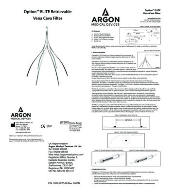
SYSTEM FEATURESBrine TankResin Tank121142513117853310761244961Cover9Foot, Leveling1Cover5Brine Tube Assembly2Cap, Cover10Latch Mechanism2Collar, Tank6Foot, Leveling3Jacket,Resin Tank11Tank Collar3Tank, Brine7Latch Mechanism4Base12Riser Tube4Base, Tank5268 Logix PE Valvew/716 Control13Upper Basket6Resin Tank14Cover7Door, Access, Sensor8Sensors WiredProbesPENTAIR Pro Elite Professional Series Pro Elite Analyzer Instruction Manual 7
EQUIPMENT INSTALLATIONDimensions5.0 (127)2.5 (63.5)55 (1398.1)60.7 (1541.6)53.4 (1356.6)32.2 (817.5)36.9 (938.1)28.2 (715.9)8 PENTAIR Pro Elite Professional Series Pro Elite Analyzer Instruction Manual
Typical System LayoutBath Tub Lavatory ToiletOutsideFaucetKitchenOutsideFaucetHot WaterOutletWaterHeaterLaundry TubsPumporMeterFloor DrainFigure 1. Standard Basement Before Installation. Cold water lines shown.Bath Tub Lavatory ToiletOutsideFaucetHot WaterOutletKitchenGroundingStrapSoft WaterOutsideFaucetHard WaterBypassDrain LineWaterHeaterSoftenerPumporMeterLaundry TubsBrine Tank Overflow DrainFloor DrainFigure 2. Softened Water Flow Diagram.PENTAIR Pro Elite Professional Series Pro Elite Analyzer Instruction Manual 9
InspectionTo Assemble the Media Tank:The Pro Elite system is shipped with several parts unassembled.When parts are removed from the packing, they should beinspected for damage. If any parts are damaged or missing,contact your supplier.1. If the floor under the media tank is uneven, the leveling feetmay be installed. Slowly lay the tank on its side. Press or tapthe feet into the pockets.WARNING: The media tank containsloose particles that will shift. If thetank is turned upside down or laid backquickly, the particles may enter the valve.If this happens, the valve may need to bedisassembled and cleaned.WARNING: When handling the media tankdo not turn it upside down or drop on itsside.When the carton is first opened, the softener will be standingupright. The salt tank will be turned over and covering thesoftener (“Figure 3.”).Salt Tank CoverSalt TankBaseSalt Tank Collar2. Stand the tank up and in position. Level as needed.3. Remove cover by pressing in on the latch and lifting cover(“Figure 4.”). When the cover is removed, the valve is visible.Remove the power adapter. They should be secured to thetank collar near the inlet/outlet connections.LiftPressinSalt Tank(Upside Down)Figure 4.Brine TubeAssemblyMedia Tank(Softener)Media Tank BaseFigure 3.To assemble the system, remove the salt tank components (cover,collar, base and brine tube assembly) from the shipping container.The media tank can now be removed. Locate the miscellaneousparts bag.To assemble the Salt Tank:1. If the floor under the salt tank is uneven, the leveling feet maybe installed. Lay the empty salt tank on its side. Press or tapthe feet into the pockets.2. Stand the salt tank up and in position. Level as needed. Thetank has two ports that will be connected. One to a drain andone to the valve.3. Place the brine tube in position inside the pocket at thebottom of the tank. Install the overflow fitting.4. Place the tank collar over the top of the brine tube. Positionthe collar and push it down into the tank. Lay the cover asidefor now.Tank and Probe AssemblyThe probes are preinstalled to the media tank. The probesare located behind an access panel on the jacket of the mediatank. To remove the access panel, remove the four screws andwashers.Use only 100% silicone lubricant on the probe O-rings (“Figure 5.”).Do not allow the lubricant to come into contact with the probepins. Install the probe assemblies into the tank and secure withthe locking clasp (“Figure 6.”).Important: The pins on the probes will only fit into thebulkhead fittings one way. The pins must go into thematching holes at the bottom of the fitting. The probe withthe shortest length of wire must be on top.Install the protective shield (“Figure 6.” ).Note: Do not attempt to tighten or loosen the Bulkhead10 PENTAIR Pro Elite Professional Series Pro Elite Analyzer Instruction Manualfittings, as they are secured with a locking adhesive.
Normal OperationO-ringIn BypassProbeProbe PinsLubricateFigure 5.Water ConditionerBulkheadFittingLocking ClaspWater ConditionerFigure 8. Typical Three Valve Bypass ConfigurationWaterWater(Not provided by manufacturer)ConditionerConditionerWARNING: Do not use tools to tightenplastic fittings. Over time, stress maybreak the connections. Hand tighten thenuts.Figure 6.WATER LINE AND BYPASS CONNECTIONSA bypass valve system should be installed on all waterconditioning systems. A model 1265 bypass is included with thissystem. The bypass valve isolates the conditioner from the watersystem and provides unconditioned water to service duringroutine maintenance and servicing procedures. See “Figure 7.Model 1265 Bypass (Included)” and “Figure 8. Typical Three ValveBypass Configuration(Not provided by manufacturer)”.Note: Before turning on the water to the valve, rotate thetwo handles on the bypass valve 2-3 times. This willhelp seat the O-rings and prevent leaking.Normal OperationOutPA S SInWARNING: The inlet water must beconnected to the inlet port of the valve.When replacing non-Pro Elite valves,it is possible that the inlet and outletplumbing is installed in a reversedposition. Ensure that the plumbing isnot installed in the opposite order. Tankmedia may be pushed into the valve.BYBYOutInIn BypassWARNING: Do not use petroleum greaseon gaskets when connecting bypassplumbing. Use only 100% silicone greaseproducts when installing any Pro Elitebrand valve. Non-silicone grease maycause plastic components to fail overtime.PA S SBYBYPA S SPA S SWater ConditionerWater ConditionerFigure 7. Model 1265 Bypass (Included)PENTAIR Pro Elite Professional Series Pro Elite Analyzer Instruction Manual 11
DRAIN LINE CONNECTIONNote: Standard commercial practices are expressed here.Local codes may require changes to the followingsuggestions. Check with local authorities beforeinstalling a water conditioning system.1. The unit should be above and not more than 20 feet (6.1 m)from the drain. Use an appropriate adapter fitting to connect1/2-inch (1.3 cm) plastic tubing to the drain line connection ofthe control valve.2. If the backwash flow rate exceeds 5 gpm (22.7 Lpm) or if theunit is located 20-40 feet (6.1 – 12.2 m) from drain, use 3/4-inch(1.9 cm) tubing. Use appropriate fittings to connect the 3/4inch tubing to the 3/4-inch NPT drain connection on valve.3. The drain line may be elevated up to 6 feet (1.8 m) providedthe run does not exceed 15 feet (4.6 m) and water pressure atthe conditioner is not less than 40 psi (2.7
Pro Elite Analyzer Water Softener System Performance Data Sheet Model Pro Elite PE-26-01 Analyzer Pro Elite PE-40-01 Analyzer Pro Elite PE-60-01 Analyzer Rated Service Flow (gpm) 12.0 13.0 14.4 Pressure Drop at Rated Service Flow Rate (psi) 11 12 15 Rated Capacity (grains @ lb of salt)