Transcription
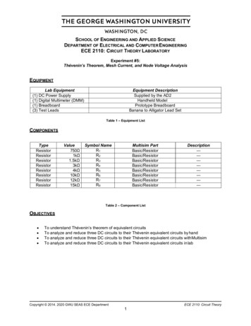
Principles of Electrical Engineering Lab 1Multisim ManualMultisim is the schematic capture and simulation application of National Instruments Circuit Design Suite,a suite of EDA (Electronic Design Automation) tools. It is similar to PSpice, but it is more easy to use inpractical sense and has lots of features to make circuit drawing/simulating, a really simple task. Here iswindow of multisim, as it appears first time when you start the software.23456798112Multisim1110Page 1
Principles of Electrical Engineering Lab 11. The Menu Bar is where you find commands for all functions.2. The Design Toolbox lets you navigate through the different types of files in a project (schematics,PCBs, reports), view a schematic’s hierarchy and show or hide different layers.3. The Component toolbar contains buttons that let you select components from the Multisimdatabases for placement in your schematic.4. The Standard toolbar contains buttons for commonly-performed functions such as Save, Print, Cut,and Paste.5. The View toolbar contains buttons for modifying the way the screen is displayed.6. The Simulation toolbar contains buttons for starting, stopping, and other simulation functions.7. The Main toolbar contains buttons for common Multisim functions.8. The In Use List contains a list of all components used in the design.9. The Instruments toolbar contains buttons for each instrument.10. Scroll Left –right is to ensure ease in handling larger designs.11. The Circuit Window (or workspace) is where you build your circuit.12. Active tab indicates the current active circuit window.Let’s take an example of a RC circuit. We will simulate the circuit to perform the transient analysis. At anypoint of time you can click F1 for help on the tool.Please follow the steps:1. Select Start»All Programs» National Instruments» Circuit Design Suite 10.1» Multisim 10.1. Ablank file opens on the workspace called Circuit1.2. Select File» Save As to display a standard Windows Save dialog.3. Select Place» Component to display the Select a Component browser, navigate to the groupSources and click on POWER SOURCES. Then choose the Family: AC POWER option. Thecomponent appears as a “ghost” on the cursor. (Once you have selected the desired Group andFamily, start typing the component’s name in the browser’s Component field. As you type, the stringappears in the Searching field at the bottom of the browser.)MultisimPage 2
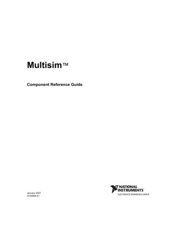
Principles of Electrical Engineering Lab 14. Move the cursor to the bottom-right of the workspace and left-click to place the component. Similarly, findthe other components and place them. When a part is on the workspace and you want to place the samepart again, highlight it and select Edit»Copy, then Edit» Paste. You can also select it from the In UseList and click to place it on the workspace. Press Ctrl R if you want to rotate the component.Theoscilloscope is obtained (by dragging it) from the component window on the right hand side of mainwindow.MultisimPage 3
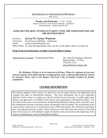
Principles of Electrical Engineering Lab 15. All components have pins that you use to wire them to other components or instruments. As soon asyour cursor is over a pin, Multisim knows you want to wire and the pointer changes to a crosshair.You can also use ctrl q for wiring the circuit. Don’t forget to add Ground to the circuit (available inSources option in Place Component).6. Choose the type of analysis you want to perform by clicking Simulate Analyses . Here, we havechosen transient analysis.MultisimPage 4
Principles of Electrical Engineering Lab 17. Select Simulate» Analyses»Transient Analysis and click on the Output tab. Add I(v1) to the rightcolumn by first clicking on I(v1) in left column and then pressing Add tab.8. Also choose the time (from transient Frequency parameters).9. Click on Simulate tab. The output window appears which consists of tab for oscillator ouput as well astransient waveforms. Different colored waves can be viewed by choosing the color of respective wireof the electrical quantity (voltage and current). Right click on wire in the circuit and then click on Colorsegment to choose the color of wire and thus the waveform color (after simulation).MultisimPage 5
Principles of Electrical Engineering Lab 1MultisimPage 6
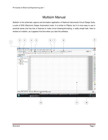
Principles of Electrical Engineering Lab 110. With multisim, you can create 3D breadboard with components placed. You can explore yourself thisoption by clicking on show breadboard tab on main toolbar. Figure below shows example of 3Dbreadboard created in multisim.MultisimPage 7
Principles of Electrical Engineering Lab 1 Multisim Page 2 1. The Menu Bar is where you find commands for all functions. 2. The Design Toolbox lets you navigate through the different types of