Transcription
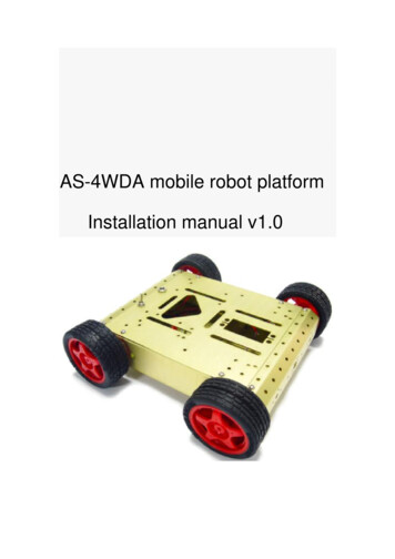
AS-4WDA mobile robot platformInstallation manual v1.0
一、 the parts list( 一 ) the list of components ( including scalable resource )IconName ( number )CodeName ( number )CodeThe platform plate(1)PT0Platform plate(1)Platform side(2)PT2Platform end plate(2)PT3Toggle switch(1)KG0Charging interface(1)CD0DC motor(4)DJ0Power supply box(1)DY0Wheel(4)CL0Icon
( 二) connecting parts listIconSNNameCodeSpecification and description1Cruciform slot screwSPM3 624 个 M3 62Cruciform slot screwSPM3 258 个 M3 253Six cornerLM316 个 M34Elastic washerDQ15Check washerDQ21 for the M6 thread parts6Elastic washerDQ31 for the M8 thread parts7Six cornerLM61 for the M6 thread parts8Six cornerLM81 for the M8 thread parts9Heat shrink tubeThe joint insulation10WirewayConnected component1 for the M6 thread parts
(三) a controller and power supply equipment (number controller may chooseone)arduino Controllerarduino mega ControllerDual H bridge DC motor driver boardOn board to consider a variety of controller is compatible, so has avariety of control hole, the convenience of customers makeUse.
二、 The use of tools1、cross screwdriver ( need to use 2 mm and 4 mm two specifications)2 、needle nose pliers三、The assembly stepsMatters needing attention:1 、carefully interpret the images and pay attention to installation order,in case of doubt can refer to the next installation diagram.2、 please note that manual red font part, avoid the error caused byrepeated disassembly and installation.3、 please be careful to use tools and cell polarity.4、is needed to keep the battery dry, do not use a long time should take outthe battery.5、do not let children touch the products of aluminum alloy parts,assembly should be far away from children, avoid the installation processAccidentally caused harm to children.
l Step 1: DC motor mountingTwo sides of the same motor installation, Pay attention to installationbefore the motor wiring electric soldering iron, a heat-shrinkabletube heating plasticSide plate can also be arranged models of standard DC gear motor
lStep 2Side and the lower plate installationl Step 2.1 drive plate installationDrive board mounting direction freely, pay attentionto the ipsilateral motor wiring direction sequence
l Step 2.2 are arranged in the battery boxThe battery box can be double-sided glue fixed, rear wheel motor wiring need toinsert the DuPont line cap, access interface of the stepping motorl Step 3 end plate installation
This section after the installation is complete, thereference below, if there is any difference in modifiedlStep3.1 infrared sensors and the headlight mounting( Extended )
If mounted headlights, in step 3 before completion, installation sharp infrareddistance sensor before, must first passSensor cable is inserted into the front baffle port, the other end is inserted intothe sensor interface, in order to prevent the sensor circuit board and the frontBaffle too close to cause a short circuit, can be mounted white nylon stringtransition, after the completion of the installation reference below.l Step 3.2 infrared obstacle avoidance sensorinstallation ( Extended )In the step 3 before installation, pay attention to the direction and spacing,spacing can be set to adjust,If the infrared obstacle avoidance sensor line, need toinstall the front baffle side.
l Step 4 with a charging interface switch installation(1)Charging switch kit production
(2)After the installation is complete, should be as below
(4)power switch and a charging connection diagraml Step 4.1 controller installationThis platform is provided with a variety of controller mounting hole, installArduino Mega168/328 controller, Arduino Mega1280/2560, Arduino UNO,
Seeeduino controller controller controller controller series,, 32 servo controller,the installation of Arduino Mega1280 controller effect diagram:l Step 4.2 two degrees of freedom servo platforminstallation ( Extended )
It not only can be installed models of two degree of freedom servo platform,also can be provided with a plurality of degrees of freedom mechanical arm,extended the application of stronger, the installation of two degree of freedomRB-421 steering head after effect chart:l Step 4.3 ultrasonic and infrared distance sensor mountingbracket ( Extended)
l Step 4.4 rotary ultrasonic detection installation( Extended )Note: before installing the servo steering gear, through the servocontroller, Arduino controller to the median ( 0 degree position)Step 5on board mounting
l Step 6 wheel mountingl Step 7 basic configuration mobile platform installationcompletion effect
Specifications and parameters:1、 driving motor gearbox ratio: 1:482 、driving motor no-load speed: 220rpm3 、wheel diameter: 65mm4 、wheel width: 26mm5 、platform length: 206mm6 、platform width: 200mm7 、platform height: 65mm8 、Platform weight: 620g9 、chassis ground distance: 13mm
The platform plate (1) PT0 Platform plate (1) Platform side (2) PT2 Platform end plate (2) . must first pass Sensor cable is inserted into the front baffle port, the other end is inserted into . l Step 7 basic configuration mobile platform installation completion effect . Specifications and parameters: 1、 driving motor .