Transcription
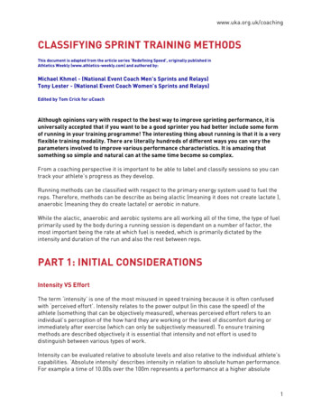
INTERNATIONAL JOURNAL OF SCIENTIFIC & TECHNOLOGY RESEARCH VOLUME 4, ISSUE 06, JUNE 2015ISSN 2277-8616Implementation Of Solid State Relays For PowerSystem ProtectionNidhi Verma, Kartik Gupta, Sheila MahapatraABSTRACT: This paper provides the implementation of solid state relays for enhancement of power system protection. Relays are an essential part ofthe power systems and are responsible for the control of any overload voltage or current and protection of the devices from these parameters. The mainfunction of the relay is to constantly monitor the parameter to be controlled and if it exceeds the percentage range set by the controller then it sends asignal to the circuit breaker to break the connection and isolate the faulty part. Solid state relays are preferred over mechanical relays and in this paperrelay functioning is done with the help of opto-coupler. Controlling of opto- coupler is done with the help of microcontroller. Circuit operates through ZeroVoltage Switching leading to reduction in harmonics. The implementation of relay circuit offers minimal delay time which enables better time response forprotection.KEYWORDS: Load, Microcontroller, opto-isolator, Relay, Software, Solid State Relays, Zero voltage switching—————————— ——————————INTRODUCTIONThere are many applications of protection circuit as theneed for energy to all has increased. With increasingpopulation, the energy demand has increased and so theneed to meet the need has increased. The major problem intransmission and distribution in country like India is lossesand the faults that occur during the process. Faultssometimes can be very dangerous to the machines beingused during generation, distribution and utilisation ofelectricity. Many protective devices are being usednowadays to avoid the consequences of faults.Throughout the industry a wide variety of application requirethe use of relays. Electrical power systems can beprotected against trouble and power blackouts usingsophisticated relays. These can also be utilised in thecontrol and regulation of power generation and distribution.Relays are used in a lot of home appliances as well, suchas dish washers, washing machines and refrigerators alongwith air condition or heating controls. Relays are commonlyassociated with electrical circuitry but there can bepneumatic and hydraulic relays as well.RELAYRelay is one such type of protective device. And circuitbreaker is utilised to remove the faulty part from the healthycircuit. A relay is a switch that works on the principle ofelectromagnetic induction. The switching between the ONand OFF position is done with the help of an electromagnetthus removing the need of a person’s presence. A relay canbe operated with a small amount of power and can be usedto control devices that draw much more power like circuitbreakers and isolators. For example the air conditioner inyour home is controlled with the help of relays. An AC unitrequires roughly 220VAC at around 30A, that comes out tobe around 6600 Watts however the coil used to control therelay may only need a few watts to pull the contactstogether. A relay is like a remote control switch and hasmany applications because of its long life, high accuracy,relative simplicity and proven high reliability. These are veryuseful when we have a requirement to control huge amountof voltage or current with use of a small electrical signal.Initially the contact is normally open which means notconnected. The coil generates a magnetic field whencurrent (I) is passed through it and closes the switch (i.e.top contact gets connected). A spring is used to again pullback the switch open, when power is removed from the coil.HOW DO RELAYS WORK Nidhi Verma is currently pursuing bachelors degreeprogram in electrical and electronics engineering inITM University, Gurgaon, India.E-mail: nidhi24680@gmail.com Kartik Gupta is currently pursuing bachelors degreeprogram in electrical and electronics engineering inITM University, Gurgaon, India.E-mail: kartikgupta11988@gmail.com Sheila Mahapatra is Assistant Professor (Sr.Scale) inITM University, Gurgaon, India.E-mail: sheila@itmindia.edu65IJSTR 2015www.ijstr.org
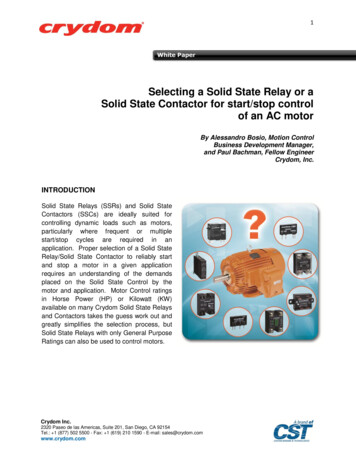
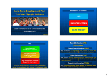
INTERNATIONAL JOURNAL OF SCIENTIFIC & TECHNOLOGY RESEARCH VOLUME 4, ISSUE 06, JUNE 2015The main part of the relay is the sensing unit whichbasically is an electrical coil. AC or DC current can be usedto power the coil. When applied current/ voltage increasesfrom the threshold value, the armature of the relay getsactivated by the coil, which is used to close the opencontacts. The switch mechanism is actuated by a magneticforce that is generated when power is supplied to the coil.When coil is energised it sends information to the circuitbreaker that breaks the circuit till the fault clearance orisolates the faulty part. The relay compares the current orvoltage from the transformer connected before the relayand send information to the circuit breaker. The coil openswhen the circuit breaker disconnects the faulty part.The basic functions performed by the relay are:On/Off Control- For example, in air conditioning control,relay is used to limit and control the compressor powerwhich is a ―high power‖ load. Limit Control - In this, relay isused to control a set of parameters and disconnect thedevice if the value of these parameters goes above orbelow the set value. For Example in Motor Speed Control,motor gets disconnected if the desired speed increases ordecreases beyond the limit. Logic Operation – In this, therelay is connected to desired point only if a particular logicis getting fulfilled. For example, in Test Equipment control,the instrument under test is connected to a number oftesting points.TYPES OF RELAYSRelay can be broadly classified on the basis of constructionand application. There are three types of relay based onconstruction which are Electromechanical, Static andNumerical.ISSN 2277-8616of heat sink, lower cost, availability of multiple poles andeasy switching in both AC and DC.B.) Static Relay (Solid State Relays)In this type of relay, the comparison or measurement ofelectrical quantities is performed by a static circuit whichgives an output signal for the tripping of a circuit breaker.These are known as static as they don’t have any movingpart. In this type of relay instead of magnetic coil ormechanical components we use analog electronic devicesto create the relay characteristics and the incoming currentor voltage waveforms are monitored by analog circuits, notdigitized. In these, there is no effect of gravity or vibration orshock. Sometimes, these relays use microprocessor butthey can’t be called microprocessor relays as it lacks theattribute of digital/numeric relay. These relays usesemiconductor devices like diodes, SCR, TRIAC, Powertransistor etc. to conduct load current. Relatively low controlcircuit energy is required to perform switching of the outputstate from OFF to ON position since there is use ofsemiconductor devices. To protect the circuit under controlfor introduction of electrical noises we often use staticrelays. Static relays are highly reliable and have a long life.They do not have any moving parts or contact bounce andthus have a fast response. Only single pole switching canbe accomplished using this relay. This acts as a majordrawback. Secondly they are costly as compared toelectromechanical relays.Type of SSR:It is convenient to classify the SSR by the nature of theinput circuit and the classification is as follows:1)Reed- Relay coupled SSRA.) Electromechanical RelaysThe above diagram shows the schematicelectromechanical relay. The parts are as follows: Spring Electromagnet Moveable armature Stationary contact Moveable contactofanIn this type of SSR application of control signal is done onthe coil of the reed relay. Thyristor switch is triggered whenthe appropriate circuitry is activated upon closing of reedswitch.The two contacts are kept separated with the help of aspring. When the electromagnet gets energized the twocontacts are pulled together. With proper application, theintegration between power circuits and control circuits canbe done with the help of electromechanical relays.Advantages of Electromechanical relays are no requirement66IJSTR 2015www.ijstr.org
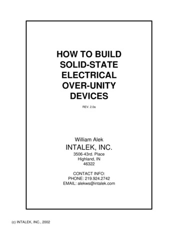
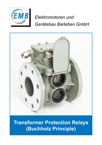
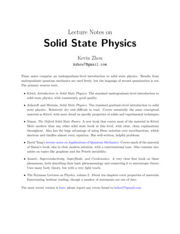
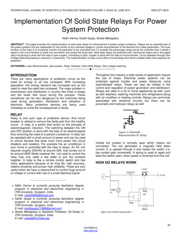
INTERNATIONAL JOURNAL OF SCIENTIFIC & TECHNOLOGY RESEARCH VOLUME 4, ISSUE 06, JUNE 20152)Transformer coupled SSRIn this type of relay a light or infrared source (generallyLED) is provided with a control signal. A photo- sensitivesemi- conductor device (diode, transistor or thyristor)detects the radiation from that source and generates anoutput. The output triggers the TRIAC which is used toswitch the load current. The electrical isolation is excellentas the input and output path are coupled only by a beam oflight. This type of SSR is discussed in detail below.In this type, primary of low-power transformer is providedwith the control signal, the thyristor switch is triggered bythe secondary that is generated by the primary excitation.Photo- Coupled SSRISSN 2277-8616C.) Numerical RelaysNumerical relays or digital relays are designed to carry outprotection function of various electrical equipments such asgenerator, transformer, transmission lines, motor etc. withthe use of digital technology. They use microcontroller witha software based protection algorithm for the electrical faultdetection. These are based on digital technology and aremore or less immune to variation or drift in parameters ofindividual components like OP-AMPS etc. due to changesin temperature, ageing etc. The reliability of the circuitincreases with the use of digital signals. These may includeprotection functions, metering and self- test functions.These are programmable types of relays. In this type ofrelay the behaviour along with the characteristics can beprogrammed. It can be used to accomplish variousprotection functions with appropriate modifications in thesoftware. This can be done either with the same hardwareor small adjustment may be required to be done in thedevice.SOLID STATE RELAYSThe block diagram of a solid state relay with opto-isolatormade by us is given below:67IJSTR 2015www.ijstr.org
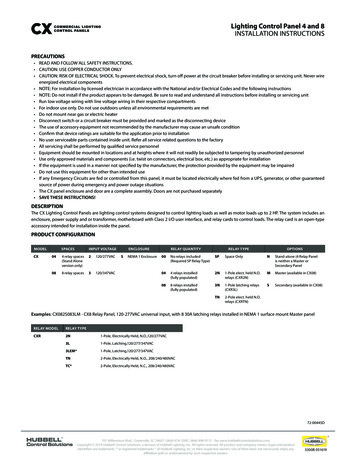
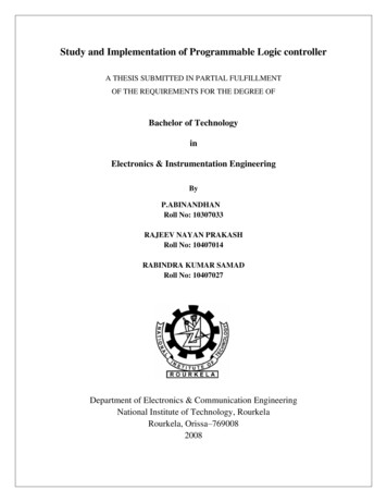
INTERNATIONAL JOURNAL OF SCIENTIFIC & TECHNOLOGY RESEARCH VOLUME 4, ISSUE 06, JUNE 2015ISSN 2277-8616The software implementation of the actual circuit is as follows:In the above circuit a power block is made with the help oftransformer, bridge rectifier and voltage regulator. Thisblock is to provide a voltage at 5V. This voltage is given tothe microcontroller for its further operation. Themicrocontroller is loaded with the code required for thecircuit operation. The input to the microcontroller is given bystart and stop push buttons which helps in generatingrandom output pulses to pin 21 of the microcontroller. The68IJSTR 2015www.ijstr.org
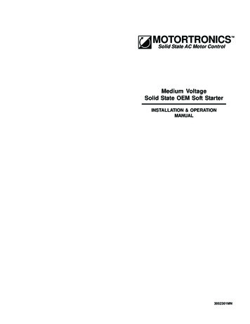
INTERNATIONAL JOURNAL OF SCIENTIFIC & TECHNOLOGY RESEARCH VOLUME 4, ISSUE 06, JUNE 2015random pulses are amplified with the help of transistors.The output of the transistor drives 3 opto-isolators. Theoutput of the opto-isolators drives respective TRIAC whichare connected in series with load in each phase. Optoisolator conducts only at zero- voltage crossing this implieseven if switching is done at the peak of the supply then alsoload will get ON only after zero crossing voltage of supplyvoltage. In zero voltage switching (ZVS) the turn-on andturn-off occurs at zero current and voltage, resulting in anessentially lossless switch. This is very easy in ac circuitsas the supply voltage itself gets zero 50-60 times a second.ZVS improves the life of controller as well as the load as itreduces the chances of arc formation in the relay. WithoutZVS the power could get turned on when the voltage is,may be 120VAC which could result to an electrical arc(spark). Signal going to the opto- isolator is controlled withthe help of pulse- width modulation technique. The output isobserved by the ON and OFF of the three lamps whichdepicts the three phase supply in the normal power system.Figure 8: Lamps are offISSN 2277-8616RESULTThe load gets turn on or off only at zero voltage, the supplybeing A.C. gets zero 50 times in one second if the supplyfrequency is 50Hz. The above output is shown on the CROacross the load. Resistive path was needed to be providedbetween the CRO and the load so as to bring the voltage inrange of CRO display. This could also be done by providingan isolated transformer across the load. By increasing thedelay we can get different output with which the flickering ofthe lamp (load) changes and similarly the output on theCRO changes.APPLICATION OF SOLID STATE RELAYS -Figure 9: Lamps are ON after pushing the push buttonSSR has gained favour in various regions that was earlierthe domain of electromechanical relay or contactor. Theseare increasingly used in transformers, lamps, temperaturecontrol, solenoids, motors and valves etc. Few applicationsinclude the following: Industrial automation, lighting and appliances Packaging and tooling machines Electronic appliances Manufacturing equipment Test and security systems Instrumentation system Production equipment On-board power control Traffic control Elevator control69IJSTR 2015www.ijstr.org
INTERNATIONAL JOURNAL OF SCIENTIFIC & TECHNOLOGY RESEARCH VOLUME 4, ISSUE 06, JUNE 2015 ISSN ngineering, Vol. 2, Issue 8, August 2013Vending machinesOffice machinesDisplay and entertainment lighting[3] Why use solid state relays? - www.crydom.comADVANTAGES OF SOLID STATE RELAYSSSR has neither moving parts to wear out nor arcingcontacts that are often the main cause of failure of EMR High degree of reliability Long life 109 operations Zero-voltage turn-on, low electro- magneticinduction Shock and vibration resistant No contact bounce which leads to arclessswitching Microprocessor compatible Fast response[4] Claude E. Shannon, ―A symbolic analysis of relayand switching circuits‖, book, IEEE press[5] Kevin R. [6] Relay Systems, by I. T. Monseth and P. H.Robinson, McGraw-Hill Book Co., New York, 1935.[7] Relays, National Plastic Heater Sensor and ControlCo., www.nphheaters.com[8] Solid state relays- www.omega.comAPPLICATION OF RELAYSFew applications of relay are as follows: General Purpose Relays can be used in OfficeEquipment, Pool and Spa, HVAC appliances andSecurity. Power Relays are used in Appliance Controls,Office and Vehicle Automation, Controlling ofvariousprocessesinindustries,EnergyManagement Systems, Motor Controls and HVAC. Low Signal Relays find their applications inDatacom, Telecommunications, CP/OA andSecurity devices. Solid State Relays are used for Motor Controls,Industrial Control and Timers. Signal Relays are used in Test Equipment,Instrumentation and Tele communications.CONCLUSIONThe paper provides implementation of solid state relayswith zero voltage switching. Relay plays a pivotal role inmodern power system protection to sense and isolatedifferent types of fault in the power circuit. The selection ofrelays depends on power rating, voltage and current rating,effect of external factors etc. The software and hardwareimplementation of the solid state relay designed usingmicrocontroller and opto-coupler is provided in the paper.Due to the use of semiconductor, arcless switching ispossible with which the efficiency, reliability and life time ofthe protection unit increases. The output across the load ona CRO clearly depicts that the power losses duringswitching are reduced to a minimal value due to zerovoltage switching. Isolation of faulty sections of powercircuit during zero voltage switching leads to reduction inharmonics.REFERENCES[1] Three phase solid state relays – POWERSEMwww.powersem.net[2] Anil Kumar Reddy. K, Sirisha. S.,‖A ZVS DC-DCCONVERTER WITH SPECIFIC VOLTAGE GAINFOR INVERTER OPERATIONUSED FOR 3PHASE INDUCTION MOTOR OPERATION‖International Journal of Advanced Research in70IJSTR 2015www.ijstr.org
System Protection Nidhi Verma, Kartik Gupta, Sheila Mahapatra ABSTRACT: This paper provides the implementation of solid state relays for enhancement of power system protection. Relays are an essential part of the power systems and are responsible for the control of any overload voltage or current and protection of the devices from these parameters.