Transcription
FACULTEIT IngenieurswetenschappenVAKGROEP WerktuigkundeAutonomous Mobile RobotMechanical DesignEindwerk ingediend tot het behalen van de academische graadburgerlijk werktuigkundig-elektrotechnisch ingenieurKristof GorisAcademiejaar 2004-2005Promotor: Prof. Dr. Ir. Dirk LefeberCo-Promotor: Prof. Dr. Ir. Hichem Sahli
Autonomous Mobile Robot: Mechanical DesignAcknowledgementsMany people have helped me along the way. Their guidance, good humour, adviceand inspiration sustained me trough the months of work. First of all, I’d like to thankall of them.Furthermore, I thank Mark and Guillermo for a nice cooperation during this project.I wish to thank my promotors Prof. Dr. Ir. Dirk Lefeber and Prof. Dr. Ir. HichemSahli for proposing this challenging project. And for their confidence in my abilities.Many thanks go out to my supervisors, the support of Ir. Ronald Van Ham, Ir. BramVanderborght, Ir. Thomas Geerinck, and Ir. Geert De Cubber kept me on the righttrack during the year.Many thanks go out to Jean-Paul Schepens, André Plasschaert, Gabriël Van denNest, Daniel Debondt, Eduard Schots and Thierry Lenoir for their technical support,great work, and patience with me.Furthermore, I wish to thank the WERK department for placing its infrastructure andmaterial at my disposal.Finally I’d like to thank family and friends for being so supportive. I wouldn’t havemanaged without them.II
Autonomous Mobile Robot: Mechanical DesignExecutive SummariesAutonomous Mobile Robot: Mechanical DesignThe design of autonomous mobile robots capable of intelligent motion and actionwithout requiring either a guide to follow or a teleoperator control involves theintegration of many different bodies of knowledge. This makes mobile robotics achallenge worthwhile. To solve locomotion problems the mobile roboticist mustunderstand mechanisms and kinematics, dynamics and control theory. To createrobust perceptual systems, the mobile roboticist must leverage the fields of signalanalysis and specialized bodies of knowledge such as computer visions to properlyemploy a multitude of sensor technologies. Localization and navigation demandknowledge of computer algorithms, information theory, artificial intelligence, andprobability theory.This thesis aims at building a locomotion mechanism that forms the base of acomplete mobile robot system capable of finding its way autonomously through apath filled with obstacles. To accomplish this task, locomotion mechanisms and theirkinematics have to be studied, mechanisms have to be designed and developed. Theimplementation of high and low level operating systems and electronics is requiredas well to control the chassis’ motion.III
Autonomous Mobile Robot: Mechanical DesignAutonome Mobiele Robot: Mechanisch OntwerpHet ontwerp van een autonome mobiele robot die in staat moet zijn intelligentebewegingen en acties uit te voeren zonder hulp van een operator of gids, vereist tmobieleroboticainterdisciplinair en vervolgens een boeiende uitdaging. Om problemen op te lossenomtrent beweging moet men kennis nemen van mechanica, kinematica, dynamica encontrole theorie. Robuuste gewaarwording systemen vereisen de kennis van signaalanalyse en computer beeldverwerking, evenals sensor technologieën. Plaatsbepalingen navigatie vereisen computer algoritmes, informatie theorie, artificiële intelligentieen waarschijnlijkheid theorie.Het doel van deze thesis bestaat erin een bewegings mechanisme uit te werken dat debasis vormt voor een complete mobiele robot die in staat is om zelfstandig zijn wegte vinden doorheen een met obstakels gevulde ruimte. Hiertoe worden verscheidenemogelijke bewegings mechanismen en hun kinematica bestudeerd, en mechanismenworden ontworpen en ontwikkeld. Om de beweging van het chassis te verschillendeniveausgeïmplementeerd.IV
Autonomous Mobile Robot: Mechanical DesignLe robot mobile autonome : le projet mécaniqueL’ébauche d’un robot mobile autonome qui doit être capable de se mouvoirintelligemment et d’exécuter des actions sans l’aide d’un opérateur ou d’un guide,exige l’intégration de différentes technologies. Cela implique que la robotiquemobile devient interdisciplinaire et de ce fait un défi captivant. Pour résoudre desproblèmes de mouvement, la robotique mobile a besoin de la connaissance de lamécanique, de la cinématique, de la dynamique et de la théorie de contrôle. Dessystèmes robustes de perception exigent la connaissance de l’analyse des signaux etdu traitement des images par ordinateur ainsi que des technologies de détection. Lalocalisation et la navigation exigent la connaissance des algorithmes informatiques,la théorie d’information, l’intelligence artificielle et la théorie de probabilité.Le but de cette thèse consiste à développer un mécanisme de mouvement qui est labase d’un robot mobile complet capable de trouver son chemin d’une façonautonome à travers un espace parsemé d’obstacles. Pour accomplir cette tâche, lesdifférents mécanismes de mouvements possibles et leur cinématique ont été étudiéset des mécanismes ont été conçus et développés. Pour contrôler les mouvements duchâssis, des systèmes de commande et des systèmes électroniques sur différentsniveaux ont été mis en œuvre.V
Autonomous Mobile Robot: Mechanical DesignContentsAcknowledgementsIIExecutive SummariesIII1 Introduction11.1 Objectives1.2 Overview of the Thesis1223Basic Concepts of Design2.1 Introduction2.2 Problem Statement2.3 Definitions of Terms2.3.1 Robot2.3.2 Mobility2.3.3 Autonomous2.3.4 Holonomic and Non Holonomic34556773 Wheeled Mobile Robots93.1 Introduction3.2 The Wheel and Rolling3.2.1 Principle of Rolling3.2.2 Wheel Classification3.3 Wheel Configuration3.3.1 Overview3.3.2 Summary91111111414274 Design and Development284.1 Concept4.1.1 General Dimensions and Robot Shape4.1.2 Wheel Configuration and Wheels4.1.3 Modularity4.2 Energy Supply4.2.1 Battery Pack4.2.2 Case Study4.2.3 Autonomy4.2.4 Battery Charger4.3 Mechanic design4.3.1 Robot’s Leg4.3.1.1 Driven Steered Standard Wheel4.3.1.2 Bearings4.3.2 Motors4.3.2.1 Drive Motor4.3.2.2 Steer Motor4.3.3 Frame and Transmission2829303234343637383940404546464953VI
Autonomous Mobile Robot: Mechanical Design4.3.3.1 Frame4.3.3.2 Transmission4.4 Electronic design4.4.1 Drive Motor Electronics4.4.1.1 Inputs4.4.1.2 Outputs4.4.2 Steer Motor Electronics4.4.2.1 Inputs4.4.2.2 Outputs4.4.3 Interface Electronics4.4.3.1 Microcontroller4.4.3.2 Voltage Regulation4.4.3.3 Communication and Programming4.4.3.4 Digital to Analogue Converter4.4.3.5 Analogue to Digital Converter4.5 Software design535558606161626363646565666666675 Kinematics725.1 Introduction5.2 Kinematics5.2.1 Representing Robot’s Position5.2.2 Kinematic Wheel Model5.2.3 Kinematic Robot Model5.2.3.1 Degree of Mobility5.2.3.2 Degree of Steerability5.2.3.3 Degree of Manoeuvrability5.2.4 Synchro Drive7273737576788081816 Conclusions and Further Work836.1 Conclusions6.2 Further Work8384Abbreviations85List of figures86References88Appendix AAppendix BVII
Introduction1 Introduction1.1ObjectivesThe design of autonomous mobile robots capable of intelligent motion and actioninvolves the integration of many different bodies of knowledge. The aim of thisproject is to idealise an existing autonomous mobile robot, on all levels. Thisincludes the mechanics, kinematics, dynamics, perception, sensor fusion,localization, path planning and navigation. All these aspects have to be reviewed andmodified to a modular system, if necessary new modular modules have to bedesigned and developed. This way a robust and modular autonomous mobile robot,capable of intelligent motion and performing different tasks will arise. One of itstasks could be winning the ‘Melexis Safety Throphy 2006’.To obtain this aim, the workload is divided between three students. The thesis part ofMark Nelissen is to write anew the software for the robot, making it also modularand as independent of the hardware as possible. This consists of implementing lastyear’s robot software, developed by Jan, Thomas and Bart [4], onto a new andmodular framework.The thesis part of Guillermo Moreno is fully devoted to the development of amodular sensor set up. This is designing the low level electronics and software incharge of both controlling the different sensors hardware and saving the dataproperly. Also a bus system, aimed at communicating with the on board PC,supporting different sensor modules, is worked out.This thesis will handle the problems concerning locomotion mechanisms, kinematics,dynamics, and control and operating systems.1
Introduction1.2Overview of the ThesisIn ‘chapter 2: Basic Design Concepts,’ some frequently used terms are explained andthe general approach to a mechanical design is given.In order to take notice of the problems in the existing robot, and to be able toidealise, or redesign a locomotion mechanism, a study is needed on the existing stateof-the art locomotion mechanisms. This general study is presented in ‘Chapter 3:Wheeled Mobile Robots.’ Different wheels and wheel configurations are discussed indetail in this chapter.The next chapter, ‘Chapter 4: Design and Development,’ is dedicated to the designand development of a new locomotion mechanism, and the implementation of itsdesigned and developed electronics and operating software. This is the core chapterof the thesis.‘Chapter 5: Kinematics,’ deals with the in chapter 4 designed chassis’ kinematics.Finally, conclusions are made and proposals for future work are enlightened in‘Chapter 6: Conclusions and Further Work.’2
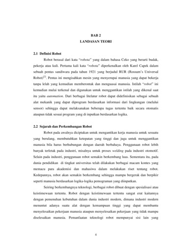
Basic Design Concepts2 Basic Design Concepts2.1IntroductionMechanical engineering design is mainly a creative activity which involves a rationaldecision making process. Generally speaking, it is directed at the satisfaction of aparticular need by means of a mechanical system, whose general configuration,performance specifications and detailed definition conform the ultimate task of thedesign activity.[7] There is no unified approach or methodology to actually design asystem, in so much as there does not exist a unified approach to creativity. Given aparticular need, each individual designer would probably design something different.There are however, some common guidelines which can be useful in a very generalway. These guidelines are variations of the so called ‘design process’ (Fig.2.1),which is a stepwise description of the main tasks typically developed in acomprehensive design exercise. In any case, one of the main tasks in any designsituation is the so called ‘definition of the problem’ or ‘problem statement’.[7]3
Basic Design ConceptsCONFONT NEEDREQUIREMENTSPROPOSE CONCEPTREDESIGNDESIGN SYSTEMANALYZE SYSTEMREFINE DESIGNFABRICATE PROTOTYPETEST PROTOTYPEPRODUCTION PLANNINGPRODUCTIONENDFig.2.12.2A sequential Design Process [7]Problem StatementWhat are the requirements? This is the main question to solve before designing amechanism. Wanted here is a robot platform modular in every way, and thepossibility to join the ‘Melexis Safety Trophy’ is desirable. To achieve this goal therules of the contest need to be known. These rules are a serious limitation of thepossibilities. A short overview is stated underneath. The challenge of the MelexisSafety Trophy is to develop an autonomous robot that is able to drive safely frompoint A to point B. The environment is similar to a real traffic situation with lanes,road signs, traffic lights and other vehicles. More details about the concept and4
Basic Design Conceptsspecifications concerning the dimensions of tracks, lanes, road signs and obstaclescan be found in [5]. The robot’s most important specifications at this point are:Maximum and minimum dimensions; there is no maximal length, the width hasto be between 200mm and 450mm and the maximum height is 500mm.Drive; only electrical power is authorized, so no combustion engines may beused.Locomotion; all robots need to use wheels. These wheels need to be big enoughto cope with small irregularities of the floor.Cost; the robot may not cost more than 2500. Borrowed or sponsored partscount for their replacement value with exception of one personal computer orlaptop and one car battery, because these can be reused.In order to construct a conform wheeled autonomous robot, some design decisionshave to be made. Before decisions can be made some terms have to be explained.2.32.3.1Definitions of TermsRobotA robot can be defined as ‘a mechanical device which performs automated tasks,either according to direct human supervision, a pre-defined program or, a set ofgeneral guidelines, using artificial intelligence techniques.’[1],[8] The firstcommercial robot was developed in 1961 and used in the automotive industry byFord. The robots were principally intended to replace humans in monotonous, heavyand hazardous processes. Nowadays, stimulated by economic reasons, industrialrobots are intensively used in a very wide variety of applications. Most of theindustrial robots are stationary. They operate from a fixed position and have limitedoperating range. The surrounding area of the robot is usually designed in function of5
Basic Design Conceptsthe task of the robot and then secured from external influences. These robotsefficiently complete tasks such as welding, drilling, assembling, painting andpackaging.However, in many applications it can be useful to build a robot which can operatewith larger mobility. In contrast to most stationary robots, where the surroundingspace is adapted to suit the robot tasks, mobile robots have to adapt their behaviourto their surroundings. Instead of performing a fixed sequence of actions, mobilerobots need to develop some awareness of their environment through interaction withall kind of sensors; they use on-board intelligence to determine the best action totake. The development of intelligent navigation systems on mobile robots, whichensures efficient and collision free movement, is still the centre of several researchprojects. [1]2.3.2MobilityMobile robots are generally those robots which can move from place to place acrossthe ground. Mobility give a robot a much greater flexibility to perform new,complex, exciting tasks. The world does not have to be modified to bring all neededitems within reach of the robot. The robots can move where needed. Fewer robotscan be used. Robots with mobility can perform more natural tasks in which theenvironment is not designed specially for them. These robots can work in a humancentred space and cooperate with men by sharing a workspace together.[9]A mobile robot needs locomotion mechanisms that enable it to move unboundedthroughout its environment. There is a large variety of possible ways to move whichmakes the selection of a robot’s approach to locomotion an important aspect ofmobile robot design. Most of these locomotion mechanisms have been inspired bytheir biological counterparts which are adapted to different environments andpurposes.[9],[10] Many biologically inspired robots walk, crawl, slither, and hop.6
Basic Design Concepts2.3.3AutonomousAn autonomous robot is capable of detecting objects by means of sensors or camerasand of processing this information into movement without a remote control.2.3.4Holonomic and Non HolonomicIn mobile robotics the terms omnidirectional, holonomic and non holonomic areoften used, a discussion of their use will be helpful.[9]The terms holonomic and omnidirectional are sometimes used redundantly, often tothe confusion of both. Omnidirectional is a poorly defined term which simply meansthe ability to move in any direction. Because of the planar nature of mobile robots,the operational space they occupy contains only three dimensions which are mostcommonly thought of as the x, y global position of a point on the robot and theglobal orientation, θ, of the robot. Whether a robot is omnidirectional is not generallyagreed upon whether this is a two-dimensional direction, x, y or a three-dimensionaldirection, x, y, θ.In this context a non holonomic mobile robot has the following properties:The robot configuration is described by more than three coordinates. Threevalues are needed to describe the location and orientation of the robot, whileothers are needed to describe the internal geometry.The robot has two DOF, or three DOF with singularities. (One DOF iskinematically possible but is it a robot then?)In this context a holonomic mobile robot has the following properties:The robot configuration is described by three coordinates. The internal geometrydoes not appear in the kinematic equations of the abstract mobile robot, so it canbe ignored.7
Basic Design ConceptsThe robot has three DOF without singularities.The robot can instantly develop a wrench in an arbitrary combination ofdirections x, y, θ.The robot can instantly accelerate in an arbitrary combination of directions x, y,θ.Non holonomic robots are most prevalent because of their simple design and ease ofcontrol. By their nature, non holonomic mobile robots have fewer degrees offreedom than holonomic mobile robots. These few actuated degrees of freedom innon holonomic mobile robots are often either independently controllable ormechanically decoupled, further simplifying the low-level control of the robot. Sincethey have fewer degrees of freedom, there are certain motions they cannot perform.This creates difficult problems for motion planning and implementation of reactivebehaviours.Holonomic however, offer full mobility with the same number of degrees of freedomas the environment. This makes path planning easier because there aren’t constraintsthat need to be integrated. Implementing reactive behaviours is easy because thereare no constraints which limit the directions in which the robot can accelerate.8
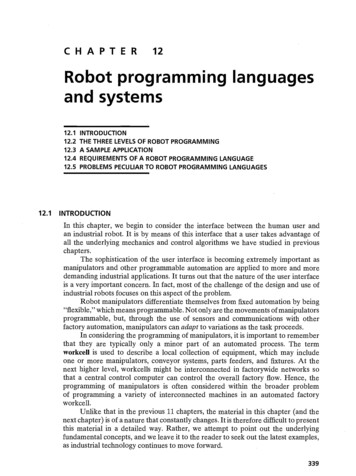
Wheeled Mobile Robots3 Wheeled Mobile Robots3.1IntroductionBefore we design and develop our own locomotion mechanism, we have to study theexisting mechanisms and compare their benefits an disadvantages.Although a lot of locomotion mechanisms have been inspired by their biologicalcounterparts, nature did not develop a fully rotating, actively powered joint, which isthe technology necessary for wheeled locomotion. This mechanism is not completelyforeign to biological systems. Our bipedal walking system can be approximated by arolling polygon, with sides equal in length d to the span of the step, shown inFig.3.1.[10] As the step size decreases, the polygon approaches a circle or wheel. Ingeneral, legged locomotion requires higher degrees of freedom and therefore greatermechanical complexity than wheeled locomotion.[9]Fig.3.1A biped walking system can approximated by arolling polygon, with sides equal in length d to thespan of the step. As the step size decreases, thepolygon approaches a circle or wheel with radius l.Fig.3.2Specific power versus attainable speed of variouslocomotion mechanisms9
Wheeled Mobile RobotsThe wheel has been by far the most popular locomotion mechanism in mobilerobotics and in man-made vehicles in general. It can achieve very good efficiencies,as demonstrated in Fig.3.2 [10], and does so with a relatively simple mechanicalimplementation. Wheels are extremely well suited for flat surfaces where this type oflocomotion is more efficient than a legged one. For example the railway is ideallyengineered for wheeled locomotion because rolling friction is minimized on a hardand flat steel surface. When the surface becomes soft, wheeled locomotionaccumulates inefficiencies due to rolling friction whereas legged locomotion suffersmuch less because it consists only of point contacts with the ground. This dramaticloss of efficiency in the case of a tire on soft ground is also shown in Fig.3.2. [10]Nature favours legged locomotion, because of its rough and unstructured terrain. Incontrast the human environment frequently consists of engineered, smooth surfaces,both indoors and outdoors. Therefore virtually all industrial applications of mobilerobotics utilize some form of wheeled locomotion. In this thesis we shall not delve inthe theory concerning legged robots. We will however explain the wheel theory inmore detail since there is a very large space of possible kinds of wheels and theirconfigurations when one considers possible techniques for mobile robot locomotion.10
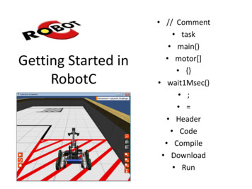
Wheeled Mobile Robots3.2The Wheel and Rolling3.2.1Principle of RollingA wheel (as used here) is rotationally symmetric about its principal or roll axis andrests on the ground on its contact patch. The contact patch is a small area which is infrictional contact with the ground such that the forces required to cause relativesliding between the wheel and ground are large for linear displacements and smallfor rotational motions. Thus, we assume that a wheel undergoing pure rolling has acontact point with no slip laterally or longitudinally, yet is free to twist about thecontact point. [9]The kinematic constraint of rolling is called a higher-pair joint. The kinematic pairhas two constraints so that two degrees of freedom are lost by virtue of the rollingconstraint.3.2.2Wheel ClassificationThere are three major wheel classes. They differ widely in their kinematics, andtherefore the choice of wheel type has a large effect on the overall kinematics of themobile robot. The choice of wheel types for a mobile robot is strongly linked to thechoice of wheel arrangement, or wheel geometry. The mobile robot designer mustconsider these two issues simultaneously when designing the locomotion mechanismof a wheeled robot.First of all there is the standard wheel as shown in Fig.3.3. This is what most peoplethink of when asked to picture a wheel. The standard wheel has a roll axis parallel tothe plane of the floor and can change orientation by rotating about an axis normal tothe ground through the contact point. The standard wheel has two DOF. A fixed11
Wheeled Mobile RobotsFig.3.3Standard Wheels, from left to right: Fixed, Steered, Lateral Offset, Castorstandard wheel is mounted directly to the robot body. When the wheel is mounted ona rotational link with the axis of rotation passing through the contact point, we speakof a steered standard wheel. A variation which reduce rotational slip during steeringis called the lateral offset wheel. The wheel axis still intersects the roll axis but not atthe contact point. The caster offset standard wheel, also know as the castor wheel,has a rotational link with a vertical steer axis skew to the roll axis. The key differencebetween the fixed wheel and the castor wheel is that the fixed wheel can accomplisha steering motion with no side effects, as the centre of rotation passes through thecontact patch with the ground, whereas the castor wheel rotates around an offset axis,causing a force to be imparted to the robot chassis during steering.[9],[10]The second type of wheel is the omnidirectional wheel. This is a disk with amultitude of conventional standard wheels mounted on its periphery as shown inFig.3.4.[9] The omnidirectional wheel has tree DOF and functions as a normalwheel, but provides low resistance in another direction as well. The angle of theperipheral wheels may be changed to yield different properties. The small rollersattached around the circumference of the wheel are passive and the wheel’s primaryaxis serves as the only actively powered joint. The key advantage of this design isthat, although the wheel rotation is powered only along the one principal axis, the12
Wheeled Mobile RobotsFig.3.4Omnidirectional Wheels, form left to right: Universal, Double Universal, Swedish 45 wheel can kinematically move with very little friction along many possibletrajectories, not just forward and backward.[10]The third type of wheel is the ball or spherical wheel. It has also three DOF. Thespherical wheel is a truly omnidirectional wheel, often designed so that it may beactively powered to spin along any direction. There have not been many attempts tobuild a mobile robot with ball wheels because of the difficulties in confining andpowering a sphere. One mechanism for implementing this spherical design imitatesthe computer mouse, providing actively powered rollers that rest against the topsurface of the sphere and impart rotational force.[9][10]13
Wheeled Mobile Robots3.33.3.1Wheel ConfigurationOverviewThe wheel type and wheel configuration are of tremendous importance, they form aninseparable relation and they influence three fundamental characteristics of a:manoeuvrability, controllability, and stability. In general there is an inversecorrelation between controllability and manoeuvrability.The most popular wheel configurations are illustrated with an example below. Theused symbols are explained in Fig.3.5. The number of wheels rise from two to fouror more. A brief influence on stability, controllability and manoeuvrability is giventoo.Standard Fixed WheelStandard Driven WheelStandard Non Driven Steer WheelStandard Driven Steer WheelOmnidirectional WheelCastor WheelLinear ActuatorFig.3.5Legende14
Wheeled Mobile RobotsWheel configurations with two wheels are shown in Fig.3.6 and Fig.3.7 and inFig.3.8 and Fig.3.9. The first two-wheeled configuration is similar to the mechanismof bikes, and motorcycles. At the front there is a steer wheel which enables thechange in orientation, and at the rear a powered drive wheel is mounted. Thisconfiguration leads to a static instability when the mechanism is not driven.Fig.3.6Static unstable two-wheeled configurationFig.3.7BikeSurprisingly, the minimum number of wheels required for static stability is two. Asshown in Fig.3.8, a two-wheel differential drive robot can achieve static stability ifthe centre of mass is below the wheel axle. However, under ordinary circumstancessuch a solution requires wheel diameters that are impractically large. A commercialmobile robot that uses this wheel configuration is shown in Fig.3.9.15
Wheeled Mobile RobotsFig.3.8Static stable two-wheeled configuration, if the centreof mass is below the wheel axleFig.3.9Cye, a commercial two-wheel differential-drive robotConventionally, static stability requires a minimum of three wheels, with theadditional condition that the centre of gravity must be contained within the triangleformed by the ground contact points of the wheels.The differential drive is a two-wheeled drive system with independent actuators foreach wheel. The name refers to the fact that the motion vector of the robot is sum ofthe independent wheel motions, something that is also true of the mechanicaldifferential. The drive wheels are usually placed on each side of the robot. A nondriven wheel, often a castor wheel, forms a tripod-like support structure for the bodyof the robot. Unfortunately, castors can cause problems if the robot reverses itsdirection. Then the castor wheel must turn half a circle and, in the process, the offsetswivel can impart an undesired motion vector to the robot. This may result in to atranslation heading error. Straight line motion is accomplished by turning the drivewheels at the same rate in the same direction. That is not as easy as it sounds. In16
Wheeled Mobile Robotsplace rotation is done by turning the drive wheels at the same rate in the oppositedirection. Arbitrary motion paths can be implemented by dynamically modifying theangular velocity and/or direction of the drive wheels. The benefits of this wheelconfiguration is its simplicity. A differential drive system needs only two motors,one for each drive wheel. Often the wheel is directly connected to the motor withinternal gear reduction. The robot described in [1],[2],[3] and [4] has this wheelconfiguration. Despite is simplicity, the controllability is rather difficult. Especiallyto make a differential drive robot move in a straight line. Since the drive wheels areindependent, if they are not turning at exactly the same rate the robot will veer to oneside. Making the drive motors turn at the same rate is a challenge due to slightdifferences in the motors, friction differences in the drive trains, and frictiondifferences in the wheel-ground interface. To ensure that the robot is travelling in astraight line, it may be necessary to adjust the motor speed very often. This mayrequire interrupt-based software and assembly language programming. It is also veryFig.3.10Differential drive configuration with two drive wheels anda castor wheelFig.3.11Khepera, a small differential drive robot17
Wheeled Mobile Robotsimportant to have accurate information on wheel position. This usually comes fromthe encoders. A round shape differential drive configuration is shown in Fig.3.10.An other three-wheel configuration is the tri-cycle drive, shown in Fig.3.11 andFig.3.13. The difference between these two mechanisms are the way they steer anddrive. The first tri-cycle drive has a non driven steer wheel at the front/rear to changeorientation. The drive wheels are at the rear/front of the vehicle. A differential isnecessary when the wheels can not slip to avoid mechanical destruction. The secondtri-cycle drive has a combined steer and drive mechanism at the front/rear. Two freewheels are mounted on the structure at the rear/front to maintain stability. It is up tothe robot designer to decide. Both possibilities have there benefits and disadvantages.It is difficult to find a small differential, but it is also difficult to build a mechanismthat steers and drives at the same time. The tri-cycle drive has some seriousdisadvantages common to the car drive configuration, those are explain later.Fig.3.12Tri-cycle drive, front/rear steering and rear/front drivingFig.3.13Piaggio mini truck18
Wheeled Mobile RobotsFig.3.14Tri-cycle drive, combined steering and driving.Fig.3.15NeptuneAnother three wheel configuration is the synchro drive. The synchro drive system isa two motor drive configuration where one motor rotates all wheels together toproduce motion and
First of all, I'd like to thank all of them. . Autonomous Mobile Robot: Mechanical Design 4.3.3.1 Frame 53 4.3.3.2 Transmission 55 4.4 Electronic design 58 4.4.1 Drive Motor Electronics 60 . Wanted here is a robot platform modular in every way, and the