Transcription
per-Based, Capacitive Touch PadsAaron D. Mazzeo, William B. Kalb, Lawrence Chan, Matthew G. Killian,Jean-Francis Bloch, Brian A. Mazzeo, and George M. Whitesides*This paper describes low-cost, thin, and pliable touch padsconstructed from a commercially available, metallized papercommonly used as packaging material for beverages and bookcovers. The associated electronics with the individual keys inthe touch pads detect changes in capacitance or contact withfingers by using the effective capacitance of the human bodyand the electrical impedance across the tip of a finger. To createthe individual keys, a laser cutter ablates lines through the filmof evaporated aluminum on the metallized paper to pattern distinct, conductive regions. This work includes the experimentalcharacterization of two types of capacitive buttons and illustrates their use with applications in a keypad with 10 individually addressable keys, a keypad that conforms to a cube, and akeypad on an alarmed cardboard box. With their easily arrayedkeys, environmentally benign material, and low cost, the touchpads have the potential to contribute to future developments indisposable, flexible electronics, active, “smart” packaging, userinterfaces for biomedical instrumentation, biomedical devicesfor the developing world, applications for monitoring animaland plant health, food and water quality, and disposable games(e.g., providers of content for consumer products).There is no simple method of integrating buttons withstructures on single-use or throw-away devices. Current commercial buttons are not thin enough, inexpensive enough, oreasy enough to array seamlessly with paper-based products fordisposable applications. The touch pads in this work are thin( 60 μm in some cases), simple to array, fabricated by etchingpatterns into metallized paper, low-cost ( 0.25 m 2 for the thingrade of metallized paper we use in this work), and lightweightDr. A. D. Mazzeo, W. B. Kalb, L. Chan,M. G. Killian, Prof. G. M. WhitesidesDepartment of Chemistry and Chemical BiologyHarvard University12 Oxford St., Cambridge, MA 02138, USAE-mail: gwhitesides@gmwgroup.harvard.eduProf. J.-F. BlochDepartment of Papermaking Engineering - LGP2Grenoble Institute of Technology461 rue de la Papeterie, BP65 - 38402 Saint Martin d’HèresCedex, FranceProf. B. A. MazzeoDepartment of Electrical and Computer EngineeringBrigham Young University459 Clyde Building, Provo, UT 84602, USAProf. G. M. WhitesidesWyss Institute for Biologically Inspired Engineering at Harvard University3 Blackfan Circle, Boston, MA 02115, USADOI: 00s of g m 2). The individual keys measure changes in capacitance when touched by a user, and the buttons require nophysical displacement of conductive elements. Even though theindividual keys on the touch pads detect changes in capacitance,the paper-based keypads are still functional when touched byfingers in nitrile gloves.Developments in paper-based electronics include ring oscillators with organic electronics,[1] transistors,[2–4] methods forpatterning conductive traces,[5–7] speakers,[8] supercapacitors,[9]batteries,[10] MEMS,[11] and solar cells.[12] Each of these developments focuses on a single technological advance that wouldenable new types of consumer products. Many types of newconsumer products will require some form of user interfaceor input. In order to gather key strokes from end users withpolymer-based or textile-based flexible electronics, it is possibleto use changes in resistance[13] or capacitance.[14–17] Obviously,technology being developed commercially–Samsung, 3M, Displax, Elo TouchSystems, and other companies are pursuing technology for transparent touch-based systems–for use with glassbased displays on mobile phones or computer screens mightalso be applicable to future developments in one-time use, paperbased electronics. Conventional capacitive touch screens detectchanges in capacitance through a piece of glass with a thicknessmuch greater than that of the polymeric coatings on top of themetallized paper. Thus, instead of detecting changes in capacitance of 10s or 100s of pF, they use optimized electronics todetect changes closer to 1 pF. Besides a patent for capacitive buttons on posters,[18] there are no descriptions for simple methodsof receiving input/key strokes on paper-based substrates.Metallized paper is a commodity. It is easy to ablate orcut the metal film with a laser or razor blade, and paper isboth durable (i.e., documents can last for years) and disposable. Touch pads made from metallized paper may fill a nichebetween displays with touch screens and conventional commercial keypads. The metallized paper (A-238 and A-550 fromVacumet Corporation) consists of cellulose, polymeric coatings, and evaporated aluminum (see Supporting Information(SI) Figure 1). The cellulose serves primarily as structural support for a 10-nm thick, conductive layer of evaporated aluminum. The metallized layer without structural support wouldnot have sufficient strength for manual handling or use. Thepolymer-based portions of the paper assist in adhering themetallized layer to the cellulose and protect the thin, metallized layer from scraping or other environmental damage. Theuncoated side of the metallized paper has exposed cellulosebased paper, which can absorb moisture, while the polymericcoating on the opposite side of the paper blocks moisture.Nevertheless, using the laser cutter to ablate through the polymeric coating can make the metallized paper more susceptibleto moisture on the coated side. Experiments have also shown 2012 WILEY-VCH Verlag GmbH & Co. KGaA, WeinheimAdv. Mater. 2012, 24, 2850–2856
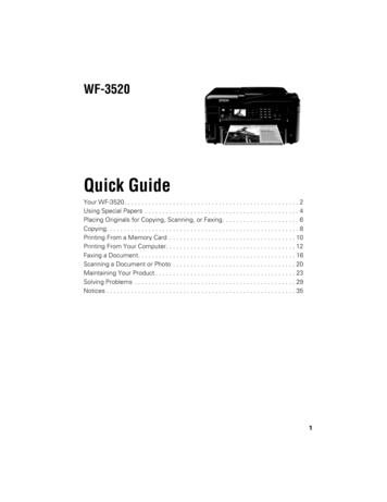
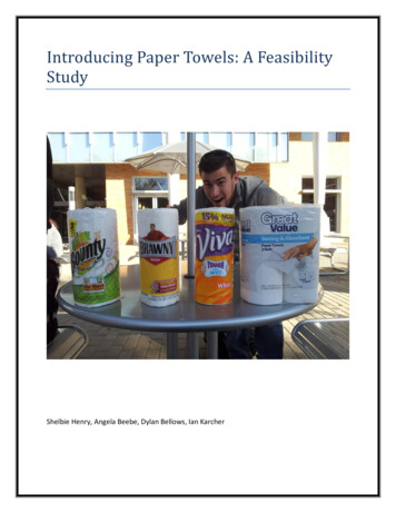
www.advmat.dewww.MaterialsViews.comAdv. Mater. 2012, 24, 2850–2856 2012 WILEY-VCH Verlag GmbH & Co. KGaA, ce (Zb) (see Figure 1A-D). This electrical impedance acts as a “body capacitor”with an approximate capacitance of 100 pFand an approximate resistance of 1.5 kΩ.[19]Because of the polymer coated on the topsurface of the metallized paper, the fingerdoes not make direct, conductive contact withthe top plate of the capacitor. As the fingerapproaches the polymeric coating above themetallized layer, the capacitance betweenthe finger and the top plate of the button(Cg) increases. When the finger makes contact with the button, the body capacitor thenmakes a significant, detectable contributionto increasing the effective capacitance measured at the button.Buttons using parallel-plate capacitorsrequire two sheets of metallized paper. Thebottom sheet (not touched with a finger)serves as a grounded electrode, while thetop sheet (touched with a finger) carries anapplied potential and is electrically active.To create buttons on a single sheet of metallized paper, we patterned active and groundedFigure 1. Schematic layouts for two types (A-D and E-H) of capacitive keys made with metal- electrodes adjacent to each other (Figure 1F).lized paper. (A) Components for a two-layer key based on capacitive coupling between a finger A finger can bridge between the active elecand an active electrode. (B) Assembled capacitor from components shown in A. (C) A finger trode and grounded electrode on a singleserves as an external, electrical coupling to the active electrode. (D) Description of the electrical side of metallized paper (Figure 1G). For acircuits without (left) and with (right) the coupling of the finger to the active electrode. R is single button with a single sheet of metallizedthe value of the resistor placed in series with an untouched button with effective capacitancepaper, assigning either of the electrodes toof C1. The source of electric potential (Vs) applies a stepped, repeating pattern to the circuit.(E) Metallized paper used for single-layer touch pads. (F) Etched or ablated lines through ground would not make a difference providedthe conductive portion of the metallized paper designate regions or traces of conductance. the areas of the electrodes are comparable.(G) A finger bridges the gap between an active electrode and a grounded electrode to cause a Nevertheless, a single sheet of multiple butmeasurable change in capacitance. (H) Description of the electrical circuits without (left) and tons benefits from having a single groundedwith (right) the coupling of the finger to the electrodes.electrode that surrounds all of the buttonswithout the need for individually groundedtraces running to each button.that a paper-based button exposed to moisture can exhibit aThe change in electrical impedance with a finger bridgingchange in effective capacitance (see SI).between the grounded and active electrodes is a result of theA button or key on a touch pad is a physical device that sigskin acting as a dielectric material and the ionic solution withinnals a single, binary change in state when touched by a user, andor on the surface of the finger acting as a conductive material.returns to its original state when no longer touched. To arrayThe dominant electrical path from one metallized electrode to anbuttons on metallized paper, we used a laser cutter (VersaLaseradjacent electrode goes from a metallized electrode, through thefrom Universal Laser Systems) to ablate lines through the aluinsulating coating on the metallized paper, through or along theminized layer of the paper to create discrete, conductive regions.surface of the finger, through the insulating coating aboveThese conductive regions served as both electrodes for the butthe adjacent electrode, to the metallized layer on the adjacenttons and conducting traces that lead to external electronics.electrode. The electrical impedance through or along the surEach button on the touch pads described in this work is a capacface of the human finger (Zf) acts in parallel with the impeditor. The individual capacitors, or buttons, have a capacitance–ance (Zb) through the finger and the body of the person. Giventhe ratio of storable charge to the applied electric potential–thatour objective and microprocessor-based method of detectingchanges when touched with a finger. Between parallel plates,on/off touches, we model the variable impedance of each key ascapacitance (C) scales with the inverse of the gap (Equation 1),having an effective capacitance or time constant associated withwhere ε is the dielectric constant of the material separating thean “RC-circuit” (see SI Figure 3).plates, εo is the permittivity of free space (8.854 10 12 F/m),To aid our understanding of the interaction of a finger withA is the cross-sectional area of the plates, and d is the distanceour capacitive buttons, we have detected touches successfullybetween plates.with gloved human fingers and non-human finger-portions ofC εεo A/d(1)nitrile gloves filled with aqueous solutions. Human fingers inIn the case of capacitive coupling of a finger to a parallelgloves (Sterling nitrile powder-free examination gloves fromplate capacitor, we consider the finger to contribute electricalKimberly-Clark) caused smaller changes in capacitance than2851
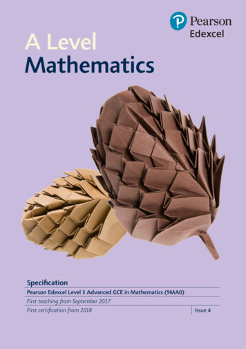
52those observed with bare human fingers, but the changes incapacitance with human fingers in gloves were still measurable. The layer of rubber between the finger and the conductivelayer of the metallized paper increased the distance betweenthe finger and the electrodes (relative to a bare finger touchinga button) and thus, caused a reduction in the overall measuredcapacitance. The finger-portion of a glove filled with an aqueoussolution (deionized water in one case and 150 mM NaCl inanother) also registered responses with the system shown inSI Video 1. For both cases (glove filled with deionized waterand glove filled salt water), the apparent change in capacitancewas less than that with a gloved finger. The reduced change incapacitance may have been from the effective thickness of theglove being greater than that of human skin, reduced conductivity of the aqueous solution, or increased resistance in thepath to electrical ground through the liquid-filled portion of theglove. In contrast to a liquid-filled glove, an air-filled glove registered almost no observable change in capacitance when pressedagainst a key (i.e., capacitive buttons would rarely trigger aresponse by lighting an LED). We attribute these spurious readings to the accumulation of surface charge on the outer surfaceof the glove.Vacumet Corporation evaporates approximately 0.05 g/m2of aluminum onto papers of different thicknesses. Assuming adensity of 2700 kg/m3 for aluminum, the thickness of the layerof evaporated aluminum is less than 20 nm. The two gradesof metallized paper used in this work have specified averagethicknesses and ranges of 56 6 μm and 137 5 μm. Thesespecified thicknesses include paper, coatings of polymer, andevaporated aluminum (see SI Figure 1). By measuring the electrical resistance of different cut sheets of metallized paper, weestimate the average thickness and standard deviation of theevaporated aluminum to be 13 2 nm (see SI Figure 2).Figure 1A-D show the configuration for keys based on coupling between a finger and a parallel-plate capacitor with twolayers of metallized paper. To fabricate two-layered buttons,we etched the traces and cut out the overall dimensions of thesheets of metallized paper using a laser cutter. Once cut, weused double-sided tape (Indoor Carpet Tape from 3M) to holdthe pieces of metallized paper together. We brushed on silverconductive adhesive (Silver Conductive Adhesive 503 fromElectron Microscopy Sciences) to connect traces or tabs on themetallized paper electrically with external electronics throughconductive pads or wired leadsTo measure the changing effective capacitance of the buttonsand demonstrate interactive applications using paper-basedtouch pads, we used the Arduino platform (UNO and MEGA2560). Arduino is a microprocessor-based system with opensource hardware and software for signal processing and computation (see http://www.arduino.cc/). The Arduino platformhas also demonstrated its utility for applications with flexibleor wearable electronics.[20] The Arduino is capable of applyinga step input to a resistor and capacitor in series and measuringthe time required for the potential on the capacitor to reach2 V (see an example at http://arduino.cc/it/Tutorial/CapacitanceMeter and the Supporting Information for code used inSI Video 1). Using this measured time, it is possible to estimatean “RC” time constant and calculate an effective capacitance fora circuit with a known resistance (see SI Figure 3). The typicalwileyonlinelibrary.comresistance for the resistor placed in series with a button was100 kΩ or 1 MΩ. To buffer the potential across the capacitoragainst the impedance of the inputs leading to the Arduino,we used an operational amplifier (LM324) with unity gain. Wealso used a demultiplexing chip (TI CD4067BE 1:16) addressedwith four binary outputs to measure the responses of 10 to48 individual buttons with only one to three electrical inputs.The Arduino-based system and accompanying electronicsrequired about 0.4 W, even though an estimate for the powerrequired for an individual button of 100 pF is 250 nW (see SIfor both estimates).At this point, the electronics for detecting changes in capacitance are neither mechanically compliant nor inexpensiveenough to be considered disposable after a single use. Thepackaged electronics might plausibly be multiple-use with onlythe paper-based system being disposable. It is also conceivablethat the electronics could be made inexpensive enough throughmass-production and conventional techniques for fabricatingsemiconductor-based circuits (e.g., disposable RFID tags andcell phones are representative efforts to produce low-cost, complex electronic systems). To make the required circuits flexible,DuPont Pyralux or the metallized paper itself might serveas a flexible substrate. Nevertheless, we envision applications,which might use reusable electronics for interfacing the disposable touch pads with standard protocols for communicationwith personal computers or commercial electronic databases(e.g., a small box with reusable electronics for sensing andwireless transfer of data might ship multiple times with distinctdisposable touch pads and packaging).To test our touch pads, we constructed single buttons(Figure 2). One button consisted of parallel plates (Figure 2A andB), while the other button consisted of a single layer of metallized paper with etched traces to form inter-digitated electrodes,or macroscopic buttons that were easy to touch (Figure 2Dand E). We mounted the buttons to a manila folder withdouble-sided tape, connected the electrical leads of the buttonsto an Arduino-based system, and used the serial output fromthe Arduino to log data on a laptop computer. Figure 2C and Fshow the measured effective capacitances in a box plot–basedon the time required for the potential across the capacitivebutton in series with a resistor of 1.01 MΩ to reach 2 V with astep input of 5 V–measured over five seconds of sampling forseven untouched buttons and seven touched buttons with anindex finger from a single user. The touch button with a singlesheet of metallized paper was more sensitive than the touchbutton with two sheets (see SI for more details). Touch buttonsin a single sheet are also easier to construct than touch buttonsin a two-layer configuration (i.e., no need to align and bond twolayers of metallized paper to each other).To demonstrate the functionality of the touch button inFigure 2D, we pressed the button shown over 2000 times, and itcontinued to function reproducibly without exhibiting drift (i.e.,it was not necessary to adjust the threshold of detection. Thatsaid, we have implemented a scheme for other touch pads withmoving averages for the thresholds on the Arduino to ensureproper responses over extended periods of time (see http://www.arduino.cc/en/Tutorial/Smoothing and included code forSI Video 1 in the Supporting Information). We also measuredthe response of the button to hundreds of presses with a bare 2012 WILEY-VCH Verlag GmbH & Co. KGaA, WeinheimAdv. Mater. 2012, 24, 2850–2856
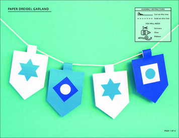
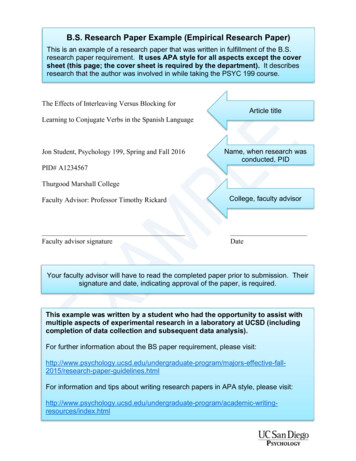
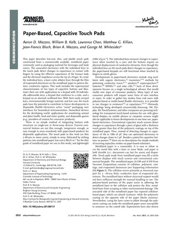
www.advmat.dewww.MaterialsViews.comAdv. Mater. 2012, 24, 2850–2856 2012 WILEY-VCH Verlag GmbH & Co. KGaA, Weinheimwileyonlinelibrary.comCOMMUNICATIONan effective capacitance of 78 pF. Figure 3Cand D show the distribution of peak values inmeasured capacitance during each press. Thetouches with a finger in a gloved hand eliciteda much smaller change in capacitance thanthat observed with a bare finger, and futureimprovements in electronics might improvesensitivity to gloved fingers.To make a keypad with ten buttons(Figure 4), we ablated lines in a piece ofVacumet A-238 (thickness of 60 μm) to formconductive traces and inter-digitated regionsfor ten separate keys. After ablating the linesin the metallized paper, we attached thekeypad to a manila folder with double-sidedtape. To connect the keypad to external electronics, we attached 30-gauge wire to eachof the contact pads (ten contact pads for thekeys and one contact pad for the ground)with conductive paste. To address the separate keys, we used an input and five outputs(one output supplied a stepped signal to theRC circuits and the other four addressed ademultiplexer) on the Arduino. The steppedsignal from the Arduino went throughthe same resistor for all ten keys but wentthrough a separate capacitive region as dictated by a 1:16 demultiplexer (TI CD4067BE).Figure 4C shows measurements taken whena gloved finger touched each key individually, touched keys “0” and “1” simultaneously,and touched keys “1” and “2” simultaneously.With another 10-button keypad mounted to apiece of plastic (see SI Video 1), more than25 different people were all able to trigger theappropriate LEDs to respond with the touchof their bare fingers.To demonstrate the fabrication of a threedimensional keypad from a two-dimensionalFigure 2. Capacitive buttons fabricated with metallized paper. (A) The top piece was VacumetA-238 (thickness of 56 μm) with etched lines outlining the touched, active region, and the patterned piece of metallized paper, webottom piece (grey) was Vacumet A-550 (thickness of 137 μm) and served as an electrical ablated lines in a piece of Vacumet A-550ground. Manually cut pieces of double-sided tape bound the two pieces of metallized paper (thickness of 140 μm) and created traces fortogether. (B) Photo of the button shown in A. (C) Box plots for the effective capacitance of the six individual buttons as shown in Figure 5A.button shown in B for two sets (touched with a bare finger and untouched) of seven measure- Then, we gently folded (sharp creases couldments, each lasting five seconds and having more than 660 sampled points (n 660). The cause a break in electrical conductivity) thewhiskers extend 1.5 X the interquartile length dictated by the distance between the top (75thtwo-dimensional pattern around a cube topercentile) and bottom (25th percentile) of the boxes. The horizontal line in the box showsthe median, and the crosses represent outliers. (D) A single piece of Vacumet A–238 etched form the three-dimensional keypad shown inwith inter-digitated fingers forming a button. The greyed region served as electrical ground. Figure 5B and C. Using the Arduino-based(E) Photo of the tested button shown in D. (F) Box plot for the effective capacitance of the electronics and the same demultiplexer usedbutton shown in E for two sets (touched and untouched) of seven measurements, each lasting for the keypad with 10 buttons, the threefive seconds and having more than 490 points (n 490). The attributes of the box plot are the dimensional keypad detected touches withsame as those in C, except the median is at the top of the box for the untouched cases.either bare or gloved fingers and lit corresponding LEDs (see SI Video 2).finger and a gloved finger (nitrile-based glove from KimberlyThe paper-based touch pads described in this work may beClark). Figure 3 shows some of the measurements taken withuseful as active packaging to prevent theft of the contents ofthe Arduino-based system after the button had already receivedcontainers. To demonstrate a possible implementation (seemore than 1000 presses. The red crosses shown in Figure 3AFigure 6 and SI Video 3), we attached a piece of metallizedand B indicate when the Arduino-based system detected apaper (thickness of 60 μm) with a 10-button keypad and twochange in the state of the button relative to a fixed threshold ofLEDs to a cardboard box with double-sided tape (Figure 6A and2853
gure 3. Measured changes in capacitance for the capacitive buttonshown in Figure 2D after the button had already experienced more than1000 touches. (A) Measurements taken with a bare finger touching thebutton. The ticks show when the electronic system registered a capacitance greater than or equal to the threshold of 78 pF. The red baselineshows the threshold set at 78 pF. (B) Measurements taken with a glovedfinger and the same threshold (red baseline) shown in A. (C) The distribution (general extreme value) of peak capacitances measured during335 presses of the button with a bare finger. The data had a minimummeasured peak at 490 pF. (D) The distribution (normal) of peak capacitances measured during 504 presses of the button with a gloved finger.The mean was 120 7 pF ( 1 standard deviation) for 504 presses, andthe minimum peak measured was at 93 pF.B). The keypad served as the user interface to arm or disarm analarm “built” into the box.When armed, the LEDs were off. Opening the top lids onthe box caused a decrease in the capacitance between the two2854wileyonlinelibrary.comFigure 4. Touch pad with 10 keys that produced measurable changesin capacitance when touched with a bare or gloved finger. (A) Thesingle layer (105 mm 116 mm) comprises discrete keys (17 mm 19 mm) with metallized traces leading to contact pads for connectionto the Arduino-based system. (B) Photo of the completed keypad beingtouched with two gloved fingers on key “2” and key “8”. (C) Measuredresponses at each of the 10 buttons to touches with a gloved finger. Thechange in capacitance was greater with a bare finger than that measuredwith a gloved finger.pieces of metallized paper taped to the lids (capacitive switch).This decrease in capacitance, unlike the increases experiencedby the buttons when touched with a finger, triggered the alarm,sounded a buzzer, and lit up both LEDs on the metallizedpaper. For purposes of demonstration, closing the lids causedthe alarm to stop sounding.To disarm the alarm, the user entered a numeric code bytouching the keys on the keypad. With every press of one of thekeys, the blue LED would flash to provide visual feedback to theuser. To demonstrate the functionality of all the keys in SI Video3, we set the password to “0,1,2,3,4,5,6,7,8,9”. When disarmed, 2012 WILEY-VCH Verlag GmbH & Co. KGaA, WeinheimAdv. Mater. 2012, 24, 2850–2856
gure 5. Paper-based touch pad fixed to a cube. (A) Layout for sixbuttons—one button for each face. Each edge of the cube has a lengthof 38 mm. (B) Image and associated output for a bare finger touchingthe button on face number “2”. (C) Image and associated output for agloved thumb and index finger making simultaneous contact with buttons number “5 and “2”.the electronics lit the green LED, and opening the box did nottrigger the alarm. To arm the alarm from the disarmed state, auser hit any button on the keypad, and the LEDs returned to anunlit state.Capacitive sensing and metallized paper provide a low-costsolution for integrating electronic interfaces with paper-basedproducts. The paper-based keypads in this work are disposable, are as a thin as 60 μm, are simple to etch in a single layerof metallized paper, and can consist of arrays of button. TheAdv. Mater. 2012, 24, 2850–2856Figure 6. An alarmed cardboard box with a paper-based touch pad.(A) On an outside face of the box, the paper-based touch pad had accompanying LEDs to provide feedback to the user. Both LEDs turned on whenthe alarm went off. In the upper left region, there was a capacitive switchto detect whether or not the box was open. (B) The keypad and accompanying LEDs. The keypad had to receive the appropriate code to disable the alarm. The blue LED flashed whenever a button was pushed.(C) Close-up photo of the capacitive switch. (D) All the required electronics inside the box for operating the alarm. The buzzer sounded whenthe alarm went off. 2012 WILEY-VCH Verlag GmbH & Co. KGaA, Weinheimwileyonlinelibrary.com2855
ypads respond to both bare and gloved fingers, but performance is more reliable with bare fingers. Paper that serves as astructural support for very thin layers of metal (approximatethickness of 10 nm) has the potential to provide solutions forfuture developments in sensors and flexible electronics.Supporting InformationSupporting Information is available from the Wiley Online Library orfrom the author.AcknowledgementsThis work was supported by Defense Advanced Research ProjectsAgency (DARPA) N/MEMS S&T Fundamentals Program under grant no.N66001-1-4003 issued by the Space and Naval Warfare Systems CenterPacific (SPAWAR) to the Micro/nano Fluidics Fundamentals Focus(MF3) Center, the Gates Foundation, and DARPA Transient Electronicsgrant no. W911NF-11-1-0254. In addition, we would like to thankSteven A. Morin, Sam Liss, Adam A. Stokes, Jabulani R. Barber, RobertF. Shepherd, and Courtney Hilliard for helpful discussions. We wouldalso like to thank Joe Formosa and Vacumet Corporation for providingsamples of metallized paper.Received: January 11, 2012Published online: April 27, 2012[1] F. Eder, H. Klauk, M. Halik, U. Zschieschang, G. Schmid, C. Dehm,Appl. Phys. Lett. 2004, 84, 2673.[2] R. Martins, A. Nathan, R. Barros, L. Pereira, P. Barquinha, N. Correia,R. Costa, A. Ahnood, I. Ferreira, E. Fortunato, Adv. Mater. 2011, 23,4491.2856wileyonlinelibrary.com[3] S. Yun, S. D. Jang, G. Y. Yun, J. H. Kim, J. Kim, Appl. Phys. Lett. 2009, 95.[4] R. Martins, P. Barquinha, L. Pereira, N. Correia, G. Goncalves,I. Ferreira, E. Fortunato, Appl. Phys. Lett. 2008, 93.[5] A. Russo, B. Y. Ahn, J. J. Adams, E. B. Duoss, J. T. Bernhard,J. A. Lewis, Adv. Mater. 2011, 23, 3426.[6] A. C. Siegel, S. T. Phillips, M. D. Dickey, N. S. Lu, Z. G. Suo,G. M. Whitesides, Adv. Funct. Mater. 2010, 20, 28.[7] D.-H. Kim, Y.-S. Kim, J. Wu, Z. Liu, J. Song, H.-S. Kim, Y. Y. Huang,K.-C. Hwang, J. A. Rogers, Adv. Mater. 2009, 21, 3703.[8] H. Tian, T. L. Ren, D. Xie, Y. F. Wang, C. J. Zhou, T. T. Feng, D. Fu,Y. Yang, P. G. Peng, L. G. Wang, L. T. Liu, ACS Nano 2011, 5, 4878.[9] Z. Weng, Y. Su, D. W. Wang, F. Li, J. H. Du, H. M. Cheng, Adv. EnergyMater. 2011, 1, 917.[10] L. B. Hu, H. Wu, F. La Mantia, Y. A. Yang, Y. Cui, ACS Nano 2010, 4,5843.[11] X. Liu, M. Mwangi, X. Li, M. O’Brien, G. M. Whitesides, Lab on aChip 2011, 11, 2189.[12] M. C. Barr, J. A. Rowehl, R. R. Lunt, J. J. Xu, A. N. Wang, C. M. Boyce,S. G. Im, V. Bulovic, K. K. Gleason, Adv. Mater. 2011, 23.[13] R. K. Kramer, C. Majidi, R. J. Wood, presented at 2011 IEEE International Conference on Robotics and Automation (ICRA), Shanghai,China, May, 2011[14] D. Cotton, I. M. Graz, S. P. Lacour, Sensors Journal, IEEE 2009, 9,2008.[15] A. R. Deangelis, D. B. Wilson, B. A. Mazzeo, US Patent 7,578,195,2009.[16] A. R. Deangelis, B. D. Wilson, B. A. Mazzeo, US Patent 7,395,717,2008.[17] A. R. Deangelis, B. D. Wilson, B. A. Mazzeo, US Patent 7,301,351,2007.[18] R. Hagglund, T. Unander, A. From, P. Wagberg, US Patent App.2007/0018998 A1, 2007.[19] ESD Fundamentals, ESD Association, Rome, NY 2010.[20] L. Buechley, M. Eisenberg, Pe
nitrile gloves fi lled with aqueous solutions. Human fi ngers in gloves (Sterling nitrile powder-free examination gloves from Kimberly-Clark) caused smaller changes in capacitance than Figure 1 . Schematic layouts for two types (A-D and E-H) of capacitive keys made with metal-lized paper.