Transcription
SmartChoiceTMGen II Water Conditioning System CLOCKREGENNEXT Installation, Operation,and Maintenance ManualInstallation, Operation, andMaintenance Manual114 Vista ParkwayAvon, IN 46123(317) 272-6721 (800) 272-5511 2021 New Aqua LLC
Series SC GIIInstallation, Operation,andMaintenance ManualIntroductionWelcome to the Aqua Systems family of customers. Wethank you for placing your confidence in Aqua Systems toassist with your water improvement project. Our goal is toprovide water quality solutions with lasting performance.We are here to ensure the continued successful operation ofyour water treatment system, and we want to hear from youanytime you need assistance.The SmartChoice water conditioning system was designedwith the owner in mind. Most water conditioning productson the market today are designed to be disposable.The SmartChoice was designed to be a lasting appliance that can provide a lifetime of operation. The ExchangeableComponent Maintenance System allows easy and efficient maintenance solutions. Each major part of the SmartChoice isa replaceable component that is easily removed. Although it may be years before the first service is required, this systemoffers you the ultimate in long-term care. All components of the SmartChoice are exchangeable with the factory. You havethe option of exchanging the component yourself, or having an experienced service technician assist in maintenance. Witheither choice, the exchangeable component program ensures precise results and low cost.Each SmartChoice is hand crafted by a skilled technician. The personal attention to detail assures you of the high qualitycraftsmanship Aqua Systems is known for. The SmartChoice is the solution for many common applications. It is also idealfor customized, built-to-suit requirements. The SmartChoice can be tailored as a solution to most any application. Pleasebe sure you let your dealer know if you have any special circumstances, or if you observe anything unusual about the watersupply you are installing the system on.Please review this Installation, Operation, and Maintenance manual for valuable information that will help ensure successfulresults. Supplement manuals are available for specialized filters and custom tailored systems. Service manuals are alsoaccessible on our web site at any time. If you have questions, please feel free to contact the factory or your local dealer.Aqua Systems and our professional dealers are always prepared to assist you.Visit us on the web at www.aquasystems.comOwner InformationOwner Name Serial NumberDate of InstallationDealer NameModel NumberInstaller Name2 2021 New Aqua LLC dba Aqua Systems 114 Vista Parkway Avon, IN 46123
Series SC GIIInstallation, Operation,andMaintenance ManualTable of ContentsOwner Information. 2Introduction. 2How the SmartChoice Works. 4Pre Install Review. 6Requirements for Proper Operation:. 6Location Data. 6Pre Assembly. 7Bypass Operation. 8Installation. 9Softener Placement. 9Brine System Placement. 10Start Up. 12Disinfection:. 12Programming. 12Installer Displays/Settings:. 14User Displays/Settings:. 15Service. 16Parts Diagrams. 19-30Service Guide. 31Drive Assembly. 31Drive Cap Assembly, Main Piston and Regenerant Piston. 32Spacer Stack Assembly. 33Injector Cap, Screen, Injector Plug and Injector. 34Refill Flow Control Assembly or Refill Port Plug. 34Water Meter or Meter Plug. 35Bypass Valve. 35Troubleshooting. 37Troubleshooting. 38 2021 New Aqua LLC dba Aqua Systems 114 Vista Parkway Avon, IN 461233
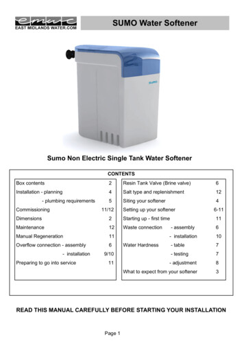
Series SC GIIInstallation, Operation,andMaintenance ManualHow the SmartChoice WorksHeavy Duty System Design: Light Commercial Models The Resin Tank:contains media called resin. The resin attracts andcollects minerals from hardwater. Once the resin issaturated with hardnessminerals it must becleaned and regenerated.Once regenerated, theresin is ready to softenmore water. The performance of a water softener is dependent on two key functions; a resin bed that cleans the water and precisionequipment that cleans the resin. The two most significant elements that differentiate light commercial softeners are thequality of the components and ease of use (setup and service).CLOCKREGENNEXTThe Control Valve: routes the water flow through the system andcontrols the operating cycles. Hard water passes through the resinbed to become soft. During regeneration, water flow is reversed tobackwash which cleans the resin bed. Brine is pulled in and thenrinsed out to regenerate the resin, preparing it to soften more water.The brine tank is then refilled with soft, fresh water for future cycles.Regeneration cycles are based on digital logic, calculating dailywater use and then scheduling a cycle at the preset time, thusmaximizing efficiency over standard controls. Cycles can be customprogrammed making the SmartChoice adaptable to virtually anyapplication.Brine tanks areavailable in a varietyof sizes to match thecapacity needed foreach size of resin tank/system capacity.Historically, resin tankconstruction was metal.To eliminate destructivecorrosion, moderntanks are made with amolded liner that iswrapped in fiberglassfor exceptional strengthand durability.Safety shut offprovides total brinesystem shut downto protect againstbrine overflow.Resin is madeof cross-linkedpolystyrene toprovide a longlife of softeningcapacity.The riser distributorcollects the water thathas been softened in the service cycle androutes it to the outlet of the control valve.It also aids in lifting and “fluffing” the resinbed for the brining cycle.4Salt shelf (24” & 30”brine tanks) permitsuse of almost any typeof salt and eliminatesbridging and mush bykeeping the salt dry inthe larger brine tanks.The Brine System: stores salt and water to make brine which isused for regenerating the resin. Resin can be regenerated withsodium from sodium chloride (softener salt) or potassium frompotassium chloride. 2021 New Aqua LLC dba Aqua Systems 114 Vista Parkway Avon, IN 46123
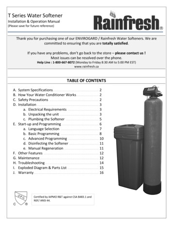
Series SC GIIInstallation, Operation,andMaintenance ManualHow the SmartChoice WorksResin Scrubber Vortech * Design: VT Models The Resin Tank:contains media called resin. The resin attracts andcollects minerals and ironfrom hard water. Oncethe resin is saturated withhardness and iron minerals it must be cleaned andregenerated.Once regenerated, theresin is ready to softenmore water. The performance of a water softener is dependent on two key functions; a resin bed that cleans the water and precisionequipment that cleans the resin. The three most significant elements that differentiate one softener from another are thevolume of resin, the type of control valve, and the backwash system.CLOCKREGENNEXTThe Control Valve: routes the water flow through the system andcontrols the operating cycles. Hard water passes through the resinbed to become soft. During regeneration, water flow is reversed tobackwash which scrubs the resin bed. Brine is pulled in and thenrinsed out to regenerate the resin, preparing it to soften more water.The brine tank is then refilled with soft, fresh water for future cycles.Regeneration cycles are based on digital logic, calculating dailywater use and then scheduling a cycle at the preset time. Cyclescan also be predetermined and programmed in the control if sodesired. Also, in problem waters, the control is programmed tobackwash the resin twice resulting in increased iron removal.Resin tanks can beexposed or coveredwith a jacket orinsulated cabinet.Brine tanks areavailable in a varietyof sizes to fit in almostany space and are blowmolded for strengthand durability.Historically, resin tankconstruction was metal.To eliminate destructive corrosion, moderntanks are made with amolded liner that iswrapped in fiberglassfor exceptional strengthand durability.Safety shut offprovides total brinesystem shut downto protect againstbrine overflow.Pre-Fill brining allowsthe salt to always staydry except for the amoutneeded during thenregeneration cycle.After the regeneration,the salt is dry until thebeginning of the nextregeneration.Resin is madeof cross-linkedpolystyrene toprovide a longlife of softeningcapacity.The Vortech bottomplate distributor.Unlike conventional distributors, the Vortech significantly improvesthe efficiency of the system by reducing backwash rates by at least30% and reducing pressure loss through the system up to 40%. Theinnovative design of the bottom plate achieves a much greater resincleaning ability coupled with lower water use yet is gentle on theresin, thus extending its service life.The Brine System: stores salt and water to makebrine which is used for regenerating the resin.Resin can be regenerated with sodium from sodiumchloride (softener salt) or potassium frompotassium chloride.* Vortech tanks are manufactured by ENPRESS LLC 2021 New Aqua LLC dba Aqua Systems 114 Vista Parkway Avon, IN 461235
Series SC GIIInstallation, Operation,andMaintenance ManualPre Install ReviewRequirements for Proper Operation:Water Pressure: The system will operate ona minimum of 20 psi and a maximum of 125 psi.Flow Rate: A minimum of 5 gallons per minuteis required for proper system operation. If lessthan 5 gpm is available, consult with your dealer for customsettings or configurations.Tips:Salt: Using a clean grade of salt will helpeliminate the need to clean out the brine tank.If the water supply contains iron, the use of aniron inhibiting salt can help the water quality.Ask your dealer for the recommendedsalt for your system.Water Temperature: The range of watertemperature to operate this system on is 40º Fto 110º FBypass: When installing a water conditioner,it is required that the system have a bypassin place to be able to shut off the conditionerwithout turning off the water supply.Drain: A drain should be within 20’ of the system using 1/2”tubing. Over 20’ should be 3/4” tubing. Maximum overheadheight is 8’. Consult your dealer for any drain over 30’Freezing: The water conditioner and thedrain line must be protected from freezingtemperatures.Electricity: An uninterrupted 110 volt A.C. source is requiredto operate this system. Note: Make sure electrical source isnot on a timer or a switch.Sand: If sand or sediment is present in thewater supply, a sediment filter should be installed ahead of the system.Location DataSizing Information:Calculation for Hardness Setting :Bypassed Hard Water Lines:Hardness gr./gal.Hardness in gpgRear Outside SpigotIronppmpHIron in ppmx 4 (multiply x 4)No. in FamilyKitchen ColdOtherOtherInlet Line SizeFront Outside SpigotTotal CompensatedHardness(add adj. iron and hardness)Use the Total CompensatedHardness number for Hardness Settingin start up programming. (Page 14)6 2021 New Aqua LLC dba Aqua Systems 114 Vista Parkway Avon, IN 46123
Series SC GIIInstallation, Operation,andMaintenance ManualPre Assembly1. Carefully remove system from carton and inspect. Thesystem box should contain:a. Softenerb. Bypass Valvec. Plumbing Connectorsd. Owner’s Manual2. Remove brine system from carton and inspect. The boxshould contain:Tip:Take a moment to fill out the informationsections in the Owner’s Manual. It canbe a valuable tool in the future to have allthe installation data available to answerany questions.a. Brine Tank assy.b. 5 ft. Poly Brine Line3. Attach the bypass to the unit. (see figure 1 )The bypass valve easily connects to the control valve bodyusing nuts that only require hand tightening. Hand tightennut connections between control valve and fittings, controlvalve and bypass valve, and bypass valve and installationfittings. The split ring retainer design holds the nut on andallows load to be spread over the entire nut surface areareducing the chance for leakage. The split ring design, incorporated into the bypass, allows approximately 2 degreesoff axis alignment to the plumbing system. The bypass isdesigned to accommodate minor plumbing misalignmentsbut is not designed to support the weight of a system orthe plumbing.4. Attach the selected connection fitting kit to the bypass.The nuts, split rings, and o-rings install the same as thebypass. (see figure 2 ) Connection kit sizes available are1” NPT PVC, 3/4” or 1” Solvent Weld, 1” Sweat Copper,3/4” Sweat Copper, and other various sizes & types. Seeyour dealer if a specific kit is desired other than the listedkits.1” PVC MaleOptional Salt Monitor:If the optional Salt Monitor is beinginstalled at this time, refer to the included instructions with the monitor forinstallation and setup of the components.Tip:Do not use Vaseline, oils, or any petroleum lubricants on o-rings. A siliconlubricant may be used on black o-ringsonly.Caution:3/4” or 1” PVCSolvent Weld3/4” Copper Sweat1” Copper Sweatfigure 1figure 2Connection portson back of controlvalveWhen assembling the inlet/outlet fitting kit,connect the fittings to the plumbing first.Then attach the nut, split ring, and o-ringafter the fitting has cooled or dried. Heatfrom soldering or PVC glue solvents maydamage the nut, split ring, or o-ring. 2021 New Aqua LLC dba Aqua Systems 114 Vista Parkway Avon, IN 461237
Series SC GIIInstallation, Operation,andMaintenance ManualBypass OperationThe bypass valve is typically used to isolate the control valve from the plumbing system’s water pressure in order to perform control valve repairs or maintenance. The SmartChoice bypass valve is particularly unique in the water treatmentindustry due to its versatility and state of the art design features. The 1” full flow bypass valve incorporates four positionsincluding a diagnostic position that allows service work on a pressurized system while still providing untreated bypassedwater to the facility or residence. Its completely non-metallic, engineered material design allows for easy access and serviceability without the need for tools.1.Normal Operation Position: The inlet and outlet handles point in the direction offlow indicated by the engraved arrows on thecontrol valve. Water flows through the controlvalve during normal operation and this position also allows the control valve to isolatethe media bed during the regeneration cycle.(see figure 1)2.Bypass Position: The inlet and outlet handles point to the center of the bypass,the control valve is isolated from the waterpressure contained in the plumbing system.Untreated water is supplied to the plumbingsystem. (see figure 2)figure 1figure 2figure 3figure 43.Diagnostic Position: The inlethandle points in the direction of flow and theoutlet handle points to the center of bypassvalve, system water pressure is allowed tothe control valve and the plumbing systemwhile not allowing water to exit from the control valve to the plumbing. (see figure 3)4.Shut Off Position: The inlet handlepoints to the center of the bypass valve andthe outlet handle points in the direction offlow, the water is shut off to the plumbingsystem . If water is available on the outletside of the softener it is an indication of waterbypass around the system (i.e. a plumbing connection somewhere in the buildingbypasses the system). (see figure 4)8 2021 New Aqua LLC dba Aqua Systems 114 Vista Parkway Avon, IN 46123
Series SC GIIInstallationSoftener Placement1. Find a location with accessibility to:A. The main inlet water supply or pre-plumbed connection pointB. Adequate drain fixture, capable of 5 gallons perminute flowC. Electrical Outlet2. Place unit in the desired location. If the floor is not levelthe unit may be leveled with the built in adjustable base bylightly tapping the unit on the floor.3. There should be a minimum of 12’ of Water Line betweenthe softener and the water heater.4. Before connecting the lines:a. Turn off electric or gas to water heater.b. Turn off main water supply to building and drainoff pressure to all cold water outlets.c. Determine which outlets are to be bypassed andmake provisions to connect them before the softener.d. It is highly recommended to provide an inlet shutoff valve near the unit.e. The inlet water line should be a minimum of 3/4”in size. If yours is smaller, consult your dealer forrequired adjustments.5. With the above considerations, connect the water line tothe inlet of the unit which is designated by a gray arrowon the bypass pointing toward the control valve.6. Connect the outlet which is designated by a gray arrowpointing away from the control valve to the water line thatfeeds the rest of the building.7. If the plumbing system is metal pipe (ex. - copper), installa jumper ground wire and grounding clamps between theinlet and outlet pipes to retain continuity of the plumbing.Installation, Operation,andMaintenance ManualAll plumbing must be done inaccordance with localplumbing codes.Caution:The control valve, fittings and/or bypass are designed to accommodate minor plumbing misalignments but are not designed to support the weightof a system or the plumbing.Do not use Vaseline, oils, other hydrocarbonlubricants or spray silicone anywhere. A siliconlubricant may be used on black o-rings but is notnecessary. Avoid any type of lubricants, including silicone, on red or clear lip seals.The nuts and caps are designed to be unscrewedor tightened by hand or with the special plasticwrench. If necessary, pliers can be used to unscrew the nut or cap. Do not use a pipe wrench totighten or loosen nuts or caps. Do not place screwdriver in slots on caps and/or tap with a hammer.Do not use pipe dope or other sealants onthreads. Teflon tape must be used on the threadsof the 1” NPT elbow or the 1/4” NPT connectionand on the threads for the drain line connection.Teflon tape is not necessary on the nut connectionor caps (if not using the connection nut) becauseof o-ring seals.When assembling the installation fitting package(inlet and outlet), connect the fitting to the plumbing system first and then attach the nut, split ringand o-ring. Heat from soldering or solvent cements may damage the nut, split ring or o-ring.Solder joints should be cool and solvent cementsshould be set before installing the nut, split ringand o-ring. Avoid getting primer and solvent cement on any part of the o-rings, split rings, bypassvalve or control valve.Tip: If there is a three way bypass in the existing plumbing, inspect itto make sure the bypass valve shuts off 100% when closed. 2021 New Aqua LLC dba Aqua Systems 114 Vista Parkway Avon, IN 461239
Series SC GIIInstallation, Operation,andMaintenance ManualInstallation8. Connect the drain on the softener to an approved air gapdrain. When using 5/8” poly tubing for the drain line,connect the nut to the line as illustrated in figure 1. If copperline is used, be sure to pre-sweat and cool pipe and fittingsbefore attaching to drain fitting on unit.Caution:Make sure all plumbing connectionsare completed before turning on water.Check for and repair any leaks beforeproceeding with start up of system.Brine System Placement9. Find a smooth, level location clean and free of debris forthe brine system. Locate and place the brine systemwithin 15 feet of the softener (15 feet maximum brineline distance). Connect the brine line to the brine tank andthe softener with the supplied 3/8” O.D. poly tubing (seefigure 2 ).10. Connect overflow fitting with 5/8” poly tubing and run toa floor drain or through the floor to the crawl space.Note: This is a gravity drain and must run at a downwardslope from the fitting. It would only be used in the eventof a malfunction in the system.Drain Fittingfigure 1Insert untilfully seatedTurning on Water:Brine Fittingfigure 21. With all plumbing connections made, make sure thebypass is in the “bypass” position (see figure 3 ). Slowlyturn on the water supply valve until lines are pressurized.At a nearby faucet, turn on cold water and let it run for 2 3 minutes to flush debris (solder, pipe tape, glue, etc.) fromthe plumbing. Check for water leaks. If any leaks arefound, repair them immediately before proceeding.2. After confirming no leaks exist, proceed to start upinstructions on page 12.figure 310 2021 New Aqua LLC dba Aqua Systems 114 Vista Parkway Avon, IN 46123
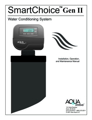
Series SC GIIInstallation, Operation,andMaintenance ManualInstallationCity Water Installation:Water HeaterOutlet toHouseOutletFlowTreated WaterWater SoftenerHard Water BypassInlet toSoftenerBrine SystemConnect BrineTank Line HereAirGapConnect DrainLine Here000032Water MeterTop View ofControl ValveWell Water Installation:Note:Minimum of 12 feetof line betweensoftener and waterheaterNote:Overflow gravity drain - Connect hoseand run to floor drain or through floorto crawl space. This is used only inthe event of a malfunction.Water SoftenerWater HeaterHard Water BypassTreated WaterPump LinePressure TankBrine SystemAirGap 2021 New Aqua LLC dba Aqua Systems 114 Vista Parkway Avon, IN 4612311
Series SC GIIInstallation, Operation,andMaintenance ManualStart UpPut Unit into Service (Start Up):1. Add 2” of water to the brine (if there is no salt shelf which isnormal). Add 6” of water to the brine tank if tank has a saltshelf, about 1” above shelf. Disregard this step if this is a backwashing filter.2. Plug the transformer into a 110 volt receptacle. The controlwill place itself in the”Softening” (or “Filtering”) mode andflash 12:00 on the display.Note:Make sure that the electrical outlet usedis an uninterrupted outlet (such as outletthat is operated by a switch).All electrical connections must be connectedaccording to local codes.3. Set the current time of day. (see page 13 )4. Push and hold the “REGEN” button for 3 seconds. Thesystem will advance to the “FILL” position.5. Push “ REGEN” button and release. The control willadvance to the “SOFTENING” position, which is a pause.6. Push “ REGEN” button and release. The control willadvance to the “BACKWASH” position.Note:When pushing the “REGEN” button toadvance cycles, let the control reach thenext cycle before pushing the “REGEN”button again.Disinfection:7. Slowly open the inlet to the bypass. (see page 8, figure 3 )8. Water will run to the drain. Let it run 5 minutes or until thethe water to drain is clear. If filter, skip steps 9-11.9. Push “ REGEN” button and release. The control willadvance to the “BRINE” position. Let cycle run for minuteto confirm the control is drawing (has a suction at the brineelbow).10. Push “ REGEN” button and release. (see note at right) Thecontrol will advance to the next cycle. Advance through cyclesusing the “REGEN” button until the control reaches the service(“SOFTENING”) position.11. When the control has reached the service position, fill thebrine tank with salt. Open the outlet handle on bypass (seepage 8, figure 1).12. Let cold faucet run for 2-3 minutes then test for soft water.13. Next, run a hot faucet fully open until it runs cool to fill thewater heater with soft water.14. Proceed to the Programming instructions. After programming, the system should be disinfected. For filter disinfection,call your dealer for instructions.12The materials of construction of the modern waterconditioner will not promote bacterial growth, norwill these materials contaminate a water supply.However, the normal conditions that exist duringshipment, storage and installation make it advisableto disinfect a conditioner after installation, before theconditioner is used to treat potable water. In addition, during normal use, a conditioner may becomefouled with organic matter, or in some cases, withbacteria from the water supply. Therefore everyconditioner should be disinfected after installation,some will require periodic disinfection during theirnormal life.To Disinfect the System:1. Add 1.2 fluid ounce of 5.25% sodium hypochlorite solution (unscented household bleach; Clorox, Bo Peep,etc.)for each cubic foot of resin to the brine well of the brinetank. ( the 4” tube with a cap on it inside of the brinetank)2. Press “REGEN” for 3 seconds to start a normal regenerattion. Allow the system to complete the regeneration. 2021 New Aqua LLC dba Aqua Systems 114 Vista Parkway Avon, IN 46123
Series SC GIIInstallation, Operation,andMaintenance ManualProgrammingSet Time of Day:1. Press “SET CLOCK”2. Current Time (hour): Set the hour of the day using “Up” or “Down”buttons. AM/PM toggles after 12. Press “NEXT” to go to step 3.3. Current Time (minutes): Set the minutes of the day using “Up” or “Down”buttons. Press “NEXT” to exit Set Clock. Press “REGEN” to return toprevious step.Note:If the power goes out, the current time willremain correct as long as batter has sufficientcharge (up to 2 years). If the battery expires,the screen will state “Low Battery”. The batReturn toNormal Operationtery should be replaced and the time reset. Allother programming will be retained.Displayed when battery voltage is low.Display alternates with previously selected display.Energy Saver Feature with Gen II Enhanced Electronics:The Energy Saver function manages the display backlight in the Gen II control. An option is available onthe enhanced circuit boards. The option is Energy Saver / AUTO. This feature combines the benefit ofthe Energy Saver, that turns the backlight off when buttons are not in use, but it will activate the backlightwhen a User Alert Screen is triggered. Red Screen User Alerts, which include Salt Monitoring, ServiceAlarm and Error Screens will activate the Display light, and keep it on until the Alert condition is cleared. 2021 New Aqua LLC dba Aqua Systems 114 Vista Parkway Avon, IN 4612313
Series SC GIIInstallation, Operation,andMaintenance ManualProgrammingInstaller Displays/Settings:1. Press “NEXT” and “Up” simultaneously for 3 seconds.2. Hardness: Set the amount of hardness in grains per gallon of hardness. Usethe “Total Compensated Hardness” number from page 6. Use the “Up” and“Down” buttons to set the hardness number. Press “NEXT” to go to the nextstep.3. Day Override: Maximum allowable days between regenerations. Can be set to“OFF” to regenerate based only on gallons used. If a number is set (1-28),regeneration is based on gallons unless the specified number of days isreached. The systems then regenerates at the programmed time and thegallon capacity is reset. Press “NEXT” to go to the next step.4. Day Override Regeneration Time (hour): Set the hour of day for regenerationusing the “Up” or “Down” buttons. Press “NEXT” to set minutes. Not shown ifDay Override is set to “OFF”.5. Day Override Regeneration Time (minutes): Set the minutes of day for regeneration using the “Up” or “Down” buttons. Press “NEXT” to set energy saver.6. Reg
collects the water that has been softened in the service cycle and routes it to the outlet of the control valve. It also aids in lifting and "fluffing" the resin bed for the brining cycle. The performance of a water softener is dependent on two key functions; a resin bed that cleans the water and precision equipment that cleans the resin.