Transcription
Operating and Maintenance Manual Model 43AAV34-AC 5/2/18MPSMIDWESTPRESSURESYST E M STechnical ManualManufacturer - Midwest Pressure Systems, Inc.Model 43AAV34-ACGas Pressure BoosterCustomer Order Number Serial Number -Prepared May 2, 2018Midwest Pressure Systems, Inc. 850 Transport Drive Valparaiso, Indiana 46383 USAPhone 219-462-0070 Web Site www.midwestpressuresystems.comPage 1
Operating and Maintenance Manual Model 43AAV34-AC 5/2/18Table of Contents1. Design Specifications2. Materials of Construction and Torque Specifications3. Flow Curves4. Boost Cylinder Operation5. Drive Air System Operation6. Installation7. Startup8. Operation9. Maintenance & Warranty10. General Arrangement Drawing11. Booster Assembly DrawingMidwest Pressure Systems, Inc. 850 Transport Drive Valparaiso, Indiana 46383 USAPhone 219-462-0070 Web Site www.midwestpressuresystems.comPage 2
Operating and Maintenance Manual Model 43AAV34-AC 5/2/18Page 31 Design SpecificationsMidwest Pressure Systems, Inc. (MPS) air pressure boosters are designed for ease of operation andmaintenance. Experience has shown that an MPS booster will normally provide years ofsatisfactory performance with minimal maintenance. Carefully review this manual which isdesigned to provide information on installation, start up, operation and maintenance. If you havequestions, please contact Midwest Pressure Systems, Inc.Booster design meets these ATEX specifications:0575II 2 G T4Designed in accordance with ASME Boiler and Pressure Vessel Code, Section VIII, Division 1Model 43AAV34-AC Engineering SpecificationsMaximum gas discharge pressure - psi (bar)Gas temperature range - F ( C)493 (34)-15 to 250 (-26 to 121)Maximum cycle rate - cycles per minute (Note 1)Gas displacement per cycle - cf (liters)Maximum gas displacement - cfm (liters per minute)100.038 (1.07)3.8 (107)Pressure boost (multiple of drive air pressure) (Note 2)1.4Gas inlet and discharge connections FNPT1/4Seal vent connection FNPT1/8Maximum drive pressure - psi (bar) (Note 3)Air temperature range - F ( C)Air displacement per cycle - cf (liters)Maximum air displacement - cfm (liters per minute)125 (8.6)32 to 167 (0 to 75).069 (1.95)6.9 (195)Drive air inlet connection FNPT1/2Drive air exhaust connection FNPT1/2Drive air cylinder bore diameter - inches (millimeters)4 (102)Gas boost cylinder bore diameter - inches (millimeters)3 (76.2)Piston rod diameter - inches (millimeters).625 (15.9)Stroke - inches (millimeters)4.8 (122)Weight - pounds (kilograms)31 (14)Ambient Temperature - F ( C) (Note 4)-15 to 167 (-26 to 75)Note 1: A cycle consists of a forward and reverse stroke.Note 2: This is a nominal operating pressure boost ratio, not the maximum pressure boost ratio.Note 3: Nitrogen may also be used for the drive gas.Note 4: Where ambient temperatures fall below 0 C (32 F) a heater is required for the drive air.Midwest Pressure Systems, Inc. 850 Transport Drive Valparaiso, Indiana 46383 USAPhone 219-462-0070 Web Site www.midwestpressuresystems.com
Operating and Maintenance Manual Model 43AAV34-AC 5/2/18Page 42 Materials of Construction and Torque SpecificationsProcess gas wetted materialsAnodized Aluminum and stainless steelPneumatic drive materials exposed to the environmentAnodized aluminum for excellent general environmental corrosion resistanceExternal bolts, nuts, and washers18-8 SS for excellent marine and general environmental corrosion resistanceDynamic seal materialCarbon-fiber-filled Teflon piston rings and rod sealsGas wetted static sealsVitonAir drive sealsBuna-NMaterial specifications for individual components are listed in Sections 10 and 11.Fastener Torque Specifications!This booster utilizes high strength fasteners. Replacement fasteners must be of the same grade andmaterial or the booster could fail and cause a fire, explosion or toxic gas release.Fastener DescriptionSizeInch TPITypeTorqueLb-Ft (N m)Piston Rod Nuts3/8-16 UNC18-8 SS hex head locknut 11/16 wrench20 (27)1” and 7” Long Screws3/8-16 UNC18-8 SS socket head cap screw 5/16 wrench15 (20)Air Manifold Mounting Screws10-32 UNC18-8 SS socket head cap screw 5/32 wrench3.3 (4.5)Control Valve Mounting Screws1/4-20 UNC18-8 SS socket head cap screw 3/16 wrench7.9 (10.7)Midwest Pressure Systems, Inc. 850 Transport Drive Valparaiso, Indiana 46383 USAPhone 219-462-0070 Web Site www.midwestpressuresystems.com
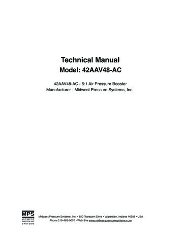
Operating and Maintenance Manual Model 43AAV34-AC 5/2/18Page 53 Flow CurvesThe graph below shows the performance curve of the 43AAV34-AC air pressure booster. In the graph, the drive and supplypressures are equal. Use this curve to size the 43AAV34-AC air pressure booster for a given application.Model 43AAV34 Flowrate versus Discharge Pressure - Air Pressure Boosting300Discharge Pressure in psi2502001501005003691215Flowrate in SCFM60 psi supply70 psi supply80 psi supply90 psi supply100 psi supplyMidwest Pressure Systems, Inc. 850 Transport Drive Valparaiso, Indiana 46383 USAPhone 219-462-0070 Web Site www.midwestpressuresystems.com18
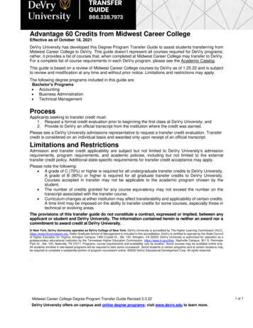
Operating and Maintenance Manual Model 43AAV34-AC 5/2/18Page 63 Flow CurvesThe graph below shows a performance curve of the 43AAV34-AC air pressure booster. In the graph, the drive air pressure isheld constant at 80 psi and process air supply pressures vary as shown below. Use this curve to size the 43AAV34-AC airpressure booster for a given application.Model 43AAV34 Flowrate versus Discharge Pressure - Drive air pressure is 80 psi250Discharge Pressure in psi2001501005003691215Flowrate in SCFM60 psi supply70 psi supply80 psi supply90 psi supply100 psi supplyMidwest Pressure Systems, Inc. 850 Transport Drive Valparaiso, Indiana 46383 USAPhone 219-462-0070 Web Site www.midwestpressuresystems.com18
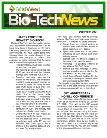
Operating and Maintenance Manual Model 43AAV34-AC 5/2/18Page 74 Boost Cylinder OperationThe piston in the drive cylinder is attached to the piston in the boost cylinder. As the drive piston reciprocates, it compresses the gas inthe boost cylinder. The controls which cause the drive cylinder to reciprocate are described in Section 4 entitled, “Drive Air SystemOperation”.The boost cylinder is double-acting, i.e., it pulls gas in on one side while pumping it out on the other. The maximum pressure boost isequal to the drive piston area divided by the boost piston area multiplied by the pressure feeding the drive cylinder. At this maximumboost pressure, the forces in the booster are balanced and the booster stalls. This booster has a four inch diameter drive piston and athree inch diameter boost piston resulting in an area ratio of 1.77. With an 80 psi air supply it can attain a maximum boost pressure of141 psi. If the gas supply pressure is 80 psi, the maximum discharge pressure would be 221 psi and the booster would stall. When thedischarge pressure drops below 221 psi, the booster will start pumping.An external manifold connects the two inlet check valves and an external manifold connects the two discharge check valves. There isone inlet and one discharge gas connection. An alternative inlet and discharge connection is plugged. If use of the plugged connectionsis more convenient for piping purposes, the plugs may be removed and installed on the open ports thereby changing the location of theinlet and discharge piping connections.The pistons below are traveling to the right and compressingthe gas in chamber “B” while pulling gas into chamber “A”.GasInletDistance PieceABGasDischargeGasInletBoost CylinderDrive CylinderADistance PieceBGasDischargeBoost CylinderDrive CylinderThe pistons below are traveling to the left and compressingthe gas in chamber “A” while pulling gas into chamber “B”.GasInletDistance PieceDrive CylinderABGasDischargeBoost CylinderGasInletABThe distance piece is designed to ensure that the gas in the boost cylinder is isolated from the air in the drive cylinder.There areGaspiston rod seals at each end of the distance piece,Distanceand the distanceof thePiecebetween the rod seals is greater than the stroke lengthDischargebooster. Consequently, the section of piston rod which penetrates the driveBoostcylindernever penetrates the boost cylinder and vice versa.CylinderDrive CylinderThere is one 1/8 NPT gas vent port with a breather installed. Any air that leaks past the air seal, or gas which leaks past the gas siderod seal will flow out of this vent. The unit is supplied with breathers which vent to atmosphere.Midwest Pressure Systems, Inc. 850 Transport Drive Valparaiso, Indiana 46383 USAPhone 219-462-0070 Web Site www.midwestpressuresystems.com
Operating and Maintenance Manual Model 43AAV34-AC 5/2/18Page 85 Drive Air System OperationThe sketch below shows the 4-way valve extended to the left. This causes drive air to fill drive cylinder chamber “B” andopens chamber “A” to exhaust. The air piston is driven to the left. The drive air supply also feeds pilot valve “A” andpilot valve “B”. Both of these valves are closed, and the pilot ports at the end of the 4-way valve are open to atmospherethrough breather vent “A” and breather vent “B”. All of the piping connections shown in the sketch are machined into inthe valve manifold and cylinder end caps. There is no external tubing.Drive Air ExhaustDrive Air Supply4-Way ValveValveManifoldPilot Valve BPilot Valve ABreather Vent AAir PistonABBreather Vent BPiston RodDrive CylinderIn the sketch below, the air piston has reached the end of its stroke and opened pilot valve “A”. This closes breather vent“A” and sends pilot air to the left pilot port on the 4-way valve. The 4-way valve shifts to the right, opens chamber “B”to exhaust and supplies drive air to chamber “A”. The air piston moves to the right. When the piston moves off the endcap a spring returns pilot valve “A” to its normal position which closes off the air supply and vents the pilot air from the4 way valve. This process is repeated on the right end of the drive cylinder which causes the air piston to reciprocateautomatically.Drive Air ExhaustDrive Air Supply4-Way ValveValveManifoldPilot Valve BPilot Valve ABreather Vent AAir PistonBDrive CylinderBreather Vent BPiston RodMidwest Pressure Systems, Inc. 850 Transport Drive Valparaiso, Indiana 46383 USAPhone 219-462-0070 Web Site www.midwestpressuresystems.com
Operating and Maintenance Manual Model 43AAV34-AC 5/2/18Page 96 Installation1 Mounting1a The booster has mounting brackets on each end with two 13/32 inchdiameter mounting holes centered on the corners of a 1.9 inch by 20.8 inchrectangle. The booster can be mounted in any orientation using 3/8 inchmounting bolts.2 Air Supply Connection2a The drive air line connection is 1/2 female NPT. The piping should beinstalled to prevent stresses from acting on the air inlet port which couldcause a pilot leak and booster operating failure. The booster drive air must beISO 8573.1 CLASS 2 or better. Lower quality air can cause the formation ofice in the cycling valve and exhaust mufflers which will cause the boosterstop running or run erratically. If ambient temperatures fall below freezing,the air supply line must be heated to prevent ice formation on the exhaustmufflers which would cause the booster to stop running or run erratically.2b A drive air filter with a 5 micron or better rating must be installed toprevent particulates from entering the booster. Ensure that the piping ortubing installed between the filter and the booster is very clean and will notcorrode. Particulates can damage the cycling valve and cause the booster tostop running. Inadequate filtration can result in premature wear of the airpiston and rod seal resulting in reduced operating life. A supply air pressureregulator and pressure gauge will enable control of the drive air pressurewhich determines the boost pressure. A shutoff valve enables isolation of thebooster from the drive air supply for maintenance.3 Process air Inlet and Discharge Connections3a The process air inlet is branched off via a tee from the main air supplyconnection. The discharge ports are 1/4 inch female NPT ports. The boosterpiston and rod seals produce fine dust particles as they wear, consequentlythe discharge line may need a 5 micron or better filter to protect downstreamcomponents.3b There are two process air discharge ports. The booster ships with theport in the middle of the body plugged and the port at the end of the bodyopen for connection of discharge piping. For convenience of piping location,either discharge port may be used and the other port plugged.The booster must be well-supported.Inadequate mounting supports can putstress on the piping connections.Piping stresses can cause a gas leak whichcould result in a leak or explosion.!In hazardous environments, thebooster must be mounted in a mannerwhich enables electrical continuity toground to prevent build-up of electrostaticcharge which could trigger a fire or explosion.!The process air piping componentsmust have a pressure rating suitablefor the intended service. Inadequatelyrated connections could fail and cause a leak orexplosion.!The piping connections must beinstalled in a manner which preventspiping stresses from acting on thebooster’s inlet and discharge manifolds. Stresson the manifold can cause distortion and causea leak or explosion.!Improper seal material selection oroperating temperatures outside therecommended range for the boostercan cause a gas leak which will shorten theoperating life of the booster.!This booster can raise the pressure ofthe inlet air supply by a maximum of221 psi. Downstream componentsmust be rated to meet this pressure or beprotected by a safety relief device.!3c If the maximum boost pressure of 493 psi (34 bar) can exceed thepressure rating of downstream components or piping, a safety relief valvemust be installed. Installation of a pulsation dampener on the discharge linewill reduce the amplitude of the pressure pulsations generated by the booster.4 Vent Line Connection4a The vent line port is 1/8 inch female NPT.4b The booster rod seals are not bubble tight. The small amount of airleakage that occurs flows to the vent port. This leakage rate is typically 0.5 to0.2 standard cubic feet per hour.Midwest Pressure Systems, Inc. 850 Transport Drive Valparaiso, Indiana 46383 USAPhone 219-462-0070 Web Site www.midwestpressuresystems.com
Operating and Maintenance Manual Model 43AAV34-AC 5/2/18Page 107 Startup1 Supply air to the Booster1a The maximum allowable working pressure for the boost section of theassembly is 493 psi (34 bar). The discharge pressure of the booster iscalculated by multiplying the drive air pressure by 1.77 and adding thatnumber to the boost supply pressure (i.e., If the drive pressure is regulated to80 psi and the process air supply is 100 psi, then the maximum dischargepressure will be (1.77*80) 100 242 psi). Make sure the booster’s dischargepressure will not exceed 493 psi (34 bar). Supply air to the booster. The airshould flow through the inlet check valves, boost cylinder, and dischargecheck valves. If it does not, check to make sure the supply and dischargelines are connected to the correct ports. Check the process air wettedcomponents for leaks.!Operating temperatures or pressuresoutside the recommended range for thebooster can cause a leak or explosion.!High operating temperatures maycause burns as workers come intocontact with the booster and associatedpiping.2 Supply Drive Air to the Booster2a The air section of the booster is rated for a maximum of 125 psi. Makesure that the maximum value will not be exceeded. Supply drive air to thebooster by opening up the regulator. The booster will begin to cycle. If theprocess air discharge line is closed, the booster will pressurize the dischargeline to the maximum boost pressure described in the “Boost CylinderOperation” section of this manual and stop cycling. If there is discharge flow,the booster will automatically cycle as fast or slow as necessary to meet therequired flow rate, as long as the flow requirement is within the operatingenvelope of the booster. While the booster is cycling, check the drive airwetted components for leaks.8 Operation1 Operating Conditions1a Insulate the booster and piping if the operating temperature is highenough to create a burn or ignition hazard.1b Make sure the drive air exhaust silencer is installed. Boosters without asilencer can produce sound levels above 85 decibels.2 Operating Characteristics2a The booster will reciprocate as long as drive air is supplied and processair flow is required. The booster cycle rate will automatically adjust to meetthe required flow rate.3 Operating Life3a The operating life of the booster seals is related to the distance the sealstravel. At a 70 cycle per minute operating speed, the booster seals canprovide over 2000 hours of service.!High operating temperatures may bean ignition source which could cause afire or explosion.!Operation of the booster without thedrive air exhaust silencer may causehearing damage to exposed workers.4 Rod Seal Leakage4a The booster rod seal is not bubble tight. The process air leakage thatoccurs flows to the vent port and must be piped to a safe location. In a newbooster, process air leakage is less than 0.1 standard cubic feet per hour.Midwest Pressure Systems, Inc. 850 Transport Drive Valparaiso, Indiana 46383 USAPhone 219-462-0070 Web Site www.midwestpressuresystems.com
Operating and Maintenance Manual Model 43AAV34-AC 5/2/18Page 119 Maintenance and Warranty1 Lubrication1a All of the booster dynamic seals are carbon fiber filled Teflon and thecontrol valve dynamic components are made from honed and lappedstainless steel with no elastomeric seals. No lubrication of any kind isrequired for the booster.2 Filters2a The booster air supply filter elements should be replaced periodically.3 Repairs3a The booster seals and valves can be replaced after they have worn out.Use seal kit Model Number K43AAV34. Always perform pressure, leak andfunctional tests on a repaired booster before returning it to service.3b The booster has been designed to utilize high strength fasteners. If itbecomes necessary to replace any of the tie rods, tie rod nuts or socket headcap screws on the booster, the replacement fasteners must be of the samegrade.3c When rebuilding the booster, use the torque values listed in Section 2.3d Use proper assembly and disassembly techniques. Socket head capscrews should be incrementally tightened and loosened using a cross-pattern.Static o-rings should be lightly greased to aid installation. Surfaces in contactwith the filled-Teflon rod seals and piston seals should not be greased.4 Warranty4a Midwest Pressure Systems, Inc. warrants these boosters to be free ofdefects in material and workmanship for a period of one year afterinstallation. We will either repair or replace a failed unit returned by thecustomer. No other warranty is expressed or implied. Proof of the installationdate is required. This warranty does not apply to equipment which has beenabused, and is voided by failure to use a well-maintained inlet filter.!An improperly assembled boostercould cause a component failure whichcould result in a gas leak or explosion.!Use of the wrong fasteners on thebooster could cause a gas leak orexplosion.!Improper torque values can cause afailure which could result in a gas leakor explosion.Midwest Pressure Systems, Inc. 850 Transport Drive Valparaiso, Indiana 46383 USAPhone 219-462-0070 Web Site www.midwestpressuresystems.com
Midwest Pressure Systems, Inc. 850 Transport Drive Valparaiso, Indiana 46383 USA Phone 219-462-0070 Web Site www.midwestpressuresystems.com MPS PRESSURE MIDWEST SYSTEMS Technical Manual Manufacturer - Midwest Pressure Systems, Inc. Model 43AAV34-AC Gas Pressure Booster Customer - Order Number - Serial Number - Prepared May 2, 2018