Transcription
Proceedings of the ASME 2016 International Design Engineering Technical Conferences andComputers and Information in Engineering ConferenceIDETC/CIE 2016August 21-24, 2016, Charlotte, North CarolinaDETC2016-60407THE DESIGN FOR ADDITIVE MANUFACTURING WORKSHEETJoran W. Booth1 , Jeffrey Alperovich1 , Tahira N. Reid1 , Karthik Ramani1,21 School of Mechanical Engineering2 School of Electrical & Computer Engineering (by courtesy)Purdue UniversityWest Lafayette, IN 47907, USAABSTRACTAdditive manufacturing (AM) technologies have become integral to the modern manufacturing process. These roles arefilled both in prototyping and production. Many studies havebeen conducted and lists been written on guidelines for AM.While these lists are useful, virtually none are written in a waythat is accessible to novice users of AM, such as Makers. Mostguidelines assume the user has extensive prior knowledge of theprocess, apply to only a few AM technologies, or describe benefits of the technology that novices already know. In this paper, wepresent a short, visual design-for-additive-manufacturing worksheet for novice and intermittent users. It addresses commonmistakes and problems as identified by various expert machinists and additive manufacturing facilities. The worksheet helpsdesigners accurately assess the potential quality of a part thatis to be made using an AM process by giving intuitive feedbackand indirectly suggest changes to improve a design. The immediate benefit of this worksheet is that it can help to streamlinedesigns and reduce manufacturing errors. We validated it in ahigh-volume 3D-printing facility (Boilermaker Lab) where usersare predominantly novice or intermittent. After the worksheetwas implemented in the Boilermaker Lab, both the rate of printfailures and reprinted parts fell roughly 40%.the guidelines produced to date have a limited usefulness fornovice and intermittent users of AM, such as 3D printing. Mostguidelines discuss matters already commonly understood bynovices (e.g. AM allows complex geometries) or beyond thescope of most novices or infrequent users (e.g. how to produce specific micro and macro features in a part). The remainingguidelines tend to be specific for one or two technologies, but arenot generalizable.We observed a need in industry and academia for generalized AM guidelines that simultaneously guide and educatenovice and infrequent users of the best-practices for AM. Wehave developed the worksheet presented in this paper to addressthis need, where our definition of AM is used as both rapid prototyping (RP) and rapid manufacture (RM). This paper presentsa background on Design for Additive Manufacturing (DfAM)principles, the worksheet, and validation of the worksheet. Werecommend this worksheet for companies that are considering orlearning new AM processes, such as 3D printing. We also recommend it for design and manufacturing courses, hobbyists, Makerclubs, and makerspaces.2BACKGROUNDDfAM literature tends to highlight the need to shift how designers think when designing parts. This need is driven by thecontrast between traditional subtractive manufacturing processesand AM. AM affords new modes of manufacture that are capable of geometries not possible using more subtractive methods.However, AM has different limitations than subtractive methods.Therefore, Design for Manufacture (DfM) does not apply in the1INTRODUCTIONMany researchers and industry practitioners have discussedvarious guidelines for additive manufacturing (AM). However, Addressall correspondence to this author. boothj@purdue.edu1Copyright 2016 by ASMEDownloaded From: http://proceedings.asmedigitalcollection.asme.org/ on 09/01/2018 Terms of Use: http://www.asme.org/about-asme/terms-of-use
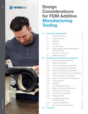
TABLE 1. Different versions of “design for additive manufacturing”grouped by focusscope of the AM processes [1]. These differences are increasingly important as AM continues to expand beyond rapid prototyping (RP) into end-use, rapid manufacturing (RM). For example, where traditional manufacturing limitations would require acomplex assembly, AM could allow for a single, pre-assembledbuild [2, 3]. Thus, there is a need for DfAM methods similar toDfM that consider the unique affordances and limitations of AMfor both RP and RM.The existing literature that refers to itself as “DfAM” can becategorized into 3 groups (see table 1). The first of these groupspropose specific design methods that utilize additive manufacturing or describe how DfAM should be part of the entire designprocess. However, not all of these provide specifics to their proposed methods, instead advocating for more research. The second group researches different approaches for overcoming limitations of AM, such as achieving very small features or reducingthe need for support structures. Specific applications now possible using AM often require a tailored process. This can have asignificant impact on the outcome of the intended design products. One such example is the ability to closely emulate naturalbiological systems, which is only now possible due to AM freedoms, but requires a different mode of thinking, even comparedto common AM methods [4]. The third group is the most closelyrelated to the purpose of our work. It focuses on general DfAMguidelines that highlight challenges unique to AM. These guidelines are usually intended to be used at any point during design.Design MethodsAM TechnologiesDfAM GuidelinesDiegel et al. [5]Adam & Zimmer [6]Adam & Zimmer [6]Doubrovski et al. [7]Dede et al. [8]Ameta et al [9]Gibson et al. [10]Garland & Fadel [11]Diegel et al. [5]Hague et al. [12]Gibson et al. [10]Meisel & Williams [13]Hague et al. [1]Gorguluarslan et al. [14]Panesar et al. [15]Laverne et al. [2]Kruth et al. [16]Pruss & Vietor [17]Madden & Deshpande [18]Maute et al. [19]Rosen [20]Morton et al. [21]Meisel & Williams [13]Rosen [22]Ponche et al. [23]Morton et al. [21]Yang & Zhao [24]Rosen [4]Panesar et al. [15]Rosen [20]Ponche et al. [23]Rosen [22]Pruss & Vietor [17]Schmelzle et al. [3]Snyder et al. [25]Stankovic et al. [26]Stankovic et al. [26]Vayre et al. [27]Ulu et al [28]Yang & Zhao [24]Vayre et al. [27]Williams et al. [29]Yim & Rosen [30]2.1Generalized DfAM ConsiderationsThe literature that defines any DfAM guidelines shows common themes (see table 2). Some of these commonalities includethe effect of part orientation [5,10,12], the inclusion of manufacturing features [10], and blunting extreme points [6]. The importance of the guidelines is that they can be used for different typesof AM processes and need to be considered in most designs.Some guidelines are important for the design process, whereasothers describe how to use the technology, such as the reorientation of a part in the respective AM machine software. Additionally, some designs can be effective, despite ignoring some guidelines. Most designs that ignore general guidelines require specialized manipulation of the AM machines or softwares by experts. Despite these caveats, the development of DfAM rules orguidelines will continue to show commonalities amongst themselves until the next novel manufacturing or prototyping processis invented and requires a new set of guidelines.While the guidelines shown in table 2 are useful and effectively convey expert knowledge, past efforts are often worded ina way that is easier for intermediate users to understand, ratherthan novices. For example, few novices will know what a support or an island is without further reading or experience. Someguidelines are more specific than most novice or intermediateusers need or understand, or would only be necessary if an AMuser creates many parts, such as putting identification markingson parts. Several, especially those by Adam and Zimmer [6],tend to be out of the control of many novices using hobby printers, such as controlling the size of the island. Additionally, fewof these appear to address common mistakes made by novices.3THE DfAM WORKSHEETThe DfAM worksheet can be found in figure 1. The sheet isdesigned for novices to additive manufacturing. It is also usefulfor intermittent or intermediate users as a checklist to go throughto validate a design prior to manufacture.3.1Process for Creating the SheetTo create the sheet, we started by reflecting on our own experiences with 3D printing and laser cutting, running 3D printinglabs, and teaching design courses where students use 3D printing.We then consulted with lab monitors at the Boilermaker Lab atPurdue to identify several common mistakes that students make.We then grouped and abstracted these principles into considerations and developed scales for these. Next, we consulted withtwo experts. The first is a machinist with decades of experiencewith AM. The second is a machine design researcher with extensive experience teaching senior design, and who is thereforefamiliar with common mistakes. We used these consultations toiterate and refine the worksheet.2Copyright 2016 by ASMEDownloaded From: http://proceedings.asmedigitalcollection.asme.org/ on 09/01/2018 Terms of Use: http://www.asme.org/about-asme/terms-of-use
TABLE 2.Guidelines described by prior papersPrincipleDescriptionPart orientationSome shapes print better in certain orientations, though sometimes there is no optimal direction [9, 10, 15]Orientation can have an effect on the surface finish of the part, especially when dealing with rounded features [5,12,13,17]The orientation can have an effect on the strength between the horizontal and vertical components (since layers are addedin the vertical ’z’ direction) [5, 9, 17]Removal of supportsRemoving support structures significantly reduces surface finish and increases the need for post-processing [10]Sharp inner edges can reduce the need for support structures as the layers build [6, 12, 17]Hollowing out partsWhen functionally possible, thick walls and hollow interiors can reduce print time [10, 24]Manufacturing featuresWhile AM does not require undercuts, draft angles, and other process specific considerations, many parts are prototypesthat will eventually be manufacturing using traditional processes [10]Interlocking featuresAM processes have a finite build space, and may require that large parts are broken up and joined later with interlockingfeatures [10]Ensure that joined/interlocking gap dimensions are minimized to enable robust removal of support structures and ensuresmall dimensional deviations [6]Reduction of part countIf the AM part is end-use, the number of parts in an assembly may be reduced [9, 10, 24]Identification marksWhen a company produces many parts, it is easy to lose track of which model is which [10]Avoid sharp edgesResults in better accuracies; rounding radii correlate with outer radii of simple-curved elements [6]Round inner edgesSimplify removal of disperse support structures (e.g. powder) [6]Blunt extreme pointsVertical points blunted parallel to build plane; horizontal points blunted orthogonal to build plane [6]Short overhangThis ensures robust manufacturability and prevents falling off of layers [6]Low Island PositionsThis will have a significant impact on the build times [6]3.2After the worksheet was near a final form, we consultedwith three high-volume 3D printing labs to see if the worksheetaddressed their common concerns. The three labs are the Purdue Boilermaker Lab, the Purdue Mechanical Engineering 3DPrinting Lab, and the Faboratory. The Boilermaker lab servesall of the Purdue campus and features several types of FDM 3Dprinters. The Mech Eng. 3D Printing Lab serves several designcourses and the department needs in general. The lab manager,who is also the first expert, has over 20 years of experience inAM and operates two SLA machines and three FDM printers.The Faboratory is a soft-robotics research laboratory and usesseveral cutting-edge AM processes on micro and macro scales.All three labs confirmed that the worksheet addresses relevantconcerns and that it was not missing any major criteria. Onemember of the Faboratory suggested that the worksheet shouldinclude some scales for intended use and material properties. Weomitted these categories since most novices will only have oneor two AM processes available to them. These considerationsare more relevant for expert practitioners who must frequentlychoose between several AM processes.Considerations for the WorksheetThe goal of the worksheet is to 1) reduce print failures, 2)improve understanding of AM limitations for novice users, and3) recommend a course of action. Some essential features of theworksheet are that it is short, very easy to use, very fast to use,and gives appropriate recommendations. We argue that an additional consideration must be that industry often will not adopta new method unless it is very easy to use or required by management. The worksheet is designed to be reminiscent of DfMworksheets. The purpose of this is to aid industry adoption. It isalso constrained to a single page to reduce complexity.The considerations we address in the worksheet are not comprehensive, but are the most prominent issues based on our qualitative observation and expert consultations. The 4 categories onthe top half of the worksheet address the most common problems we observed. These are part complexity, intended function,plans for material removal, and unsupported features. The bottom four categories address common mechanical design problems that affect the strength or integrity of the part. These areexcessively thin features, part strength, part tolerances, and theeffect of warping on geometric tolerances.3Copyright 2016 by ASMEDownloaded From: http://proceedings.asmedigitalcollection.asme.org/ on 09/01/2018 Terms of Use: http://www.asme.org/about-asme/terms-of-use
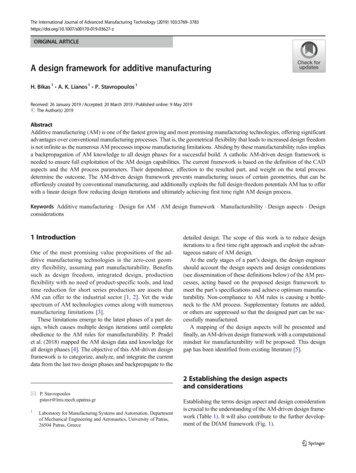
FIGURE 1.The DfAM worksheet is design for novices and intermittent users of additive manufacturing technologies.4Copyright 2016 by ASMEDownloaded From: http://proceedings.asmedigitalcollection.asme.org/ on 09/01/2018 Terms of Use: ityThe part can be made in a mill orThe part is mostly 2D and can bemade in a mill or lathe withoutrepositioning it in the clampThe part is the same shape ascommon stock materials, or iscompletely 2DSimple parts are inefficient for AMMating surfaces moveMating surfaces move somewhat,cycles.experience large*O significantly,forces, or must endure 100-1000*OMark FunctionalityOne AM parts are light and medium dutyMating surfaces are bearingsurfaces, or are expected toendure for 1000 of cyclesThere are small gaps that willInternal cavities, channels, orO require support structuresOMark Material RemovalOne Support structures ruin surface finishThe part is smaller than or thesame size as the required supportstructureThere are interior features orThin FeaturesSome walls are less than 1/16"Thin features will almost always breakInterior corners have generousWalls are more than 1/8" (3mm)O thickO chamfers, fillets, and/or ribsInterior corners have chamfers,O and 1/8" (3mm) thickO fillets, and/or ribsOMark Stress ConcentrationOne Interior corners must transition graduallyInterior corners have no chamfer,fillet, or ribSurfaces are purely non-functionalO or experience virtually no cyclesOMating surfaces will moveminimally, experience low forces,or are intended to endure 2-10cyclesWalls are between 1/16" (1.5mm)O (1.5mm) thickMarkOnecurvature is too complexO surfaceto be machinedOThe part curvature is complex(splines or arcs) for a machiningoperation such as a mill or lathe†Strongly consider a differentmanufacturing processa different manufacturing* ConsiderprocessStarred RatingsHole and length tolerances areO considered or are not importantHole or length tolerances areO adjusted for shrinkage or fitOMark TolerancesOne Mating parts should not be the same sizeHole or length dimensions arenominalThere are no internal cavities,O channels, or holesOMaterial can be easily removedfrom internal cavities, channels, orholesThere are short, unsupported33-4024-3216-238-15Needs redesignConsider redesignModerate likelihood of successHigher likelihood of successTotal ScoreThe part has small or no flator forms that need to beO surfaces,exactThe part has medium-sized, flator forms that are shouldO surfaces,be close to exactOMark Geometric ExactnessOne Large, flat areas tend to warpThe part has large, flat surfaces orhas a form that is important to beexactPart is oriented so there are noO overhanging featuresOOverhanging features have aminimum of 45deg supportO supportOverhang features have a sloppedO featuresOMark Unsupported FeaturesOne Unsupported features will droopThere are long, unsupportedfeaturesOverall Totalx1 x3 x5 x1 x2 x3 x4 x5 Sum AcrossRows TotalsA quick method for reducing the number of printing and prototyping failures, by Joran BoothInstructions: Mark one for each category for the part you plan to print. Check daggers and stars first, then scoresbut only after repositioning itmoderate forces, ordo not have openings forO lathe,O experienceO holesin the clamp at least onceare expected to last 10-100 cyclesremoving materials*O†OMarkOneDesign for Additive ManufacturingCitation: The Design for Additive Manufacturing Worksheet, by Joran W. Booth, 2015. This work is licensed under the Creative Commons AttributionNoDerivatives 4.0 International License. To view a copy of this license, visit http://creativecommons.org/licenses/by-nd/4.0/.
The most common problem we saw is that many novicesuse AM for parts that are easier to make with other methods. Forexample, we saw many novices making axles, plates, and gearsusing AM instead of using metal rods and a bandsaw or simplybuying the parts. We also observed many users expected the AMparts to endure a similar number of cycles as a machined part.Material removal and support structures is commonly ignoredby novices. For example, many novices using an SLA processcreate hollow parts but do not include holes to drain fluid fromcavities. Additionally, many novices do not consider the poorsurface quality left by support structures or the drooping seen inunsupported features.Our worksheet does not address all of the possible AM considerations. Therefore, it returns a qualitative assessment of riskof failure, rather than directly evaluating the quality of the design. Since the assessment is qualitative, it lumps manufacturing,assembly, and mechanical failures into a single score.of print jobs over the period of about a month without using theworksheet. All printers used for the study were Makerbot Replicators, each with 2000 service hours. We then kept logs of printjobs for another month after introducing the worksheet to the laband requiring all print submissions to have first completed thesheet. If students received a “redesign” recommendation fromthe sheet, they were asked to improve the part and resubmit later.The data we collected included timestamps, filenames, whetherthe print failed, whether the DfAM worksheet was used, and thescore from the worksheet. We used the filename to track if redesigned parts were resubmitted after an initial print. We shouldnote that we did not discriminate by the cause of the print failure,including common problems such as mechanical failures of theprinter or improper leveling of the build plate. This makes ourmeasure rather conservative. The scores from the DfAM worksheet were recorded in a digital version of the worksheet hostedon Qualtrics. Volunteers kept the print logs and enforced usingthe worksheet, so not all prints from the second month used theworksheet and the log is at times incomplete. Because of thisdiscrepancy, we effective have two separate datasets: the printlogs and the worksheet results from Qualtrics.We wanted to answer two questions with our analysis.3.3How to Use the WorksheetThe worksheet may be used at the conceptual stage (preferred) or at the CAD stage, but should be used prior to manufacturing a part. The eight categories are listed in columns, and ascale is found below each category title. A user marks how theirdesign fares on the scales in each category. When all the marksare complete, the user sums the total for each row and multipliesthe sum to get a total for each row. The totals are then summedto calculate an overall score.The user then examines the two scoring schemes at the bottom of the worksheet. The first scoring scheme is a go-no-goassessment based on the first two categories only. If the no-gocondition is flagged, the user is instructed to search for a simplermanufacturing method. If the design survives the first scoringscheme, the second scoring scheme suggests a likelihood of thepart being of good quality. If the score is high, the user shouldconsider redesign. If it is low, they can expect a higher likelihood of success. After the first time using the sheet, the user canglance at the images on the sheet to remind them of the scalelevels rather than reading each question. How long does using the worksheet take? Does the DfAM worksheet reduce the number of design iterations as measured by the quantity of printer errors and partrevisions (i.e. reprints)?According the survey log from Qualtrics, the number ofsamples was 102, the median time spent on the worksheet was2.7 minutes, and the average was 5.4. Three observations wereremoved due to being longer than four hours because it is almostcertain that in these cases the browser was left open.To analyze the second question, we split the print log datacollected at the Boilermaker Lab into two groups: prints whichdid not use the worksheet and prints which did. We then countedthe number of failures in each group and divided these by the total prints in each group to get a failure rate. We also used the filename to determine how many prints were repeated. The reprintrate is how many parts are reprinted divided by the total. Summary statistics can be found in table 3.The group which did not use DfAM is much larger than thegroup which did for two reasons. First, the initial month whenwe collected data was at the end of the semester when more student projects are being printed, and the month after implementingthe DfAM worksheet was in the first month of the new semesterwith fewer student projects. Second, the worksheet was not consistently applied to the month with the DfAM sheet, and so manyof the prints over this period were included in the first group. Thesensitivity analysis we present later in this paper uses data fromthis second month, only.The overall changes we observed were quite dramatic. Theoverall number of failures dropped 42% after implementing the4EVALUATION OF THE WORKSHEETTo evaluate the effectiveness of the worksheet, we wanted toknow if the design cycle was positively affected by the worksheetby reducing the number of iterations a designer must take to create a viable part. Since it would be difficult to track hundreds ofdesigners, and since a laboratory study would necessarily restrictthe sample size, we opted for simple metrics to test its effectiveness. The number of iterations for designing a part can beapproximated by measuring the number of failed 3D prints andhow many files are reprints.We collaborated with the Boilermaker Lab, a high-volume3D printing facility which serves the entire Purdue Universitycampus, to measure the effect of the worksheet. We kept logs5Copyright 2016 by ASMEDownloaded From: http://proceedings.asmedigitalcollection.asme.org/ on 09/01/2018 Terms of Use: http://www.asme.org/about-asme/terms-of-use
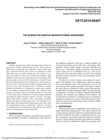
TABLE 4.Examples of prints created after using the DfAM worksheetScore 24Score 22Score 19Score 16Score 15Score 11TABLE 3. Change in the print failure and reprint rate due to introducing the DfAM worksheet, including a reduced set of dataw/o DfAMw/ DfAMmonth 1 & 2month 2n19236Print fail rate19.8%8.3%42% decreaseRepeat print rate14.1%5.6%39% decreasew/o DfAM,w/ DfAMChangemonth 2 onlymonth 2n4736Print fail rate10.6%8.3%78% decreaseRepeat print rate6.4%5.6%87% decreasewith more samples. It is important to note that the drop in failurerate is a conservative estimate because we included ALL sourcesof failure, not just those due to poor part design. The repeat printrate also gives us a better idea of the positive effect this worksheethas on the design cycle.ChangeWe conducted a sensitivity analysis with this data as well. Itis possible that the data collected before implementing the worksheet had more errors due to it being collected at the end of thesemester when students are frantic to complete projects. To testfor this, we removed the data from the prior semester and onlycompared prints with and without the DfAM worksheet duringthe same time period. We found that the overall print rate was78% lower when users used the DfAM worksheet, confirmingthe magnitude of the prior result. We also found that there werea similar number of repeated prints for both conditions over thesame period, which suggests that the drop in print rate may notbe accurate. However, this highlights the need for further datacollection. This alternate test increases confidence that our worksheet is effective for novice and intermediate users of AM.We also qualitatively compared existing part designs to theratings the sheet yielded for those parts. We found that the ratingsof the sheet are consistent, even at the boundaries between tworating levels. Several examples can be found in table 4.DfAM worksheet and the rate at which prints needed to be redonedecreased 39%. Additionally, there were no third reprints doneafter the worksheet was implemented, though this may change6Copyright 2016 by ASMEDownloaded From: http://proceedings.asmedigitalcollection.asme.org/ on 09/01/2018 Terms of Use: http://www.asme.org/about-asme/terms-of-use
5CONCLUSIONS AND RECOMMENDATIONSIn this paper, we present a design for additive manufacturing (DfAM) worksheet designed for improving part quality fornovice and intermittent users of additive manufacturing (AM)technologies. The worksheet is unique from prior efforts becauseit accounts for users with low experience and is constructed in away that simultaneously advises on the quality of the part andsuggests improvements that can be made to it. When we implemented the worksheet in a high-volume 3D printing lab, we sawat least a 42% decrease in the print failure rate and a 39% decrease in the reprint rate. These results demonstrate the sheet canhelp reduce the design cycle for novice and intermediate users.Based on these results, we recommend using this worksheetin academic and industry environments. Some limitations to thiswork include sampling from a single university and a potentialfor inconsistent print logs due to low motivation on the part oflab monitors. While this may limit the potential accuracy ofour results, our sensitivity analysis confirms the direction and thesignificance of the change. Based on these results, future workshould focus on computer-based recommender systems embedded in CAD. Many of the principles in this worksheet can bemeasured in a CAD environment once an orientation is selected,including wall thickness, the degree to which features are unsupported, and the degree of complexity.[3] Schmelzle, J., Kline, E. V., Dickman, C. J., Reutzel, E. W.,Jones, G., and Simpson, T. W., 2015. “(re) designing forpart consolidation: Understanding the challenges of metaladditive manufacturing”. Journal of Mechanical Design,137(11), p. 111404.[4] Rosen, D. W., 2007. “Design for additive manufacturing: Amethod to explore unexplored regions of the design space”.In Proceedings of the 18th Annual Solid Freeform Fabrication Symposium.[5] Diegel, O., Singamneni, S., and Withell, S. R. . A., 2010.“Tools for sustainable and product design and additivemanufacturing”. Journal of Sustainable Development, 3,pp. 68–75.[6] Adam, G. A., and Zimmer, D., 2014. “Design for additivemanufacturing: Element transitions and aggregated structures”. CIRP Journal of Manufacturing Science and Technology, 7(1), Jan., pp. 20–28.[7] Doubrovski, Z., Verlinden, J. C., and Geraedts, J. M. P.,2011. “Optimal design for additive manufacturing: Opportunties and challenges”. In Proceedings of the ASMEIDETC/CIE.[8] Dede, E. M., Joshi, S. N., and Zhou, F., 2015. “Topologyoptimization, additive layer manufacturing, and experimental testing of an air-cooled heat sink”. Journal of Mechanical Design, 137(11), p. 111403.[9] Ameta, G., Lipman, R., Moylan, S., and Witherell, P., 2015.“Investigating the role of geometric dimensioning and tolerancing in additive manufacturing”. Journal of MechanicalDesign, 137(11), p. 111401.[10] Gibson, I., Rosen, D. W., and Stucker, B., 2010. AdditiveManufacturing Technologies: Rapid Prototying to DirectDigital Manufacturing. Springer, New York.[11] Garland, A., and Fadel, G. M., 2015. “Design and manufacturing functionally gradient material objects with an offthe shelf three-dimensional printer”. Journal of MechanicalDesign, Transactions of the ASME, 137(11).[12] Hague, R., Campbell, I., and Dickens, P., 2003. “Implications on design of rapid manufacturing”. Journal of Mechanical Engineering Science, 217 Part C., pp. 25–30.[13] Meisel, N., and Williams, C., 2015. “An investigation ofkey design for additive manufacturing constraints in multimaterial three-dimensional printing”. Journal of Mechanical Design, 137(11), p. 111406.[14] Gorguluarslan, R. M., Park, S.-I., Rosen, D. W., and Choi,S.-K., 2015. “A multilevel upscaling method for material characterization of additively manufactured part underuncertainties”. Journal of Mechanical Design, 137(11),p. 111408.[15] Panesar, A., Brackett, D., Ashcroft, I., Wildman, R., andHague, R., 2015. “Design framework for multifunctionaladditive manufacturing: placement and routing of threedimensional printed circuit volumes”. Journal of Mechani-ACKNOWLEDGMENTWe thank the reviewers for their valuable feedback. Thiswork was supported by the Lambert Fellowship through the Mechanical Engineering department at Purdue Universi
a background on Design for Additive Manufacturing (DfAM) principles, the worksheet, and validation of the worksheet. We recommend this worksheet for companies that are considering or learning new AM processes, such as 3D printing. We also recom-mend it for design and manufacturing cours