Transcription
Specialists in fireplace design and manufactureSUPER NOVA INSERT RFINSTALLATION & OPERATING INSTRUCTIONSIMPORTANT:INSTALLER, PLEASE LEAVE THESE INSTRUCTIONS WITH THE UNIT ON COMPLETION.10 YEAR FIREBOX WARRANTYThe firebox is covered by a 10 year warranty.Other parts are covered by a one year limited warranty.Head Office – 13 French Avenue, Brendale, Queensland 4500Telephone – PH: (07) 3490 5500Facsimile – FAX: (07) 3490 5520Website: - www.jetmaster.com.auBusiness hours: - Monday to Thursday 7:30am-4:00pm. Friday 7:30am-2:00pmEmail: - sales@jetmaster.com.au
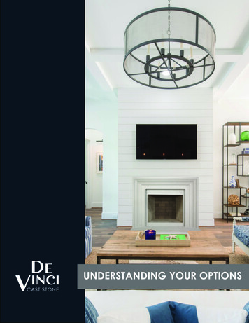
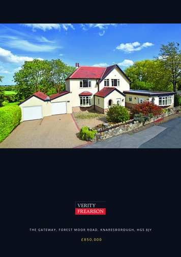
DIMENSIONSSUPER NOVA INSERT RF – STANDARD FASCIA/CAST IRON FASCIA507480GE*IFascia omittedBD*F251H450ACAMEASUREMENT 800B1000C650D*E*STDC / IRONSTDC / IRON434470330377FGHI660661320820Denotes measurement from standard and cast iron fascia, measurement is also dependent on fasciaposition placement.20/07/2022Ver.222
TECHNICAL SPECIFICATIONSPERFORMANCE:Average peak heat output – 11.6 kWAverage Fuel consumption - 1.9 kg/hr.Average efficiency – 66%Weight – 128 kg.*Average dry fuel (hardwood) consumption rate in kilogram/hour when heater is used normally andsafely.FIREBOX IS DESIGNED TO BE INSTALLED IN A MASONRY (BRICKWORK ORHEBEL BLOCK) CAVITYCAUTION – The gap between the top of the unit and the brick work should be no more than25mm. This will prevent the fascia being exposed to radiant heat from the flue. Any gap larger than25mm, should be shielded with non-combustible material (Masonry, Metal and/or insulating material.)Fans must be installed & operational at all times when a timber mantle is installed.Minimum Hearth Requirements – Thickness to be a minimum of 9mm non combustible material andmust extend 300mm in front of firebox door and 300mm to each side of the firebox door.NOTICE TO ALL INSTALLERS:DURING THE INSTALLATION OF THE FAN, MAKE SURE TO PULLTHE FAN CORD OUT UNTIL THE CABLE TIE STOPS ON THE INSIDEOF THE CONDUIT. DO NOT AT ANY CIRCUMSTANCE PUSH THECORD BACK THROUGH INTO THE BOX.20/07/2022Ver.223
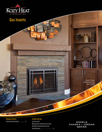
BAFFLE PLATE INSTALLATION1. MAKE SURE TO INSTALL AIR TUBE ASREQUIRED. THE OPENING ON THE TUBEEND NEEDS TO BE AGAINST THE BACKWALL. ALL ROUND EXIT HOLES MUST BEPOINTING TO THE BOTTOM OF THE FIREBOX OR THE SIDE WALLS.2. CERAMIC BAFFLE PLATES SIZE230mmX240mm. INSTALL THE BAFFLEPLATE 230mm FRONT TO BACK, 240mmSIDE TO SIDE. GET BAFFLE PLATEINSIDE THE FIREBOX AND TILT ON ANANGLE. PUSH BAFFLE PLATE OVERTHE AIR TUBE3. THEN MOVE SIDEWAYS UNTIL SUPPORTEDBY THE SUPPORT PLATE AND TOUCHING THESIDE WALL. MAKE SURE THE BAFFLE PLATEALSO TOUCHES THE REAR WALL.4. REPEAT THE PROCESS FOR THEOTHER SIDE.20/07/2022Ver.224
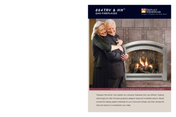
INSTALLATION INSTRUCTIONSUPER NOVA MASONRY/TIMBER CAVITYINSTALLATIONplaincrimpedFlue system to be installedto suit AS/NZS 2918.2001All 8”-10” assembled flues musthave the crimps pointing upwardsTriple skin flue system(10”, 8” and 6”)DETAIL A25mm min. clearance between10” flue and framingcrimpedCeilingplain9 mm Fibre cementsheetAAll 6” assembled flues must havethe crimps pointing downwardsStainless steel flue pipe.All flue pipes must beconnected with pop rivetssupplied by installer6” FlueDETAIL BRear timber stud wall(combustible wall)Register plate with vented upstandsMinimum 600mm below ceiling.25mm air gapInsul wool (supplied by installer) canbe placed on top of register plateB1 row of Hebel or brick to be used aboveregister plate before timber frame work is used1000*Outlet air vents from chase*1000mm of masonrymaterialHebel Block –min. thickness – 75mm165925mm min. air gap650Rear of unit toHebel Block – 30mm min.9Inlet air vents into chase20/07/2022Ver.225
INSTALLATION INSTRUCTIONSUPER NOVA MASONRY/TIMBER CAVITYINSTALLATION25mm min. clearance between10” flue and ceiling/framingFlue system to be installedto suit AS/NZS 2918.2001Triple skin flue system(10”, 8” and 6”)9mm Fibre cementsheet600mm min.Below ceilingRegister plate withvented 8” and 10” upstands600mm min. below ceiling1 row of bricks over register plateOutlet air vent 240 x 906” FlueNOTE:1.2.25mm air gap3.Minimum 50mm air gap betweenunit and masonry for air circulationTop and bottom vents are requiredfor convection of cavity air300mm clearance min. between unitand combustible frame workInlet air vent 240 x 90757530020/07/2022300Ver.226
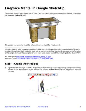
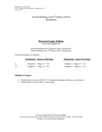
MANTLE DIMENSIONS250mm260mm350mmFore hearth is 9mmThick and consistedof Bellis board300mm765 minimumMantle 350mmabove hot airoutlet deflectorMantle upright to beno closer than150mm from the fuelloading door openingand extend into theroom by no more than100mm.Hearth is 9mm thick and consisted of Bellisboard or similar product and must extend aminimum of 300mm forward of the fireplaceand either side of the fuel loading dooropening.20/07/2022Ver.227
INSTALLATION INSTRUCTIONSUPER NOVA FULL MASONRY CHIMNEYINSTALLATIONImproved heating efficiency is achieved by admitting cool air into the brick cavity where it is heated by theouter skin of the firebox and active flues, then released back into the room via hot air outlet vents.NOTE: - Top of brick chimney can be left open, where no trees can cause a build up of leaves etc. on topthe weather plate. Weep holes must be left at weather tray level as no smoke outlet holes will be needed insides of chimney.S/steel CowlS/steel weather trayWith upstandRun a bead of silicone downthe vertical seam of the outercasing to the weather tray.S/steel weather traywith upstand and 20mmdown turnTop vent 240 x 90Directly belowregister plateRegister plate withvented upstandsMinimum 600mmbelow ceiling.6” FlueBottom vent 240 x 90930066150mm min.Between and brick20/07/2022Ver.2250mm min.Between and brick8
INSTALLATION INSTRUCTIONSUPER NOVA FULL MASONRY CHIMNEYINSTALLATIONALTERNATIVE BRICK CHIMNEY TERMINATION:2- off 350mm x 172mm chimneyopening minimum sizeNOTE: If chimney is more than 950mm widethen the two outlets only are quite practicalon the long side of chimney – width of outletto be widened in accordance with the lengthof the chimney.2- off 230mm x 172mm chimneyopening minimum sizeFibre cement ‘collar’ around flueBrick capping( 20mm overhang )Fibre cement sheets of sufficientthickness to support brick cappingand splayed render and to providea collar to restrain top of flue6” stainless steel active flue20/07/2022Ver.229
20/07/2022Ver.2210
20/07/2022Ver.2211
20/07/2022Ver.2212
20/07/2022Ver.2213
INSTALLATION INSTRUCTIONSMINIMUM HEIGHT OF FLUE SYSTEM EXITINSTALLATION TO COMPLY WITH AS/NZS 2918ANY NEARBYSTRUCTURE6000MORE THAN 30003000OR LESS600 MIN1000 MIN IF CLEAR WITHIN3000 OF TOP OF FLUEINCREASE AS NECESSARY UNTILNOTHING WITHIN 6000 OF THE FLUETOP3000 OR LESS3000MORE THAN 30003000600 MININCREASE FROM 1000 MINUNTIL CLEAR WITHIN 3000 OFTOP OF FLUEDIMENSIONS IN MILLIMETRES20/07/2022Ver.2214
WARRANTY1.Kemlan wood heaters carry a warranty on the 6mm firebox for a period of ten (10) years.2.This warranty also covers other components of the heater for a period of one (1) year. These components include thebaffle plate, handle assembly, secondary air tubes and fan.3.Kemlan’s warranty covers the wood heaters against defects in materials and manufacture.4. THIS WARRANTY DOES NOT COVER –4.1 Failure to comply with manufacturer’s operation instructions.4.2 Normal wear and tear or damage caused by incorrect installation.4.3 Any form of rust and/or corrosion to the painted finish of the heater.4.4 Damage to the glass in the door, if the damage is caused by impact or misuse.4.5 The cost of collection and delivery of the wood heater and/or parts.4.6 Damage caused by water ingress.4.7 Cost of removal of defective heater or re-installation of replacement heater.4.8 Failure to use fireplace components supplied by Kemlan Industries Pty Ltd.4.9 Cost of inspection for damaged heater.5.CLAIMS –5.1 (I) Kemlan will provide a full replacement of the heater in the first five years after installation.(ii) Replacement in the subsequent five years (i.e. sixth to tenth year after installation will be on the following basis.Owner will pay fifty percent of the current retail price, if the claim is made in the sixth year – tenth year afterpurchase.5.2Replacement of heater subject to all conditions in section four of warranty.5.3Should any defects occur, contact the Kemlan distributor from whom you purchased the heater.5.4Under this warranty the defective parts will be repaired or replaced, free of charge.6.The fireplace installation must comply with the relevant local statutes, ordinances, regulations and by-laws.7. THIS WARRANTY IS VOID IF:7.1 The appliance has been over-fired or operated in atmospheres contaminated by chlorine, fluorine or otherdamaging chemicals. Over-firing can be identified by, but not limited to, warped plated or tubes, rustcoloured cast iron, bubbling, cracking and discolouration of steel or enamel finishes.PLEASE COMPLETE AND RETAIN THIS SECTION FOR YOUR RECORDSPurchased from: .Address: .Date of Purchase: .20/07/2022Ver.2215
4.3 Any form of rust and/or corrosion to the painted finish of the heater. 4.4 Damage to the glass in the door, if the damage is caused by impact or misuse. 4.5 The cost of collection and delivery of the wood heater and/or parts. 4.6 Damage caused by water ingress. 4.7 Cost of removal of defective heater or re-installation of replacement heater.