Transcription
07WTM003045 53251-01 rE.qxd3/2/072:30 PMPage 1Layout GuideEasy, step-by-step,underground sprinklersystem layout guideFREE SPRINKLERSYSTEM DESIGNSee page 5 for details
07WTM003045 53251-01 rE.qxd3/2/072:30 PMPage 2Planning & DesignFlowWaterMeter3/4” Water ServiceLine for HouseMain SprinklerShut-OffCompressionTeeSpring-Loaded Pop-Upwith Adjustable NozzlePre-AssembledSwing-Joint1WHY INSTALL AN UNDERGROUND IRRIGATION SYSTEM? Conserve Water & Money – Reduce over-watering and water when evaporationlevels are low. Save Time – Enjoy a beautiful yard and spend more time doing the things you like. Increase Property Value – Greener, thicker lawns, shrubs and trees, make your propertymore attractive. Eliminate Yard Clutter – Eliminate the ugly tangle and yellow marks left by unsightlygarden hose.CHECK LOCAL CODES2Water DistrictCall your local water district for requirements concerning permits, plumbers, backflow preventionand pipe requirements.2Sprinkler System Layout & Installation Guide
07WTM003045 53251-01 rE.qxd3/2/072:30 PMPage 3Planning & DesignSprinklerTimerSprinklerWireMain SprinklerLine 1"Anti-SiphonDeviceValveManifoldLateral SprinklerLine 3/4"HeaderLine 1"Common Questions To Ask Your Water District: Is a permit required? Yes No Is a licensed plumber required for connecting to the main water supply? Yes No What type of backflow prevention device is required? Double Check Pressure Vacuum Breaker Automatic Anti-siphon Valve Dual Check Valve Climate: Will pipes freeze in my area? Freezing Non Freezing How deep should I bury my pipes?Pipe Depth What type of pipe is required (or recommended) for my area?Pipe type:Utility CompaniesBefore digging, contact your local gas, power, telephone, and cable companies to markunderground cables and pipelines on your property, such as: Gas Power Other Phone TV & Internet cablesSprinkler System Layout & Installation Guide3
07WTM003045 53251-01 rE.qxd3/2/072:30 PMPage 4Planning & Design3MEASURE WATER FLOWYou need to determine the available water flow for your sprinkler system so you'll knowhow many sprinkler heads can run at one time. Water flow is measured in gallons per minuteor GPM.Measure Your Water Pressure Attach an Orbit pressure gauge (part #53020, 91130) to an unregulated outsidefaucet*. Unregulated means a line withouta pressure regulator.180160140200020Orbit120psi100 80 Open the faucet and record the readingon the gauge. No water should be runningduring the sure the Main Water Service Line Wrap a piece of string around your mainwater service line then measure the lengthof the string. Use the table to convert the string lengthto pipe size (diameter).Note: The main water service line is the pipe that runs fromthe water meter to the house. If you're connecting to a lineother than the main line, measure the line that you will beconnecting to.DETERMINE SIZE OF SERVICE LINELength of string2"2-3/4"Copper pipe size1/2"3/4"PVC or galvanized pipe size1/2"3-1/4"3-1/2"4-1/4"1"3/4"Pipe Size1"System CapacityWATER PRESSURE (PSI)MAINLINESIZE35 LB. 40 LB. 45 LB. 50 LB. 55 LB. 60 LB. 65 LB. 70 LB. 75 5 15.07.07.58.09.013.0 14.015.016.0 17.516.018.520.017.59.5Use the mainline pipe sizeand pressure(PSI) taken todetermine thegallons perminute (GPM)capacity of yoursystem.21.0GPM Capacity* If an unregulated faucet is unavailable, call the local water district for an estimated PSI.Important: If your water pressure exceeds 80 PSI, use a pressure reducer. Excessive pressure may damage system.4Sprinkler System Layout & Installation Guide
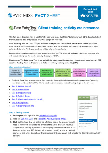
07WTM003045 53251-01 rE.qxd3/2/072:30 PMPage 5Planning & Design4MEASURE & DRAW PROPERTYMeasure your property and create a top down view on graph paper (supplied in this guide).Make the drawing to scale. For example, each one-inch square represents 10 feet on the graphpaper, or each small square 1 foot.40'Draw Propertyto uildings, sidewalks, patios,driveways and treesLabel:Grass, flower beds andwater meterlocationTREE10'10'40'73'LET ORBIT DESIGN YOUR SPRINKLER SYSTEMSTOPTIME SAVINGTIP!Instead of continuing on to the next section,go to www.orbitonline.com and use the freesprinkler system design program.What you receive: Detailed color-coded drawings with: Sprinkler placement and spray patterns Layouts of individual sprinkler zones/stations Valve and sprinkler pipe placement. Step by step assembly instructions. Detailed parts list for PVC or Poly-Pipe systems. Quick turn around – Completed in about 2 days.SELECT HEADS5Select sprinkler heads you would like to use for each area and make a note of each type onyour drawing.Select Head Type for Each SectionSprinklers are generally divided into three categories: Large Area SprinklersAreas larger than 25' x 25' Medium Area SprinklersAreas smaller than 25' x 25' Small Area SprinklersAreas with flowers, shrubs, and ground coverNote: Refer to page 22 (Selecting Your Products) to determine the best sprinkler for your yard.Sprinkler System Layout & Installation Guide5
07WTM003045 53251-01 rE.qxd3/2/072:30 PMPage 6Planning & DesignSmallSelect Heads ForEach AreaTREELargeVoyager II PATIOMediumSpring-LoadedPop-UpSmallOur example uses: Voyager II in the back yard Spring-Loaded Pop-Up (withadjustable nozzle) in the frontand side yard Mushroom bubblers in thefront flower areasDRIVEWAYTREEMediumSpring-Loaded Pop-UpLarge Area HeadsFor large open areas such as backyards and play areas. Space heads 15' to 45' apart(depending on sprinkler type). Gear Drive – Voyager II and Saturn III - Easy to adjust- Produces a smooth quiet rotating spray- Closed case design resists clogging from grit, sand and heavy grasses Impact (Satellite and 1 2" Brass Impact)- Simple and reliable flow-through design that utilizes an efficient impact mechanismVoyager II – Spaced 20' to 40'Saturn III – Spaced 15' to 30'Satellite – Spaced 25' to 45'Medium Area HeadsCommonly used in front and side yards. Spring-Loaded Pop-Up with adjustable pattern- Easy to adjust pattern 25 - 360 Medium Area HeadsPop-up heads & Flush headsSpacing: 10 to 15 feet Spring-Loaded Pop-Up with fixed pattern- Available in Full, 1/2, 1/4 and strip pattern nozzleSmall Area HeadsCommonly used for flooding flower beds and ground coveror to spot water trees and shrubs. Mushroom Bubbler II - Adjustable flowNote: Orbit DripMaster is a water saving alternative to small area heads. Go towww.orbitonline.com for more information.Small Area HeadsStream & Bubbler headsSpacing: 3 to 5 feet6Sprinkler System Layout & Installation Guide
07WTM003045 53251-01 rE.qxd3/2/072:30 PMPage 7Planning & Design6PLAN HEAD PLACEMENTHead to Head CoverageProper sprinkler placement allows even watering andreduces dry patches.Proper placement requires: Head to head coverage: Each sprinkler should sprayto the head beside and across it. Equal spacing between heads: Permits uniform waterdistribution.Placement Example: Good Good Overlap Head to head coveragePlacement Example: BadThere is not enough overlap. The center is notgetting water. Not enough overlap No coverage in centerSidewalkNarrow StripsOn narrow strips of grass use strip patternspray heads and space them evenly apart.These heads may be used for narrowstrips up to 4 feet wide.Evenly space strip heads on narrow sections.Place Heads in Corners Begin by placing a sprinkler ineach corner on your drawing. Use a compass to draw thespray pattern.Note: Use chart 2 on page 20 to obtain spraydistance.Sprinkler System Layout & Installation Guide7
07WTM003045 53251-01 rE.qxd3/2/072:30 PMPage 8Planning & DesignAdd Heads andAdjust Spacing Add sprinklers alongthe sides or center toincrease coverage.7CREATING WATERING ZONES OR STATIONSA watering zone or station consists of a group of sprinklers attached to one valve.The number of heads per zone will be determined in this section.Purpose of ZonesZones are designed to: Maintain adequate water flow for optimal spray coverage (Avoid dry patches) Separate areas based on watering requirements- Shade vs. Full Sun Areas- Lawn vs. ShrubsImportant: Do not mix sprinkler types in the same zone (e.g. Gear Drive, Impacts, Pop-Ups and Bubblers) Do not exceed the maximum sprinkler heads recommended per zone Use the recommended pipe size in this guide. Smaller diameter pipe will decrease the water flow.Group Heads of Same Type in the Same AreaStarting with large area heads, use the followingexample as a guide. Identify all large area heads onyour drawing.Divide Large Area Heads into ZonesSTEP 1: Maximum Heads Per ZoneLargeUse the following information (collected earlier) todetermine zone capacity: Main Line Size Water Pressure (PSI) Large area head selectedUse Orbit’s Quick Reference (Chart 1, Page 20)to determine the maximum heads per zone for yoursprinkler system.Large area heads circled8Sprinkler System Layout & Installation Guide
07WTM003045 53251-01 rE.qxd3/2/072:30 PMPage 9Planning & DesignQUICK REFERENCE – MAXIMUM HEADS PER ZONE ESTIMATESMAINLINESIZESCH.40PVCWATER PRESSURE (PSI)Gear Drive30 PSI40 PSI50 PSI60 PSIVoyager II 1223Saturn III 2234Example – We have determined that our homehas a “Main Line” size of 3/4” witha “Static Water Pressure” of 60 psi. Based onthis information, and using the QuickReference, we see that we cannot usemore than three Voyager II sprinklers inthe same zone.STEP 2: Identifying Sprinklers in a ZoneBegin grouping large area heads, ensure you do not exceed your “Maximum Heads per zone number.”Example – Since we determined (in our example above) that 3 Voyager II headsis the maximum zone capacity, we grouped all large area heads into 2 zones.Step 3: Medium and Small Area Head ZonesRepeat steps 1 & 2 to determine and identify zones for Medium Areas Heads. Repeat again forSmall Area Heads.Step 4: Number Each Zone Assign a number to each zone.Sprinkler System Layout & Installation Guide9
07WTM003045 53251-01 rE.qxd3/2/072:30 PMPage 10Planning & Design8PLAN VALVE PLACEMENTYou'll need to select a location for your main shut-off valve and the best location for thesprinkler valve manifold.Main Shut-Off ValveThe Main Sprinkler Shut-Off valve is the valve that shuts off water to the entire sprinklersystem. Connection to the main water supply is “downstream” of your water meter. Markthe location on your plan.FRONTVALVEMANIFOLDWATERMETERMAIN LINE TOREAR MANIFOLDMAIN LINEMAIN SPRINKLERSHUT-OFF VALVETO HOUSEWATER METERValve Manifold LocationOne valve will be used for each zone. Valves that are grouped together are called a manifold.It’s common to install one manifold in the front yard and one in back.Mark the Location on Your PlanTip: The valve manifold(s) should be installed in an accessible location, away from heavy foot traffic, where it is easy to operateand service. It's also a good idea to locate the manifold on elevated ground, to avoid water accumulating around the valves.Plan Backflow PreventionA backflow prevention device is used to stop foreign material from siphoning back into themain water supply. The local code information you gathered from your water district shouldinclude the type of device to install and where and how it should be installed. Plan a locationfor your backflow prevention device and draw it on your layout.Three common typesDouble CheckPressure Vacuum BreakerAutomatic Anti-Siphon ValveNote: For certain Canadian areas Dual Check Valves are used10Sprinkler System Layout & Installation Guide
07WTM003045 53251-01 rE.qxd3/2/072:30 PMPage 11Planning & Design9DIAGRAM PIPE LAYOUTYou need to plan and draw the layout for your main sprinkler line and lines for each zone.Main Sprinkler LineDraw the MainSprinkler LineRouteUse a direct routeto draw the mainsprinkler line fromthe main shut-offvalve to the frontand back yardmanifolds.Important: Your mainsprinkler line should be1 size larger than thewater main supply line.Header and Lateral Lines GuidelinesHeader lines – Attaches to a valve and supplies water to the lateral lines Do not use pipe smaller than 1" Do not attach sprinklers to this lineLateral lines – Pipe that branches off from the header line and supply water to the sprinkler heads Do not use pipe smaller than 3/4"Good Layout ExampleThis is a good layout because the water is evenly distributedbetween the lateral lines and individual sprinklers.LateralHeaderBad Layout ExampleThis is a bad layout because there is no header line. Thesprinkler heads, located at the end of the line, will have lesswater pressure than the heads located closer to the valve.Sprinkler System Layout & Installation Guide11
07WTM003045 53251-01 rE.qxd3/2/072:30 PMPage 12Planning & DesignHeader LineDraw a header line from the manifold to each zone. Header lines willbe intersected with lateral lines.Sprinkler heads should not beinstalled on this line.Use 1" PipeLateral LinesDraw lateral lines that connect theheader line to sprinkler heads.These lines should be branching,not circular.Use 3/4" pipe10PLAN TIMER LOCATIONSelect a location near a power source and where it's easy to access. You'll need to be able torun sprinkler wire to each valve. If you select a location outside, the timer should be made foroutdoor mounting or protected with a weather resistant box.Timer Placement & SprinklerWire RouteSPRINKLER WIRE Mark the planned location for thesprinkler timer Draw the route the sprinkler wirewill use to connect the timer to thefront and rear manifoldsTIMER12Sprinkler System Layout & Installation Guide
07WTM003045 53251-01 rE.qxd3/2/072:30 PMPage G1Planning & DesignSystem LayoutGraph PaperHelpful ToolsPlanning50' or 100' Tape MeasurePencilOrbit Pressure GaugeSprinkler System Layout & Installation GuideCompassRulerStringG1
07WTM003045 53251-01 rE.qxd1003/2/072:30 PMPage G2Layout Graph Paper90807060504030201001020304050607 0
07WTM003045 53251-01 rE.qxd3/2/078090Page G3 1” or 10’ 1/10” or 1’Graph Scale7 02:30 PM100110120130140
07WTM003045 53251-01 rE.qxd3/2/072:30 PMPage G4Planning & DesignInstalling YourSprinkler SystemHelpful ToolsInstallationGround PaintShovelScrew DriverPipe WrenchWire Cutter/StriperG4Orbit Sprinkler FlagsOrbit Pipe Cutting ToolAdjustable PliersHacksawThread Seal TapeSprinkler System Layout & Installation Guide
07WTM003045 53251-01 rE.qxd3/2/072:30 PMPage 13Installation1INSTALLATIONThis section will show you how to install your sprinkler system.2SYSTEM LAYOUTMarking Head andPipe LocationBegin by markingthe entire layout Use Orbit sprinkler flags to markeach head.Painted Lines Use ground paint tomark where sprinkler pipes will run.Important: Refer to your local code information for any regulations about connecting to the water main. Before digging, contact utility companies and have them mark utility lines. Obtain permits (if required). Always use gloves and safety goggles when installing.3CONNECT TO WATER MAINDig Access HoleWater Meter and Main Shut-Off1. Dig to expose thewater service line(downstream fromthe meter).2. Shut off the mainwater supply(located next tothe meter).Flow3. Open a faucet torelieve pressurein the pipes.Connect Here forMain Sprinkler LineWater ServiceLine for HouseSprinkler System Layout & Installation Guide13
07WTM003045 53251-01 rE.qxd3/2/072:30 PMPage 14InstallationConnect to Main LineInstall a Slip Compression TeeShut–Off Valve Clean off the water service pipe(downstream from meter).Water Meter Cut out a section of pipe – half thelength of the tee.Slip Joint TeeTo House Install nuts and washers on eachside of the pipe.Water Service Line Insert the slip joint tee and tightenthe nuts with a wrench.Shut-Off Valve – Non-Freezing AreaMain Sprinkler LineInstall a Gate or Ball valve after the tee andcover it with an Orbit valve box to protect itand for easy access to the valve.SystemShut–OffValveShut–Off ValvePipeNippleWater Meter Use fittings to install a Gate or Ball valveon the tee. Turn on water to flush line of debris. Cover with an Orbit valve box.Slip Joint TeeWater Service LineImportant: Frost Areas or Basement Located Water MetersDo not use the example above if you are connecting to a water supply linethat is located in an area with freezing temperatures or a line that has a watermeter located in the basement.For help in making the proper connections go to www.orbitonline.com fordetailed recommendations or contact your home improvement center.BACKFLOW PREVENTION4Install a back-flow prevention device (if required). Use local code information to determine: What type of device is required How it needs to be installed Who is authorized to install it14Sprinkler System Layout & Installation Guide
07WTM003045 53251-01 rE.qxd3/2/072:30 PMPage 15Installation5DIG TRENCHESUsing the painted lines as your guide (see System Layout, Page 13) dig trenches to the depthrequired by local codes.Important: Refer to your local codes to determine how deep your header and lateral lines need to be. Always contact your localutility companies before digging.Methods for Digging Trenches By Hand – Ideal for soft soils and very small jobs With Trenching Machine – Available at equipment rental dealersUnder Driveways andSidewalksSidewalkUse an Orbit Walkway Tunnel Kit(part # 53333, 91129) to tunnelunder obstacles. Dig a trench on both sides. Attach a garden hose to thetunneling pipe.ExpansionJointBirds eye viewSidewalk Turn on the garden hosefaucet. Work the pipe back and forth,allowing the water spray toform a tunnel.6WORKING WITH PIPEDecide whether you'll use PVC or Polyethylene pipe for your system. Both types are easy touse, but they are assembled differently. Read about each type below to make your selection.Working with PVC Pipe Using an Orbit cutting tool, cut pipe to length and cleanthe end. Apply PVC primer and PVC cement, using instructionsprovided. Insert pipe into fitting.Working with Polyethylene Pipe Using an Orbit cutting tool, cut poly-pipe to length. Slide a stainless steel clamp over the end of the pipe. Insert a barbed fitting into the pipe. Tighten the clamp over the pipe and fitting.Warning: Poly pipe should not be used for the main line to the manifold.Sprinkler System Layout & Installation Guide15
07WTM003045 53251-01 rE.qxd3/2/072:30 PMPage 16Installation7INSTALL MAIN LINEUse PVC schedule 40 (or other pressure-rated pipe) to connect the main shut-off valve tothe valve manifold(s).Important: Use pipe one size larger than your supply line. Using pipe smaller than the main supply line will reduce your water flowand will lead to gaps in spray coverage. (For example, use 1" pipe if your supply line is 3/4")Front ManifoldiSprainer MlknLinWater MetereInstalling main linepressure-rated pipeto front and backmanifoldMaSh in Sput O rinkleffrToRearManifold8INSTALL MANIFOLDThe easiest way to install a manifold is with an Orbit Pre-Assembled Manifold. Purchase amanifold with one valve for each sprinkler zone. Installs in minutes Works with both Poly-Pipe and PVC Systems Cost effective Expandable for future sprinkler additionsNote: Anti-siphon pre-assembled manifolds are available for areas requiringuse of an anti-siphon valvePre-Assembled ManifoldConnecting the Manifold tothe Main Line1" Male Threaded Fitting Before connecting the manifold,open the main shut-off valveto flush dirt from the mainsprinkler line. Connect the Pre-AssembledManifold to the main sprinklerline using a 1" threaded fitting.16Sprinkler System Layout & Installation Guide
07WTM003045 53251-01 rE.qxd3/2/072:30 PMPage 17Installation9CONNECT ZONESInstall Header Lines Connect 1" pipe toeach valve and run itto the assigned zone.Header LinePVC or Poly TeePVC or Poly Cross Use fittings (elbow,cross or tee) for eachlateral line.Install Lateral LinesFittings withThreaded Outlet Connect 3/4"lateral lines tothe header line.Lateral Line Run lateral lineto each sprinklerlocation. Install Tees or Elbowat each sprinklerlocation.Freezing Areas – Install Line Drains1" Male ThreaReplace withManual DrainValveLateral and Header LinesCanister Heads: Install an automatic drain valve in the bottom inlet of all canisters.End of Sprinkler Line: Install an automatic drain valve after the last head on the end of eachsloped line.Low Spots: Install a tee and automatic drain valve for low spots on sprinkler head lines.Main LineManifold: Remove the end cap and install a ball or gate manual drain valve.Sprinkler System Layout & Installation Guide17
07WTM003045 53251-01 rE.qxd3/2/072:30 PMPage 18Installation10INSTALL RISERS & HEADSInstall Risers (Without Heads)Risers are designed to bring the sprinkler head up to ground height. A wide selection of risersare available. Select the riser that best fits your needs.Swing JointAdjustable HeightSwing Joints &Riser Flex Easy to adjust sprinkler height Resists impact and cracking Useful for placing heads inhard to reach areasMulti-Flex Risers Comes in various lengths Deflects impactAluminum Riser withAdjustable NozzleMulti-Flex Adjusts in Height as PlantGrows – 16" to 30" Easy Pattern Adjustment – 25 to 360 Flush Sprinkler Lines – Prior to Installing Heads Ensure PVC glue has dried adequately. Turn on the main line sprinkler valve. Manually turn on one valve at a time (see valve instruction booklet). Run each valve for a few minutes.Installing Heads and Testing Attach sprinkler heads to each riser and adjust the height to proper level. Place enough soil in the trench to stabilize heads but don't fill the trench. Manually turn on one valve at a time. Check for leaks.Important: Adjust heads for proper spray pattern and check for adequate head to head coverage.18Sprinkler System Layout & Installation Guide
07WTM003045 53251-01 rE.qxd3/2/072:30 PMPage 19Installation11CONNECTING SPRINKLER WIRESprinkler wire consists of one white (common) and 4 or 6 colored strands. The sprinkler wireneeds to have at least one more wire strand than the number of valves being installed.Wiring the ValvesSprinkler WireWire 1Wire 2Common WireCommon WireWhiteUsing wire nuts and grease caps, connect the wiresas shown: Connect one wire from each valve to the white(common) sprinkler wire. Connect the 2nd wire from each valve toa separate color wire.Tip: Orbit’s Pre-Assembled Manifold with Snap-Wire Connection makes wiring valves easy. Just plug in the valvejack into the water-tight Snap-Wire housing and insertsprinkler wire into the other side. No confusing wiring ormessy grease caps (see page 22 for more info).Run Sprinkler Wires to TimerMost often you can use an existing sprinkler pipe trench to run your sprinkler wire. In areasof frequent digging, a conduit pipe is used to protect the wire.Wiring Your Sprinkler Timer1Valve 123456789Pump Com1 Com2 24VACValve 2Common Wire Unplug your timer from the power source (if hard wiredturn off appropriate breaker switch or remove fuse). Connect each colored sprinkler wire to a separatenumbered terminal (on the timer).Wire from Valve 1Wire from Valve 2Common Wire From Valves Connect the white (common) wire to the commonterminal on the timer. Restore power to your timer. To test proper wiring, manually run each stationfrom the timer.BURYING SPRINKLER PIPE AND VALVES12Before Burying Trenches:1. Check all fittings, heads and valves for leaks.2.Adjust sprinkler height to proper level.3.Adjust each head for proper spray pattern and spray distance. (Use your drawingsas a reference.)4.Cover manifolds with an Orbit valve box.Sprinkler System Layout & Installation Guide19
07WTM003045 53251-01 rE.qxd3/2/072:30 PMPage 20AppendixAAPPENDIXChart 1QUICK REFERENCE – MAXIMUM HEADS PER ZONE ESTIMATESMAIN LINE SIZESCH. 40 PVCWATER PRESSURE (PSI)Gear Drive30 PSI40 PSI50 PSI60 PSI70 PSI80 PSIVoyager II *122344Saturn III *223455Impact Sprinklers3/4”Satellite *1223441/2” Brass112234Pop-Up & Shrub Spray HeadAdjustable & Fixed**456789Strip Pattern344678468101315Shrub BubblerMushroom Bubbler***Gear Drive30 PSI40 PSI50 PSI60 PSI70 PSI80 PSIVoyager II *223456Saturn III *334567Impact Sprinklers1”Satellite *2234561/2” Brass112345Pop-Up & Shrub Spray HeadAdjustable & Fixed**45791012Strip Pattern34578106810141618Shrub BubblerMushroom Bubbler**** With pre-installed nozzle** Based on an average flow rate of 1.6 GPM per head*** Adjustment set below 1/2 flowChart 2Important: These figures are based on a typical sprinkler system.Before burying sprinkler pipe, run each zone to confirm adequatespray coverage.Chart 3SPRINKLER HEAD TO HEAD SPACING GUIDELARGE AREA SPRINKLERSGear DrivesVoyager II * Saturn III *20’ – 40’15’ – 30’Impact SprinklersVOYAGER II POP-UP GEAR DRIVE e *20’ – 40’51.61.82.02.2–1/2” Brass Impact *25’ – 810.512–11.412.213.214.4MEDIUM AREA SPRINKLERSPop-UpsAdjustable Nozzle10’ – 15’Fixed Nozzle10’ – 15’SHRUB AND FLOWER* Factory installed 7” nozzleSpacing 20’ - 45’BubblerBubblerSpot* Spray distance adjusted by diffuser pinImportant: Before burying sprinklers, check for head to headspray coverage. Adjust if necessary.20Sprinkler System Layout & Installation Guide
07WTM003045 53251-01 rE.qxd3/2/072:30 PMPage 21AppendixSELECTING THE BEST COMPONENTS FOR YOUR SPRINKLER SYSTEMASprinkler TimersThe timer is the brains for your underground sprinkler system that controls when and how longto irrigate your yard. Orbit's line of timers are known for reliability, ease of installation, programming simplicity and a 6 year warranty, making Orbit Timers the #1 choice by homeowners.Slide SwitchThe easiest timer to program, with water saving features. Large Display with Text Messaging – Easy to program, easy to use 3 Independent Programs – Days of Week, Watering Intervals andOdd/Even Days Water Saving Features – Water Budgeting, Rain Delay & RainSensor ports Slide Switch Feature – One-Touch sliding bar adjusts each stationwatering duration. Ideal for lawn and micro-irrigation. Pump or Master Valve FeatureAvailable in 4, 6, 9 & 12 StationsOutdoor version availableSuper Dial Large Dial and Buttons – Simplify programming 2 Independent Program – Days of Week, Watering Intervalsand Odd/Even Days Rain Delay – Settings for 24, 48 and 72 hours Screw-Less Terminals – No tools required Pump or Master Valve Feature Up to 8 Start Times Per Day – Ideal for new lawn andreducing run-offAvailable in 4, 6, 9 & 12 StationsOutdoor version availableDual Program Easy to Program2 independent programs – Days of the week and Watering intervalsWater-Saving Rain Delay Feature – Settings for 24, 48, and 72 hoursUp to 8 Start Times Per Day – Ideal for new lawn and reducing run-offAvailable in 4 and 6 StationsDual Program With Wireless RemoteSame features as the Dual Program timer with the additionof Wireless Remote Time Saver – Ideal for installation, testing, maintenance, andsprinkler adjustments Allows Operation of Individual Stations – Up to 200 feet6 Stations onlySprinkler System Layout & Installation Guide21
07WTM003045 53251-01 rE.qxd3/2/072:31 PMPage 22AppendixPre-Assembled Valve ManifoldsOrbit valves continue to set a high standard for solid construction and reliability.Pre-Assembled Manifolds with Snap-Wire The most complete and reliable multi-valve system Installs in minutes Snap-Wire plug-in system simplifies wiring Works with PVC or Poly-Pipe 6 Year WarrantyAvailable: Standard Inline – 2 and 3 valves Anti-Siphon – 2 valvesSpring-Loaded Pop-Ups with Adjustable NozzleA Standard Top – The standard plastic cap with anadjustable nozzle offers convenience, ease and value forthe homeowner. “Just set and Forget.”b Soft Top – The Soft Top adds a soft cushionedrubberized cap.C Hard Top – The Hard Top adds a metal cap for hightraffic areas, such as driveways and sidewalks, wheresprinklers are subject to contact with vehicles and yardequipment.Features Easy to Adjust Spray Pattern – 25 to 360 Spacing – 10' to 15'Available in 2" and 4" Pop-Up Height5 Year WarrantyVoyager II & Saturn III Gear DrivesThe #1 Choice by Homeowners Simple Pattern Adjustment – 40 to 360 4" Pop-Up Height – Clears long grass Easy to Adjust Spray Distance – 20' to 40' Voyager II , 15' to 30'Saturn III Quiet and Smooth Rotating Spray 5 Year Warranty – Dependable and trouble-free performance Additional Nozzle Sizes Available – 20 for Voyager II and 3 forSaturn III Voyager II : Model # 55060, 55061; Saturn III : Model 55059, 55069Orbit Valve BoxDurable long lasting constructionAvailable: 20" Jumbo Rectangle Box 12" Standard Rectangle Box 10" Round Box 6" Round Box 32" to 54" Adjustable Curb Box22Sprinkler System Layout & Installation Guide
07WTM003045 53251-01 rE.qxd3/2/072:31 PMPage 23Parts ListAPARTS LISTAutomatic Timers & Pump Start RelayPart #DescriptionSprinkler WireQtyPart #Description6 Station Slide Switch570887 Conductor 100’ – For up to 6 Valves12 Station Slide Switch570935 Conductor 100’ – For up to 4 Valves6 Station Super DialSprinklers9 Station Super DialLarge Area6 Station w/ Wireless Remote4 Station Dual ProgramPump Start RelayPre-Assembled Manifolds55060/55061Voyager II Gear Drive55059/55069Saturn III Gear Drive55012Satellite Pop-Up ImpactMedium Area – Spring Loaded Pop-UpsInline571502 Valve with Snap-Wire Connection571533 Valve with Snap-Wire ConnectionAnti-siphon57172Qty2 Valve Anti-SiphonAutomatic ValvesInline574671” Male Threaded Jar Top57461/576611” Female Threaded Jar Top571003/4” Threaded571011” ThreadedAnti-siphon576233/4” Anti-siphon Threaded576241” Anti-siphon ThreadedBackflow Valve510503/4” Double Check Valve510573/4” Pressure Vacuum BreakerValve Boxes532106" Circular5321110" Circular5321212" Standard Rectangle5302932" to 54" Adjustable Curb Box53020Orbit pressure gauge26085Pipe cutting to
Draw Property to Scale. Include: Buildings, sidewalks, patios, driveways and trees Label: Grass, flower beds and water meter location Select sprinkler heads you would like to use for each area and make a note of each type on your drawing. Select Head Type for Each Section Sprinklers are