Transcription
Project Number: YR-CH03Design of Automated Packaging MachineA Major Qualifying Project Report:Submitted to the facultyof theWorcester Polytechnic Institutein partial fulfillment of the requirements forthe Degree of Bachelor of SciencebyNathan SpiegelSean IveyPartners from Huazhong University of Science and Technology,Liu Wen, Yan Xuekai, and Yang JinDate:7 September, 2006Approved:Professor Yiming Rong,Advisor
AbstractDue to a Chinese factory’s pressing need to increase the speed of paperclippackaging and decrease operating costs, our team was assigned to design a machine thatwould fold boxes and load them with paperclips. With very few preexisting designs forautomated packaging/loading devices, we essentially had to come up with a design fromscratch. To make our machine as simple as possible, we decided to make it primarilylinkage based. Using both the graphical and analytical methods for linkage synthesis andwith the aid of computer aided design software such as Pro/ENGINEER, we were able todetermine the details of our linkages. Our results were encouraging, although the speed ofmachine must increase in order to compete with the current method of packaging/loading.We found this process should be automated because it is a series of repeated actions andmotions. If our work is continued and our machine is made more efficient, this could be abreakthrough for packaging/loading because it doesn’t require the aid of a human at anypoint during the packaging phase and because of its relatively small size.1
Table of ContentsGoal Statement . 3Chapter 1 - Introduction . 4Chapter 2 - Background Research . 6Chapter 3 - Methodology & Design Description . 113.1 Folding Operations / Required Motions . 113.2 Stages of Our Design . 143.2.1 Stage 1 – The Initial Fold . 153.2.2 Stage 2 – Folding the Bottom Tabs . 163.2.3 Stage 3 – Paper-Clip Loading . 183.2.4 Stage 4 – Folding the Top Tabs . 19Chapter 4 - Results. 224.1 Stage 1 Mechanism . 224.2 Stage 2 Mechanism . 264.3 Stage 3 Mechanism . 294.4 Stage 4 Mechanism . 304.5 Combining the Stages – The Complete Machine . 35Chapter 5 - Conclusions . 37Chapter 6 – Acknowledgements . 39Chapter 7 – References . 402
Goal StatementOur goal is to design a machine that will automate a Chinese paper-clip factory’spackaging process in order to increase the efficiency of their operation.3
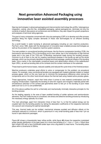
Chapter 1 - IntroductionA Chinese factory currently packages a variety of paper-clips into small boxes.Their means of operation is a group of about twelve women who do the job manually.The women stand around a table and take unfolded paper-clip boxes from a common pile.They proceed to fold the boxes, load one hundred clips into each, and pass them on forshipping. They package an estimated 70,000 boxes of paper-clips every day.There are several types of boxes for several types of paper-clips. The dimensionsof each type vary slightly, but they are all of similar shape. The most commondimensions of a folded box are 55 x 38 x 20 millimeters in length, width, and heightrespectively. The pictures below show one type of box in its partially folded andcompletely folded states.Figure 1: Paper-Clip Box4
The factory would like to increase the speed of packaging and decrease its costsas much as possible. Its current operating cost primarily consists of the salaries of thetwelve workers. The factory has requested that we automate their process as much aspossible in order to reduce the number of paid workers to the smallest number whilemaintaining or improving upon the speed of the current operation. Our team will conducta design of an automated paper-clip packaging machine. The machine will fold the boxesas well as load one hundred paper-clips into each box.From the beginning of our project, we constrained our design with seven taskspecifications. They are listed below.1. Machine is to be composed of conventional mechanisms2. Machine is to open box from initial flat position to open position.3. Machine is to fold and interlock bottom box tabs.4. Machine is to neatly load one hundred ( /- 1) paper-clips into each box.5. Machine is to fold and close top box tabs.6. Machine is to package boxes of paper-clips as quickly as possible.7. Machine is to cost less than its performance equal in human workersThe first order of business for our team is to conduct research on box folding ingeneral, existing processes, mechanisms, and folding methods. A clear understanding ofthe problem and any existing automated folding technology is the first step in developingour conceptual design.5
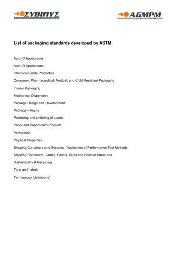
Chapter 2 - Background ResearchThe background research for this project occurred in three stages. We firstresearched preexisting designs to gain an understanding of commercially available boxfolding solutions. After completing a preliminary design and determining the mechanismwould be primarily linkage based, it became paramount to find a motor that would beable to drive the linkages and accurately pause at predetermined angle steps. The finalstage occurred when it became obvious that the folding and loading processes must takeplace at different locations. This realization forced us to consider different conveyingoptions to transport the partially folded boxes.Researching automated package assembling devices has opened our eyes to thereality that very few designs for complex box folding exist. To gain an understanding ofsolutions currently being implemented in industry, we have looked at box foldingapparati by Kluge; in particular the Small Box Automated Folder/Gluer. This machine isdesigned to fold a box that most closely resembles the box the paperclip factory currentlyuses. We dissected the processes of this machine and analyzed each of them. When theprocess is broken down and analyzed on a process flow diagram, it’s easy to discern thatthe whole operation is just a combination of two folding methods, hook and plow. Hookfolding is the simple process of using hooks, usually attached above the conveyor system,to catch on flaps of an unfolded box and force them in the opposite direction from whichthe stock is fed. This folding technique is commonly used to fold smaller flaps and flapsthat interlock to keep the box held in place. The second technique, plow folding, is aprocess in which flaps are fed into a ramp and forced in the opposing direction. In this6
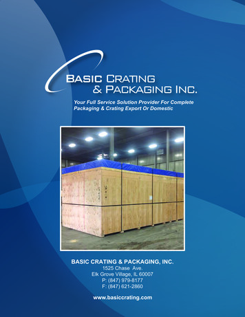
process the box needs to be held in place. This is done by plow shoes. This technique ofbox folding is usually reserved for large sections of the unfolded cardboard box orsections that need to be folded over each other.Figure 2: Kluge Small Box Automated Folder/GluerAnalyzing this process offers insight, but doesn’t provide a great foundation tobuild off of. Common to this machine and all other currently existing box foldingmachines are the use of glue and a human to complete complex folds. To incorporate boxloading into this process, the box would have to be transported to a totally differentmachine. In addition to the above flaws, the machine is largely inefficient. It takes upmuch space and is only capable of the simplest of folding operations. Based on theseconfounding factors, we feel it is best to start our design from scratch borrowing only thehook folding method for our simplest folds.7
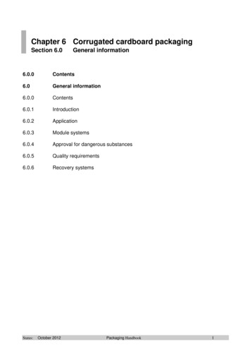
Figure 3: Process Flow Diagram of Kluge Small Box Automated Folder/GluerThe next step of background research was completed after our preliminary designwas completed and it was decided that our machine would be linkage based. To fill themotion requirement of pauses at predetermined angles, we concluded our machine wasbest served using step-motors. Step-motors are motors that offer accurate digital motioncontrol. Typically step-motors offer angle steps of 7.5 to 15 degrees. To research thesemotors we visited the Hankou business district of Wuhan, China to gather prices and alist of components necessary to implement the step-motors. In addition to the step-motoritself, a driver would also be needed in order program the starts and pauses at thespecified angle steps. We found the total package of step motor and driver would cost usroughly 360 RMB or 42.50 USD.8
Figure 4: Step Motor and Step Motor DriverThe final step of background research occurred when it became apparent that thebottom folding operation and loading operation must occur at different locations. Thisrealization forced us to consider different conveying options to transport the partiallyfolded boxes. Due to the boxes low weight and the precise positioning needed for foldingoperations to be completed, we felt it would be necessary to find a belt that would eitherhave a high grip and coefficient of friction or a belt that would limit the vibrationstransmitted to the box. Based on these characteristics we decided to use a belt constructedof Polyvinyl Chloride, or PVC, with a conveyor side surface featuring a quad/inverteddiamond woven pattern. The side offers a bare surface with low grip coefficient offriction 0.15. Although this belt doesn’t absorb many vibrations it has the highest griprating available, “Super”, and is capable of holding the box in the precise position neededto complete the remaining folding/loading operations.9
Figure 5: 3-Layer View of Conveyor 1) Top, conveying surface made from PVC woven in aquad/inverted diamond woven pattern 2) Solid Middle Layer made from PVC 3) Bottom, pulleysurface made of low friction Polyester Fiber10
Chapter 3 - Methodology & Design DescriptionThis section of our report explains the detailed structure of our project. Morespecifically, it will detail how we broke the process down into several discrete operationsand required motions and designed our machine accordingly.3.1 Folding Operations / Required MotionsUnlike the simpler boxes processed by existing automated packaging machines,our boxes require complex folds and several different types of folds. The complexity andvariation of the types of necessary folds call for the folding mechanisms to be veryprecise. A machine comprised of precise path generating linkages will not be able tohandle all the various box types and sizes without adjustment. We decided to design forone type of paper-clip box for this reason. Because of the boxes’ similar shape,interchangeable parts on the mechanisms can be designed to tailor them to the differentboxes. We chose to design the machine for the most common box. Its dimensions are 55x 38 x 20 millimeters in length, width, and height respectively.There are a total of eight folds necessary to completely process the box from itsinitial flat state to its closed state. The first fold is the transformation of the box from itsflat configuration to a 3-D, open configuration as shown below.11
Figure 6: Initial Folding OperationThis fold requires 90-degree parallelogram motion as the top profile of the box changesfrom a flat line to a rectangle.The next four folds are on the bottom of the box. Listed in folding order, they arethe back tab, the two symmetrical side tabs, and the front tab, which interlocks with theother three. The bottom tabs are shown below.Figure 7: Bottom Tabs and Folding Motions12
The back and side tabs must fold inward at 90 degrees and must be held in place until thefront tab interlocks with them and secures the bottom. These tabs can be folded bysynchronized linear manipulation. The front tab requires a vertical upward push(assuming the box is held upright) in order to interlock with the other three. This can beachieved by either two linear or one circular manipulation.The final three folds comprise the folding of the top of the box. There are twosymmetrical side tabs which can be folded in the same way as the back and side tabs onthe bottom of the box. They require linear manipulation. The top back tab is arguably themost complex fold. The top tabs are shown below.Figure 8: Top TabsThe creased section at the end of the back tab must be guided into the space between thefolded side tabs and the front of the box (the front being closest to the reader in thispicture). The folding of the back tab can be achieved by circular motion around the axis13
which joins the back tab and the back face of the box. The creased section at the end ofthe tab must be guided into its final position in some way.The operations and required motions for folding the box are tabulated below.12345678Folding OperationInitial Fold (Flat to 3-D)Botto
We chose to design the machine for the most common box. Its dimensions are 55 x 38 x 20 millimeters in length, width, and height respectively. There are a total of File Size: 1MBPage Count: 41