Transcription
2018 Annual Inspection of CCR UnitsLimestone Electric Generating StationJewett, TexasJanuary 2019Prepared ForNRG Texas Power LLCTony Dworaczyk, P.G.Senior Project ManagerJason Leik, P.E.Program Manager
Table of ContentsCertification. 2Table of Contents . 31.EXECUTIVE SUMMARY . 42.INTRODUCTION . 43.PURPOSE/OBJECTIVE . 44.CCR UNIT DESIGN & BACKGROUND . 54.1.UNIT 004 LANDFILL . 54.2.UNIT 003 SECONDARY E POND . 6CCR UNIT INSPECTION OBSERVATIONS & FINDINGS . 65.5.1.UNIT 004 LANDFILL . 65.1.1.CAPPED AREAS . 65.1.2.UNCAPPED LANDFILL AREAS . 75.1.3.AREAS UNDER CONSTRUCTION . 75.1.4.REVIEW OF CCR INVENTORY . 85.2.UNIT 003 SECONDARY E POND . 85.2.1.CHANGES IN GEOMETRY . 85.2.2.REVIEW OF EXISTING INSTRUMENTATION . 85.2.3.IMPOUNDMENT PARAMETERS . 85.2.4.VISUAL INDICATION OF ACTUAL OR POTENTIAL STRUCTURAL WEAKNESSES. 95.2.5.OTHER CHANGES . 96.REVIEW OF WEEKLY INSPECTIONS . 107.MAINTENANCE RECOMMENDATIONS . 108.CRITERIA . 109.LIMITATIONS . 1010.REFERENCES . 1011.CONCLUSIONS . 10FIGURES. 12PHOTOGRAPHS . 13
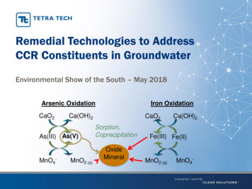
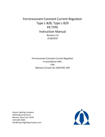
1. EXECUTIVE SUMMARYOn November 7, 2018, a representative of TRC Environmental Corporation (TRC) performed aninspection of the CCR units at the Limestone Generating Station, located at 3964 FM 39, Jewett, Texas.This work was performed to satisfy the requirement for an Annual Inspection by a qualified professionalengineer, as required by 40 CFR Part 257, the U.S. Environmental Protection Agency rule on Disposal ofCoal Combustion Residuals From Electric Utilities, which is referred to herein as the Federal CCR Rule.The applicable CCR landfill areas and impoundments (CCR units) were visually inspected by Mr. JasonLeik, P.E. (licensed in Texas). The inspection included performing a visual inspection of the applicableunits to identify areas requiring maintenance and showing signs of distress or malfunction of the CCRunits. TRC also reviewed the available documentation related to the CCR units at the LimestoneGenerating Station.This inspection evaluated: Unit 004 Landfill, andUnit 003 Secondary E Pond.TRC did not observe any evidence of ongoing or imminent failure of the landfill cell. There were nostructural deficiencies noted based on TRC’s observations.No maintenance items were identified in this annual inspection.Based on a review of available documents and the visual inspection, it is TRC’s opinion that Unit 004Landfill and Unit 003 Secondary E Pond have been designed, constructed, are currently operated, andare maintained in a manner that is consistent with and in accordance with recognized and generallyaccepted good engineering standards.2. INTRODUCTIONThis report presents the observations and findings of the 2018 annual inspection at the LimestoneGenerating Station. The Limestone Generating Station is located near Jewett, Texas. Specifically, themajority of the generating station is in Limestone County, while most of the CCR units are in FreestoneCounty. The power station is owned and operated by NRG Texas Power, LLC.The Limestone Generating Station includes two coal fired generating units with a total rated net capacityof 1,689 MW. The station is fueled by a mix of locally mined lignite and coal imported from the PowderRiver Basin in Wyoming.The general arrangement of the station is depicted in Figure 1.3. PURPOSE/OBJECTIVEThis document is prepared to provide compliance with the annual inspection requirements for CCR unitsas required by 40 CFR Part 257, the U.S. Environmental Protection Agency rule on Disposal of CoalCombustion Residuals From Electric Utilities (Reference 1). Specifically, Section 257.84(b) of the FederalCCR Rule pertains to the annual inspection requirements for CCR landfills.
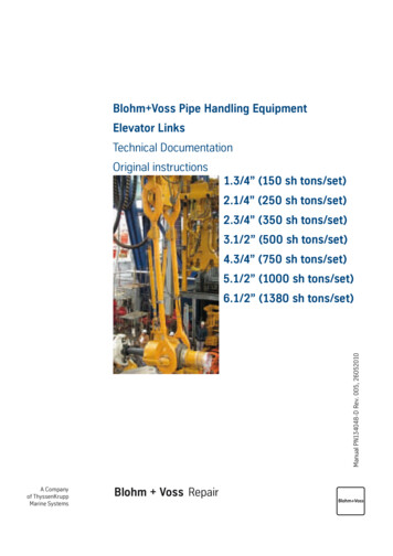
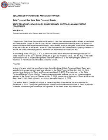
This document reports the annual inspection by a qualified professional engineer for all existing landfills(landfills that receive CCR material after October 19, 2015).The tasks included with this annual report are: Inspection of CCR units by a qualified professional engineer to evaluate if the design,construction, operation, and maintenance of the units are consistent with recognized andgenerally accepted good engineering standards.Review of available operational records and information concerning the status and condition ofthe CCR unit, including, but not limited to, files available in the operating record, and the resultsof weekly inspections by a qualified person;Visual inspection of the CCR unit to identify signs of distress or malfunction of the CCR unit andappurtenant structures.Preparation of this inspection report, as required by the CCR Rule, addresses the following:o Any changes in geometry of the CCR units since the previous annual inspection;o The approximate volume of CCR contained in the units at the time of inspection;o Any appearances of actual or potential structural weaknesses of the CCR units, inaddition to any existing conditions that are disrupting or have the potential to disruptthe operation and safety of the CCR units and appurtenant structures; ando Any other change(s) which may have affected the stability or operation of the CCR unitssince the previous annual inspection.NRG provided prior reports and design drawings as inputs to this inspection.4. CCR UNIT DESIGN & BACKGROUNDThe following CCR units are considered in this annual inspection: Unit 004 Landfill, andUnit 003 Secondary E Pond.The following paragraphs summarize the design and construction of these CCR units and evaluate theapplicability of the Federal CCR Rule to each CCR unit.4.1. UNIT 004 LANDFILLThe landfill is located east of FM 39. The landfill areas are designed as Class II Industrial Waste Landfillunder the criteria of the Texas Commission on Environmental Quality (TCEQ). The landfill is managedusing tracking areas indicated on Figure 2. These areas have no physical boundaries in the landfill andare hydraulically connected. The areas are considered to be in one of three stages. The stages for thetracking areas are capped, uncapped, and areas under construction.The landfill is constructed with a compacted clay liner with a minimum thickness of two feet. Areas thatare capped are capped with a compacted clay cover that is at least three feet thick. The landfill cap isthen covered with a minimum of one foot of topsoil to aid in proper vegetation protection for the cover.NRG reports that quality control and assurance testing was performed on the liner and cover.
Stormwater runoff is collected from capped areas with a perimeter ditch, while an interceptor ditchsurrounds the uncapped areas that contain CCR materials to intercept the stormwater runoff and anyCCR material that is eroded from the uncapped areas. This interceptor ditch drains into Pond 002.4.2. UNIT 003 SECONDARY E PONDThe Dewatered Sludge Disposal Area (Secondary E) Pond is also east of Highway 39 and is used as atreatment pond to stabilize the blowdown from the FGD system. Specifically, a fly ash product, StabileMix D, is mixed with wastewater from the FGD sludge thickener overflow to allow a chemical reaction tostabilize the FGD blowdown. The solidified material is then excavated from the pond, dewatered andtransported to the landfill for disposal.The Secondary E Pond is approximately 645 feet by 374 feet, and is bisected by an interior berm. Thepond bottom elevation is 476 feet and the perimeter berm height elevation is 485 feet. The dike toeelevation on the northernmost point is approximately 460 feet.Portions of the western and southern dikes have wider than typical dike crests. Portions of the southernand western dikes are 50 feet to 80 feet wide at the crest. The Secondary E Pond has a random fill(unclassified material) embankment with a 3 foot thick clay liner, for which construction quality controltesting has been performed.Since the Secondary E Pond is not fully incised, an annual inspection is required as documented in thesubsequent sections of this report.5. CCR UNIT INSPECTION OBSERVATIONS & FINDINGSOn November 7, 2018, Mr. Jason Leik, PE (Texas) along with Jason Scott of NRG, visually inspected theCCR units at the Limestone Generating Station. This visual inspection was performed to evaluate if thedesign, construction, operation, and maintenance of each applicable CCR unit is consistent withrecognized and generally accepted good engineering standards.5.1. UNIT 004 LANDFILLThe location and general arrangement of the landfill is depicted on Figure 2. The individual areasdiscussed in this report are also depicted on Figure 2.The landfill at the Limestone Station is a single CCR unit that has distinct areas for waste storage. For thisreport, the landfill is considered in three distinct life cycle stages: Landfill areas that have been filled, capped and vegetated are considered as “capped areas”,Landfill areas that currently receive CCR waste are considered “uncapped areas”, andLandfill areas where construction tasks are underway to place the clay liner for future CCRmaterial storage are considered to be “areas under construction”.5.1.1. CAPPED AREASAlthough landfill Areas 1, 2, 3, 5, 6, 9 and 10 are considered to be capped areas, exposed slopes of CCRmaterial are present in areas 1, 3, 6 and 10, where uncapped and areas under construction abut theexisting CCR material. The plateaued portion of the capped areas is well vegetated and generally wellgraded to prevent the impoundment of storm water as depicted in Photographs P‐1 through P‐4.
Drainage structures constructed to transfer storm water from the top of the capped areas down to theperimeter ditch consist of concrete lined rundown channels. One rundown channel is present in Area 1and a second in Area 5. These channels do exhibit some cracks but are considered to be in goodcondition as shown in Photograph P‐14.The rundown channels drain into a perimeter drainage ditch that flows around the west and south sidesof the landfill. Since the flow in these channels is storm water off the capped section of the landfill thathas not contacted CCR materials, this flow is separated from the perimeter interceptor ditch thatcollects contact water from uncapped areas of the landfill.The side slopes of the capped landfill areas are well vegetated and have appropriate interceptor ditchesas depicted in Photographs P‐1 through P‐4.Historical reports indicate that some water seepage was observed at the landfill toe near the southerncorner of Area 9. French drains were installed with drainage into a sump as indicated in previousreports. TRC did not observe any evidence of ongoing seepage.TRC did not observe visual evidence of slope instability in the capped portions of the landfill.5.1.2. UNCAPPED LANDFILL AREASAreas 4, 7, 8 and 11 are considered to be uncapped areas.Given the dynamic nature of active landfill areas, the comments presented herein represent TRC’sobservations made on November 6, 2018 and may or may not represent the conditions present at othertimes.The “work in progress” nature of active landfill areas result in exposed slopes of CCR material that willeither be capped, or where areas under construction will be filled and the existing CCR material slopewill be abutted by material placed in the new area. These exposed CCR slopes are encompassed by theinterceptor ditch that collects storm water runoff from uncapped areas and collects any CCR materialthat erodes or sloughs off the exposed CCR material slopes.These uncapped CCR slopes drain down into the interceptor ditch as shown in Photographs P‐6 and P‐7.The interceptor ditch directs the storm water runoff and any eroded CCR material to Pond 002.The haul road used to transport CCR materials to the top of the landfill is shown in Photograph P‐5.During the site inspection, no ruts were observed despite some rainfall in the preceding days,demonstrating that the CCR materials can be placed in a relatively stable condition.A typical view on the upper plateau level of the uncapped portion of the landfill is shown in PhotographsP‐5 and P‐6.Since this area is a work in progress and since the interceptor ditch is functioning to collect contactwater and eroded CCR materials, it is TRC’s opinion that this area is operated in accordance withgenerally accepted industry standards.5.1.3. AREAS UNDER CONSTRUCTIONAreas 12 through 20 are areas under construction.
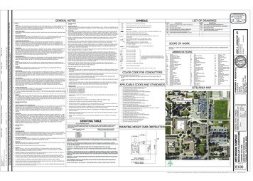
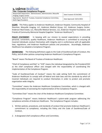
The earthwork activities to install the compacted clay liner in these areas is in various stages ofconstruction. Photograph P‐6 and P‐7 show Areas 13, 14, 17, 19 and 20 that have partially completedclay liners. Photograph P‐8 shows Area 12A where the clay liner protective cover is in place and a moredistant area of partially lined landfill area under construction.5.1.4. REVIEW OF CCR INVENTORYAs required by the Federal CCR Rule, the approximate volume of stored CCR in the landfill, as providedby NRG, is: Unit 004 Landfill: Approximately 30.02 Million cubic yards.Approximately 223,700 cubic yards were added to Unit 004 in 2018.5.2. UNIT 003 SECONDARY E PONDThe location and general arrangement of the Secondary E Pond are depicted on Figure 3.At the time of the TRC inspection, The Secondary E Pond was partially filled with water, with piles ofstabilized CCR material extending above the dike crest in the northern half of the impoundment. Theexposed CCR material, including excavated material that projects to approximately the same height asthe berm crest (Photographs P‐13 and P‐14) appears to be well stabilized rigid material.At the time of the TRC inspection, the freeboard appeared to be more than two feet on both the northand south sides. Based on these observations, TRC believes maintenance of pond level is satisfactory toallow sufficient freeboard for precipitation.5.2.1. CHANGES IN GEOMETRYFederal CCR Rule Reference: 40 CFR 257.83(b)(2)(i)Other than maintenance and solids removal from select impoundments, no noticeable changes ingeometry were observed while performing the visual inspection of dikes and CCR surfaceimpoundments.5.2.2. REVIEW OF EXISTING INSTRUMENTATIONFederal CCR Rule Reference: 40 CFR 257.83(b)(2)(ii)The Secondary E Pond outlet structure is equipped with a staff gauge. Maximum staff gauge readings,since the previous annual inspection, are reported in the next section.5.2.3. IMPOUNDMENT PARAMETERSFederal CCR Rule Reference: 40 CFR 257.83(b)(2)(iii), 257.83(b)(2)(iv), 257.83(b)(2)(v)Tables 1, 2 and 3 provide various measurable impoundment parameters required by 40 CFR257.83(b)(2)(iii) through (v) that have been recorded since the last annual inspection (November 8,2017) and at the time this annual inspection was performed (November 6, 2018).
TABLE 1: APPROXIMATE WATER DEPTH AND WATER SURFACE ELEVATIONOF CCR SURFACE IMPOUNDMENTSCCR SurfaceImpoundmentMinimumDepth1 (ft)MaximumDepth1 (ft)PresentDepth2 (ft)MinimumElevation1 (ft)MaximumElevation1 (ft)PresentElevation2 (ft)Unit 003Secondary EPond2.74.84.8478.7480.8480.8Notes:1) Since the previous annual inspection on November 8, 2017.2) At time of inspection on November 6, 2018.TABLE 2: APPROXIMATE AVERAGE CCR DEPTH AND AVERAGE CCR SURFACE ELEVATION WITHIN CCRSURFACE IMPOUNDMENTS1CCR SurfaceImpoundmentUnit 003Secondary EPondMinimumDepth2 (ft)MaximumDepth2 (ft)PresentDepth3 (ft)MinimumElevation2 (ft)MaximumElevation2 (ft)PresentElevation3 (ft)5.67.17.1481.6483.1483.1Notes:2) At time of inspection on November 6, 2018.3) Depths and elevations presented are averages over the aerial extent of each impoundment.4) Since the previous annual inspection on November 8, 2017.5) At time of inspection on November 6, 2018.TABLE 3: APPROXIMATE STORAGE CAPACITY AND VOLUME OF IMPOUNDED WATER AND CCR AT TIMEOF INSPECTIONCCR SurfaceImpoundmentUnit 003 Secondary E PondApproximate TotalAvailable StorageCapacity(ac‐ft)13.3Approximate ActualVolume of ImpoundedWater(ac‐ft)12Approximate ActualVolume of ImpoundedCCR(ac‐ft)19Note: The capacities utilized herein consider one foot of freeboard.5.2.4. VISUAL INDICATION OF ACTUAL OR POTENTIAL STRUCTURAL WEAKNESSESFederal CCR Rule Reference: 40 CFR 257.83(b)(2)(vi)TRC observed the exposed interior and exterior slopes, toes of slopes and crests of slopes for theapplicable CCR surface impoundments and did not observe any evidence of existing conditions that aredisrupting or could plausibly have the potential to disrupt the operation and safety of the applicable CCRsurface impoundments.5.2.5. OTHER CHANGESFederal CCR Rule Reference: 40 CFR 257.83(b)(2)(vii)No other changes were observed which may have affected the stability or operation of the applicableCCR impoundments since the prior annual inspection.
6. REVIEW OF WEEKLY INSPECTIONSThe weekly inspections by a qualified person (by NRG) have been performed and TRC has reviewed thereports. The inspections appear to be thorough and appropriately executed. Maintenance items wereidentified, resolved and documented in subsequent inspections.7. MAINTENANCE RECOMMENDATIONSAt the time of this inspection, there are no repairs needed that pose immediate operational or safetyconcerns for the CCR units inspected. Based on the observations made by TRC on November 7, 2018,TRC recommends that the current maintenance practices such as control of vegetation and feral hogs,and repair of minor erosion areas before they become significant, be continued.8. CRITERIAThis inspection been performed in accordance with the inspection requirements of the Federal CCR Rule(Reference 1) and generally accepted engineering practice. The TCEQ Guidelines for Operation andMaintenance of Dams in Texas (Reference 2) is considered to represent generally accepted practices andis considered to be an applicable criterion.9. LIMITATIONSGiven the visual nature of this inspection, it must be recognized that latent conditions may be presentthat are not visually evident.Given the work in progress nature of active pond and landfilling operations, this document onlyconsiders the conditions present at the time of the field inspection and information provided by NRG.10. REFERENCES1) 40 CFR Part 257, Hazardous and Solid Waste Management System: Disposal of Coal CombustionResiduals From Electric Utilities; Final Rule, April 17, 2015.2) Texas Commission on Environmental Quality, Guidelines for Operation and Maintenance of Dams inTexas, November 2006.3) Sargent & Lundy, Annual Inspection of CCR Impoundments and Landfill, January 15, 2016.11. CONCLUSIONSThis annual inspection considered the following CCR units: Unit 004 Landfill, andUnit 003 Secondary E Pond.TRC did not identify any evidence of ongoing or imminent failure of the CCR units. No structuraldeficiencies were noted during the 2018 inspection.Based on the review of available documents and the visual inspection, it is TRC’s opinion that Unit 004Landfill and Unit 003 Secondary E Pond have been designed, constructed, are currently operated, and
are maintained in a manner that is consistent with recognized and generally accepted good engineeringstandards.As discussed in Section 8, the ongoing maintenance efforts to promote grass vegetation and mitigatedamage from feral hogs should continue. No other maintenance items were identified in this annualinspection.
FIGURES
Unit 004 LandfillUnit 003Secondary E PondNFigure 1Location of CCR Landfill and ImpoundmentsLimestone StationNote: Aerial Image obtained using Google Earth Pro 7.3.2. Boundaries are approximate.700 Highlander BlvdSuite 210Arlington, Texas 76015
Figure 2Aerial View of Unit 004 LandfillLimestone StationNote: Aerial Image obtained using Google Earth Pro 7.3.2 and 2016 Annual Report Prepared by S&L.700 Highlander BlvdSuite 210Arlington, Texas 76015
Figure 3Aerial View of Unit 003 Secondary E PondLimestone StationNote: Aerial Image obtained using Google Earth Pro 7.3.2700 Highlander BlvdSuite 210Arlington, Texas 76015
PHOTOGRAPHS
Photographic Log – 2018 Limestone Annual InspectionPhotograph P‐1 Taken September 10, 2018 by Jason Leik, P.E. (during Location Certification)Unit 004 Landfill – Looking north along west base and exterior slope of berm along areas 2, 5 and 9.Photograph P‐2 Taken September 10, 2018 by Jason Leik, P.E. (during Location Certification)Unit 004 Landfill – Looking north along west crest and exterior slope of berm areas 2, 5 and 9.
Photographic Log – 2018 Limestone Annual InspectionPhotograph P‐3 Taken September 10, 2018 by Jason Leik, P.E. (during Location Certification)Unit 004 Landfill – Looking northeast across top of capped areas 2, 3, 5, 6, 9, and 10.Photograph P‐4 Taken September 10, 2018 by Jason Leik, P.E. (during Location Certification)Unit 004 Landfill – Looking east across top of capped areas 9 and 10.
Photographic Log – 2018 Limestone Annual InspectionPhotograph P‐5 Taken September 10, 2018 by Jason Leik, P.E. (during Location Certification)Unit 004 Landfill – Looking north up temporary carry down channel from uncapped area 11.Photograph P‐6 Taken September 10, 2018 by Jason Leik, P.E. (during Location Certification)Unit 004 Landfill – Looking north from peak of capped areas 9 and 10 towards areas 13, 14, and 17.
Photographic Log – 2018 Limestone Annual InspectionPhotograph P‐7 Taken September 10, 2018 by Jason Leik, P.E. (during Location Certification)Unit 004 Landfill – Looking east from peak of capped areas 9 and 10 towards areas 19 and 20.Photograph P‐8 Taken September 10, 2018 by Jason Leik, P.E. (during Location Certification)Unit 004 Landfill – Looking southeast from area 11 towards areas 12A.
Photographic Log – 2018 Limestone Annual InspectionPhotograph P‐9 Taken September 10, 2018 by Jason Leik, P.E. (during Location Certification)Unit 004 Landfill – Looking east from northwest base of capped areas 1.Photograph P‐10 Taken September 10, 2018 by Jason Leik, P.E. (during Location Certification)Unit 004 Landfill – Looking southeast east from west of area 1. Lined carry down trench visible.
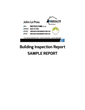
Photographic Log – 2018 Limestone Annual InspectionPhotograph P‐11 Taken November 6, 2018 by Jason Leik, P.E.Unit 003 Secondary E Pond – Looking southeast towards center of southern half of E Pond.Photograph P‐12 Taken November 6, 2018 by Jason Leik, P.E.Unit 003 Secondary E Pond – Looking south along top of and interior of west berm
Photographic Log – 2018 Limestone Annual InspectionPhotograph P‐13 Taken November 6, 2018 by Jason Leik, P.E.Unit 003 Secondary E Pond – Looking north along top of and interior of west bermPhotograph P‐14 Taken November 6, 2018 by Jason Leik, P.E.Unit 003 Secondary E Pond – Looking northeast towards center of north half of pond
The landfill is located east of FM 39. The landfill areas are designed as Class II Industrial Waste Landfill under the criteria of the Texas Commission on Environmental Quality (TCEQ). The landfill is managed using tracking areas indicated on Figure 2.