Transcription
CCR DESIGN CRITERIA DEMONSTRATIONMITCHELL LANDFILLMITCHELL POWER GENERATION PLANTMARSHALL COUNTY, WEST VIRGINIAPrepared For:KENTUCKY POWER COMPANYd/b/a AMERICAN ELECTRIC POWER, INC.COLUMBUS, OHIOPrepared By:CIVIL & ENVIRONMENTAL CONSULTANTS, INC.CINCINNATI, OHIOCEC Project 110-416FEBRUARY 2019
TABLE OF CONTENTSPage1.0OBJECTIVE .12.0BACKGROUND INFORMATION .22.1CCR Unit Location . 22.2Description Of CCR Unit. 32.2.1 Engineering Systems .32.2.1.1Groundwater Interceptor Drainage System .42.2.1.2Composite Liner System .42.2.1.3Leachate Collection System .42.2.1.4Surface Water Management System .52.2.2 Construction and Operational History .62.2.2.1Landfill Construction .62.2.2.2Landfill Operations .62.2.2.3Groundwater Monitoring .62.3Supporting Investigations And Documents . 73.0§257.70 DESIGN CRITERIA FOR NEW CCR LANDFILLS AND ANY LATERALEXPANSION OF A CCR LANDFILL .83.1§257.70 Rule Description . 83.2Information Supporting Rule Compliance . 83.2.1 Composite Liner.83.2.2 Leachate Collection System .84.0SUMMARY AND PROFESSIONAL ENGINEER CERTIFICATION .10LIST OF FIGURESFigure 1Figure 2Figure 3Site Location MapPlant and CCR Unit Location MapCCR Unit and Monitoring Wells-i-Mitchell Landfill CEC Project 110-416CCR Design Criteria DemonstrationFebruary 2019
1.0OBJECTIVEThis report has been prepared for Kentucky Power Company (KPC) d/b/a American ElectricPower, Inc. (AEP) to demonstrate that the Mitchell Landfill, a Coal Combustion Residuals (CCR)Unit by definition of the United States Environmental Protection Agency (EPA) CCR Rule whichhas been published in the Federal Register (FR) on April 17, 2015 and is an extension of the currentCode of Federal Rules (CFR) Title 40, Part 257 (§257), meets or exceeds the requirements DesignCriteria as defined in §257.70 for a composite liner and a leachate collection and removal system.While it is recognized that Phases 1 and 2 of the Mitchell Landfill are considered to be part of an“Existing Landfill” by definition of the CCR Rule, this report addressed compliance for both theexisting landfill phases (Phase 1 and 2) and future landfill phases (Phases 3 through 5). Becausethe future landfill phases have not begun construction prior to promulgation of the referenced Rule,they will be considered “Lateral Expansions” which must demonstrate compliance with §257.70and be certified (1) by a qualified professional engineer.(1)The terms certify and certification, as used herein, is defined as follows: “An Engineer’s Certification of Conditions is adeclaration of professional judgment. It does not constitute a warranty or guarantee expressed or implied, nor does it relieve anyother party of their responsibility to abide by contract documents, applicable codes, standards, regulations, or ordinances.”-1-Mitchell Landfill CEC Project 110-416CCR Design Criteria DemonstrationFebruary 2019
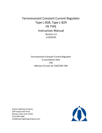
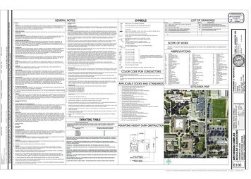
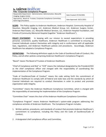
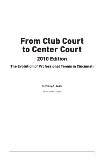
2.0BACKGROUND INFORMATIONKPC, a subsidiary of AEP, owns and operates the Mitchell Power Generation Plant. This facilityis located along West Virginia Route 2 near the City of Cresap, West Virginia (WV) as shown onFigure 1 – Site Location Map.The Mitchell Power Generation Plant uses bituminous coal as the primary fuel source for its twosteam-turbine electric generating units. Processes and equipment that control air emissions fromthe coal fired units generate CCRs comprised of fly ash, bottom ash, Chloride Purge Stream (CPS)Filter Cake material, and Flue Gas Desulfurization (FGD) gypsum. CCRs that are not beneficiallyused, primarily fly ash and gypsum, are disposed of at an off-site CCR Unit identified as theMitchell Landfill, which is a Class F solid waste landfill that is owned and operated by KPC.Mitchell Landfill is classified as a Class F Industrial Landfill Facility by the WV Department ofEnvironmental Protection (WVDEP) Division of Water and Waste Management (DWWM). Thelandfill was designed, permitted and operates in accordance with the WV Code of State Rules,Title 33, Series 1-Solid Waste Management Rule (33CSR1) and a NPDES Permit that wasapproved by the WVDEP on May 29, 2013 (Permit No. WV0116742). In addition, the WVDEPissued a State 401 Water Quality Certification (No. 12011) on January 10, 2013 and the U.S. ArmyCorps of Engineers (USACE) issued a Clean Water Act Section 404 permit (No. 2011-1499) onFebruary 25, 2013. These permits provide the regulatory authority to impact aquatic resourcesincluding wetlands, streams and a pond.The following subsections provide a summary of the Mitchell Landfill CCR Unit.2.1CCR UNIT LOCATIONMitchell Landfill is located along Gatts Ridge Road (Marshall County Road 72), approximately2 miles north of the intersection with County Road 74 (about 2 miles due east of the MitchellPower Generation Plant). The approximate location of Mitchell Landfill is depicted on Figure 1 –Site Location Map and Figure 2 – Plant and CCR Unit Location Map. The center of Mitchell-2-Mitchell Landfill CEC Project 110-416CCR Design Criteria DemonstrationFebruary 2019
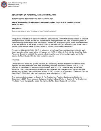
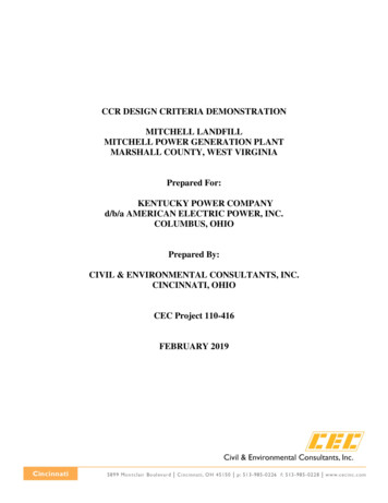
Landfill is located at the following coordinates: Latitude: 39 degrees, 49 minutes, 37 seconds North. Longitude: 80 degrees, 46 minutes, 32 seconds West.2.2DESCRIPTION OF CCR UNITMitchell Landfill provides a maximum disposal capacity of about 10 million cubic yards of excessCCR produced from the Mitchell Power Generating Plant that is not beneficially reused. Theoverall landfill boundary comprises about 169.6 acres with CCR being placed within a footprintof 57.6 acres (the CCR Unit disposal area is depicted on Figure 2 – Plant and CCR Unit LocationMap). The landfill will be operated in 5 phases with Phases 1 through 4 completing the maximumCCR Unit disposal footprint and Phase 5 comprising CCR placement atop the first four phases.Figure 3 – CCR Unit and Monitoring Wells, depicts the approximate boundary of the 5 phases.The expected total life of the landfill is 24 years, based on the current estimated average yearlyCCR production rates and beneficial use quantities.In addition to the CCR disposal footprint, the CCR Unit includes several appurtenant structuresthat include: 1) a perimeter haul road; 2) a leachate storage pond; 3) three stormwater ponds(identified as South, West and North Ponds); and, 4) a Maintenance Building. Figure 3 – CCRUnit and Monitoring Wells, depicts the CCR Unit boundary, the landfill disposal footprint, andthe associated appurtenant structures.2.2.1Engineering SystemsThe landfill was designed and constructed to protect the environment in accordance with theWVDEP Class F Industrial Landfill and has demonstrated compliance with the CCR Rulerequirements. To meet these requirements, Mitchell Landfill includes several engineering controlswhich include: 1) a groundwater interceptor drainage system; 2) a composite liner system; 3) aleachate collection system; and, 4) a surface water management system. These engineeringsystems are summarized below.-3-Mitchell Landfill CEC Project 110-416CCR Design Criteria DemonstrationFebruary 2019
2.2.1.1 Groundwater Interceptor Drainage SystemThe groundwater interceptor drainage system for the landfill is a combination of pipes andaggregate drains that collect and direct groundwater from beneath the liner system to a dischargepoint beyond the landfill limits. This system is designed to accommodate natural groundwatervolumes and the potential increased groundwater volume that may result from future hydrostaticconditions associated with future pool level increases for the Conner Run Impoundment that ispositioned in the adjacent valley west of the landfill.2.2.1.2 Composite Liner SystemAn impermeable barrier is located at the base of the Mitchell Landfill CCR Unit that is protectiveof groundwater and complies with the applicable WVDEP performance standards for a Class FIndustrial Landfill Facility and the CCR Rule. The bottom elevations of the impermeablebarrier/composite liner provide the required separation from bedrock, the seasonal high watertable, and the uppermost significant aquifer. The composite liner system is comprised of thefollowing (from top to bottom): 30-mil PVC geomembrane; Geosynthetic Clay Liner (GCL); A minimum 6-inch thick layer of compacted subbase soil; and, Structural fill or isolation layer soil as needed to provide the minimum separation fromgroundwater and bedrock.2.2.1.3 Leachate Collection SystemMitchell Landfill has a leachate collection system that conveys leachate collected above thecomposite liner system via gravity flow to a lift station that pumps the leachate to a storage pond(denoted as the Leachate Storage Pond) via a force main. Stormwater runoff from within activelandfill areas is directed to the leachate collection layer within the landfill via vertical aggregatedrains (denoted as chimney drains). The leachate collection layer conveys both stormwater from-4-Mitchell Landfill CEC Project 110-416CCR Design Criteria DemonstrationFebruary 2019
the chimney drains and leachate that seeps through the CCR placed in the landfill and transportsthe combined flow to the lift station. The leachate collection system maintains a leachate head onthe composite liner system of 10 inches or less. The locations of the lift station and LeachateStorage Pond are identified on Figure 3 - CCR Unit and Monitoring Wells.The leachate collection system within the waste placement limits for (leachate collection layer)consists of the following: Permeable Drainage Layer – comprised of a drainage geocomposite that covers the entirebottom of Phase 1 and 2 of the landfill and an 18-inch thick Granular Drainage Layer coversthe bottom of Phases 3 and 4 of the landfill. Both drainage layers are to be constructeddirectly above the composite liner system. Leachate Collection Pipes – perforated HDPE pipes, surrounded by non-calcareous coarseaggregate and nonwoven, needle-punched geotextile, are constructed atop the drainagegeocomposite or within the Granular Drainage Layer. These leachate collection pipesconvey leachate collected at the base of the landfill to the lift station via gravity drainage,which is then pumped (via a force main) to the Leachate Storage Pond.Leachate collected and transferred to the Leachate Storage Pond is beneficially reused for dustsuppression within landfill waste limits, moisture conditioning of fly ash during compactionprocedures or moisture conditioning at the fly ash silo storage facility. Any leachate that is notbeneficially reused is transported to the Mitchell Plant Wastewater Treatment Bottom Ash PondComplex for treatment prior to discharge into the Ohio River.2.2.1.4 Surface Water Management SystemManagement of surface water that is not in contact with CCR placed in the landfill is accomplishedby collection and conveyance of runoff to three stormwater detention basins: 1) South Pond;2) West Pond; and, 3) East Pond. The South and West Ponds are utilized through all phases of thelandfill life, and the East Pond is utilized in Phase 3 through Phase 5. The three ponds are depictedon Figure 3 - CCR Unit and Monitoring Wells.Site runoff generated from both un-stabilized and stabilized constructed areas (i.e., constructionareas, stockpiles, temporary landfill cover, and permanent landfill cover) is conveyed to the-5-Mitchell Landfill CEC Project 110-416CCR Design Criteria DemonstrationFebruary 2019
stormwater detention basins via drainage channels and pipes. The collection, conveyance andbasins are designed to meet the required criteria in the referenced WVDEP regulations. Thestormwater conveyed to the basins is detained and released through a non-clogging dewateringskimmer device that allows settling of suspended solids and evacuation of the stored volume ofwater within a seven to eight day period.2.2.2Construction and Operational History2.2.2.1 Landfill ConstructionConstruction of Mitchell Landfill was initiated in 2013 and Phases 1A, 1B, 2A, and 2B have beencompleted. The landfill construction was performed in accordance with the NPDES/Solid WastePermit, the construction drawings, technical specifications, and the Quality Assurance and QualityControl (QA/QC) Plan. Certification Reports were prepared and submitted to WVDEP that provideconfirmation and documentation that the construction of Phases 1A, 1B, 2A, and 2B wasperformed in accordance with the design and permit requirements.Construction of the Phase 3 liner system is tentatively scheduled to begin in 2019.2.2.2.2 Landfill OperationsMitchell Landfill began operation in July 2014 and is currently receiving CCRs from MitchellPower Generation Plant. Landfill operations, construction and monitoring are being performed inaccordance with the NPDES/Solid Waste Permit.2.2.2.3 Groundwater MonitoringBackground groundwater quality monitoring began in February 2012 and was completed inDecember 2014. Operational groundwater monitoring is conducted semi-annually in accordancewith the Mitchell Landfill Operating Record and Groundwater Monitoring Plan. Groundwaterquality results for key indicator parameters are statistical analyzed as part of each semi-annualgroundwater monitoring event and included as part of the Annual Operation Report.-6-Mitchell Landfill CEC Project 110-416CCR Design Criteria DemonstrationFebruary 2019
2.3SUPPORTING INVESTIGATIONS AND DOCUMENTSCEC has reviewed the following documents for evaluation of compliance with the CCR RuleDesign Criteria:1. Solid Waste/NPDES Permit Application, Mitchell Landfill, Mitchell Plant, Cresap, WestVirginia, Prepared for American Electric Power, Prepared by Civil & EnvironmentalConsultants, Inc., CEC Project No. 110-416, April 12, 2012.2. CCR Landfill Restriction Demonstration, Mitchell Landfill, Marshall County, WestVirginia, Report to Kentucky Power Company d/b/a/ American Electric Power, 1 RiversidePlaza, Columbus, Ohio 43215, Prepared by Civil & Environmental Consultants, CECProject No. 110-416, November 2015.3. Letter - Leachate Collection Layer Design Alternate, AEP / Mitchell Landfill, prepared byCivil & Environmental Consultants, Inc., CEC Project No. 110-416-7522, February 8,2019.-7-Mitchell Landfill CEC Project 110-416CCR Design Criteria DemonstrationFebruary 2019
3.0§257.70 DESIGN CRITERIA FOR NEW CCR LANDFILLS AND ANY LATERALEXPANSION OF A CCR LANDFILL3.1§257.70 RULE DESCRIPTION40 CFR 257.70(a)(1) states:New CCR landfills and any lateral expansion of a CCR landfill must be designed, constructed,operated, and maintained with either a composite liner that meets the requirements of paragraph(b) of this section or an alternative composite liner that meets the requirements in paragraph (c) ofthis section, and a leachate collection and removal system that meets the requirements of paragraph(d) of this section.3.2INFORMATION SUPPORTING RULE COMPLIANCE3.2.1Composite LinerThe composite liner system for Phases 1 through 4 of Mitchell Landfill consists of an upper andlower impermeable component. The upper component consists of a 30-mil PVC geomembraneand the lower component consists of a GCL with a hydraulic conductivity of no more than3.4 x 10-9 cm/sec. The upper component will be installed in direct and uniform contact with thelower component. In accordance with §257.70 (c) (1) and (2), a Liner Hydraulic EquivalencyDemonstration Calculation was prepared by a professional engineer to confirm that the liquid flowrate through the lower component of the alternative composite liner is no greater than the liquidflow rate through two feet of compacted soil with a hydraulic conductivity of 1 x 10⁻⁷ cm/sec. Thedesign calculations supporting the WVDEP PTI and the construction documents, including theQA/QC Plan, include design criteria and material specifications necessary to meet §257.70 (b)(1-4). Based on this demonstration, the composite liner system meets the design requirements foran alternate composite liner as outlined in §257.70 (c) (1-3).3.2.2Leachate Collection SystemThe leachate collection and removal system for the Mitchell Landfill consists of a permeabledrainage layer and pipe network directly atop the 30-mil PVC liner/GCL composite liner system.-8-Mitchell Landfill CEC Project 110-416CCR Design Criteria DemonstrationFebruary 2019
The drainage layer is comprised of: 1) a drainage geocomposite (Phases 1 and 2); and, 2) an18-inch thick drainage aggregate layer (Phases 3 and 4). Perforated HDPE pipes are installed atopthe drainage geocomposite and within the aggregate drainage layer at designated spacing and lowpoints to collect and convey leachate from the permeable drainage layer(s) to the landfill wastelimits, at which solid HDPE pipes convey the collected leachate to the designated leachate storageand treatment. Chimney drains, directly connected into the HDPE collection pipe system, are alsoincluded to collect surface water and better promote drainage of the waste materials during theactive life of the landfill.The leachate collection system design, including the materialspecifications and QA/QC Plan, establishes a permeable collection layer and piping network thatwill collect and remove leachate from the landfill during the active life and post-closure care periodmeeting the design requirements outlined in §257.70 (d) (1-3).-9-Mitchell Landfill CEC Project 110-416CCR Design Criteria DemonstrationFebruary 2019
4.0SUMMARY AND PROFESSIONAL ENGINEER CERTIFICATIONThis CCR Design Criteria Demonstration addresses compliance with both the existing (Phase 1and 2) and future landfill phases (Phases 3 through 5) that have not begun construction prior topromulgation of the referenced CCR Rule and are be considered “Lateral Expansions”. Insummary, Mitchell Landfill has been designed and constructed to meet the CCR Rule DesignCriteriarequirements included in §257.70. Section 3.0 of this report provides supportinginformation and conclusions demonstrating the design criteria has been met.In accordance with §257.70 (e), this CCR Design Criteria Demonstration provides confirmationby a qualified professional engineer and that there is sufficient information to demonstrate that theexisting Mitchell Landfill, and future expansion phases, meet the Design Criteria requirementsstated in 40 CFR 257.70 (a) through (e).-10-Mitchell Landfill CEC Project 110-416CCR Design Criteria DemonstrationFebruary 2019
FIGURES
OohiRerivOhioCounty, WVWashingCounty,BelmontCounty, OHMoundsville, WVMarshallCounty, WVCresap, WV GreeneCounty, PAGraysville, WVMonroeCounty, 110416 MitchellLandfill t7522 Figure1.mxd - 1/3/2019 - 11:18:40 AMMitchell PowerGeneration PlantMitchellLandfillWetzelCounty, WV Approximate Site Location0QUADRANGLE LOCATION124SOURCE: ARCGIS ONLINE MAP SERVICE: HTTP://GOTO.ARCGISONLINE.COM/MAPS/USA TOPO MAPS, LAST ACCESSED: 1/3/2019Civil & Environmental Consultants, Inc.5899 Montclair Boulevard - Cincinnati, OH 45150513-985-0226 - 800-759-5614www.cecinc.comDRAWN BY:DATE:MHSJANUARY 03, 2019CHECKED BY:DWG SCALE:APA1 " 4 miles6MilesAMERICAN ELECTRIC POWERMITCHELL LANDFILLMITCHELL POWER GENERATION PLANTMARSHALL COUNTY, WEST VIRGINIACCR DESIGN CRITERIA DEMONSTRATIONSITE LOCATION MAPAPPROVED BY:PROJECT NO:APA*110-416-7522FIGURE NO:1Signature on File *
II!lNORTHMitchellPower Plant\\svr-cinci\projects\2011\110-416\-GIS\110416 MitchellLandfill t7522 Figure2.mxd - 1/3/2019 - 11:26:01 AMMitchellLandfill1,00001,0002,000FeetLegendLimits of WasteQUADRANGLE LOCATIONSOURCE: PORTION OF THE USGS 7.5-MINUTE SERIES TOPOGRAPHIC QUADRANGLE MAP - GLEN EASTON, WV - 1978 AND POWHATAN POINT, WV - 1978.Civil & Environmental Consultants, Inc.DRAWN BY:DATE:5899 Montclair Boulevard - Cincinnati, OH 45150513-985-0226 - 800-759-5614www.cecinc.comMHSJANUARY 03, 2019CHECKED BY:DWG SCALE:APA1 " 2,000 'AMERICAN ELECTRIC POWERMITCHELL LANDFILLMITCHELL POWER GENERATION PLANTMARSHALL COUNTY, WEST VIRGINIACCR DESIGN CRITERIA DEMONSTRATIONPLANT AND CCR UNIT LOCATION MAPAPPROVED BY:PROJECT NO:APA*110-416-7522FIGURE NO:2Signature on File *
AST PONDPHASE 3SB-23MW1104FMW1104RDATETP-E9WEST PONDPHASE 111TP-E10TP-15MAINTENANCEBUILDINGPHASE 1TP-E7TP-E8GDESCRIPTIONREVISION RECORDTP-E5TP-E6TP-E4TP-E3TP-E2TPF5899 Montclair Blvd. - Cincinnati, OH 45150513-985-0226 · 800-759-5614SB-23MW1104FMW1104RPHASE 2LANDFILLENTRANCEHAUL ROADPHASE 3PHASE 5TS RIDGE ROADPHASE 1EGATEwww.cecinc.comFNOHAUL ROADPHASE 2PHASE 3HAUL ROADPHASE 1CCR DESIGN CRITERIA DEMONSTRATIONCCR UNIT AND MONITORING WELLSNORTHDRAWN BY:DATE:CONTOUR INTERVAL 10 FEETBJANUARY 2019BAFIGURE NO.:387654321APAZJIB-1501MW1501FMW1501RSOUTH PONDPHASE 1CAPPROVED MW1101RMW1101HPROJECT NO:B-1502MW1502RAPALEACHATELIFT STATIONCHECKED BY:LEACHATESTORAGE PONDPHASE 1DAS NOTEDDDWG SCALE:PHASE 4AMERICAN ELECTRIC POWERMITCHELL LANDFILLMITCHELL POWER GENERATION PLANTMARSHALL COUNTY, WEST VIRGINIASB-07MW1102BMW1102FMW1102RA
CCR Unit disposal footprint and Phase comprising CCR placement 5 atop the first four phases. Figure 3 CCR Unit and Monitoring Wells- , depicts the approximate boundary of the 5 phases. The expected total life of the landfill is 24 years, based on the current estimated average yearly CCR production rates and beneficial use quantities.