Transcription
WINEGARD TRAV’LERTMAutomatic Multi-Satellite TV AntennaModelsSK-1000 DISH 1000SK-3003 DIRECTV TRIPLE FEEDINSTALLATION MANUALMade in the U.S.A.SK-3003SK-1000Winegard Company 3000 Kirkwood St. Burlington, IA 52601-2000319/754-0600 FAX 319/754-0787 www.winegard.comPrinted in U.S.A. Winegard Company 2007 2452126 Rev. 1/08
Congratulations!You have selected the Winegard TRAV’LER Automatic Multi-Satellite TV Antenna. The TRAV’LERantenna will deliver the ability to view up to five satellites at the same time with unmatched signalstrength, the lowest travel height on the market, maximum HD capabilities and easy to use functionality– just like you get at home. This manual provides important information on the installation and operationof your TRAV’LER Interface Box. Please take time to read the manual in it’s entirety before installing oroperating your antenna.Icons appearing in the manual are used for important information and helpful tips.Alert indicates important information regardingproduct use, product specifications or procedures.Important tip offers helpful suggestions orrefers you to a related topic in the manual.Recommended Receivers:The Winegard TRAV’LER Automatic Multi-Satellite TV Antenna will work with any DISH Network or DIRECTV receiver currently in production. However, we recommend:- DISH Network : models 311 and 211- DIRECTV: models D11 and H20Each receiver will require at least one coax cable. Refer to receiver manual for wiring details.NOTE: DISH Network’s primary HD satellite, the 129 , may not be available in all areas.Check with your programming provider for coverage in certain areas.The SK-1000 is compatible with all DISH Network Dish Pro Plus Receivers and the SK-3003 is compatible with all DIRECTV Triple Feed Receivers. Consult your receiver manual or www.winegard.com ifyou have any questions about whether your receiver is compatible.Before you begin please make sure you have received all necessary parts to properly install and operate your TRAV’LER antenna.- Installation/Operation Manual- Mount Base with 30’ Cable - Power/Control Cable- TRAV’LER Interface Box- Reflector, LNBF & Feed Arm- 24” AC power cord- TRAV’LER Power supply- Gray Coax Cable 30’- Black Coax Cable 30’- Mounting Hardware bag- Cable Entry Hardware bagSelecting a Location for the TRAV’LER AntennaBefore removing the TRAV’LER antenna from its box, check with your RV Dealer or manufacturer. YourRV may be pre-wired or have a reinforced area for this system. DO NOT install in a location where agap of 3/16” or more exists, as it may damage the roof. See diagram at top of page 3.INSTALLATION2
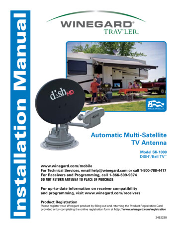
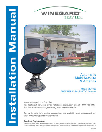
Plan your entire installation beforeyou start. Determine the location ofall of your equipment and make surecable and wires are long enough toreach their destination points.3/16”You must find a location on the roof that provides adequate space to allow the TRAV’LER antenna tooperate. The TRAV’LER antenna has a Front and Back and must be mounted correctly to avoid damage to the TRAV’LER antenna or the coach. The antenna must be mounted /-3 degrees of levelor the system may not function correctly. The Transition plate for the TRAV’LER unit is marked“FRONT” and “BACK”. See Figure 1.FIGURE 1!FRONT OF RVTRANSITIONPLATEWinegard is NOT liable for damage, expenses, or injury causedby improper installation.MountParallel toCenter Lineof CoachOnce you have checked for this:1. Choose a location on the roof of the RV that will allow the dish to raise and rotate without interference from other roof mounted equipment. The TRAV’LER antenna may only be mounted parallel tothe centerline of the coach.FIGURE 2FRONT OF RVMount Parallel toCenter Line of Coach2. The minimum roof space required for the TRAV’LER antenna is 43” L x 24” W.a. The operational space requires that no obstructions taller than 8 inches be mounted withina 62” diameter circle from the center of the unit.3INSTALLATION
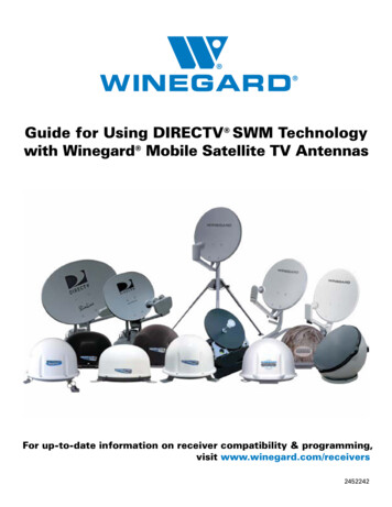
3. The unit must be within 3 of level for best operation.4. Make sure that the location offers enough support to attach the TRAV’LER antenna securely.5. Find a well ventilated location with a 110 V outlet for the TRAV’LER Interface inside the vehicle.Make sure to clean the installation area before you begin.You will want to decide where the wires will enter the vehicle. One coax cable per receiver and a controlcable will need to be run into the vehicle.!Warning: Do not run the wires through the striped area shown. Consult your receivermanual for specifics in the diagram.FIGURE 313 inches20 inchesNOTE: Anything in the striped area will interfere with the operation of the TRAV’LER antennaand may cause damage to the object or the TRAV’LER antenna.TRAV’LER Mount InstallationVerify that the “FRONT” of the transition plate is facing the front of the vehicle then place the TRAV’LERantenna mount on the roof where you plan to install it and mark the screw holes so you can see them.Move the TRAV’LER mount out of the installation area. It is recommended that you don’t pre-drill theholes.Use a solid bead of sealant to connect these marks in the shape of the base.Replace the TRAV’LER antenna and screw it to the roof. Check with your vehicle manufacturer for anyspecial screw requirements before using the supplied screws.INSTALLATION4
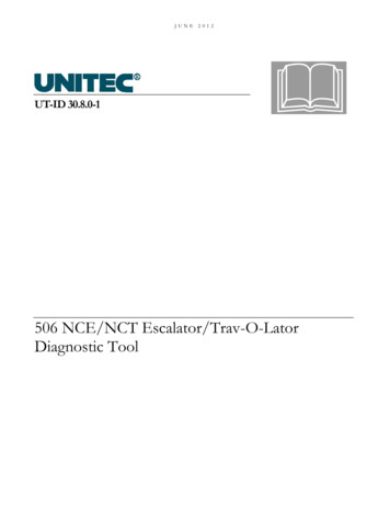
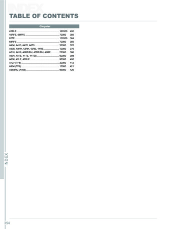
FIGURE 4DO NOT SEAL!LIP OFTRANSITIONPLATEWARNING: DO NOT cut anywires when you drill the holefor your cables.SEALRun a solid bead of sealant around the transition plate, making sure to cover each screw head. Becareful not to get any sealant above the lip of the transition plate. See diagram of transition plate.Cable Entry Plate Installation:Winegard recommends installing the Accessory DetectCable, this can provide aemergency stow function.Decide the best location for the cables to enter the vehicle.You will need to run:A coax directly to each receiver location.A control cable to the TRAV’LER Interface box.Drill a 1/2” hole in the roof and push the required wires through. (Installations for multiple receivers mayrequire a larger hole or multiple holes as each receiver requires a dedicated coax cable.) Each receiverwill require at least one coax cable. See receiver manual for wiring details.Place the cable entry plate supplied in hardware bag over the hole and cables. Screw the plate in placeand seal the plate and screw holes with approved sealant (not included).Depending on the length of the cable on the roof, you may need to use cable clamps between the unitand your cable entry plate. Clamping every 12-16” should eliminate any unnecessary cable movement.FIGURE 5OVERALL INSTALLATION DRAWINGFRONT OF RVFor best results, use TV1 for the receiver that willbe most active.POWERSUPPLYAIDUBPOWERCENTRY PLATERECEIVERTV 1RECEIVERRECEIVERTV 3TV 25INSTALLATION
Cable installation:Connect the control cable and power cable to the back of the TRAV’LER Interface box as shown below. Note:For cable runs longer than 25’ an extension may be purchased. Do not exceed 50’ of cable.Power Control Cable FIGURE 5Attach the TRAV’LER control cable to the TRAV’LER Interface Box, as shown in Figure 5.Attach the output cable from the Power supply to the TRAV’LER Interface Box. See above.Finally, connect a coax cable from the TRAV’LER mount to each of the receivers being used with the TRAV’LERAutomatic Satellite Dish. See Appendix for information on properly installing a Hex Connector.Find a location to plug in the TRAV’LER Power supply and plug it in.Reflector Installation:Once the wires are run and the sealant has started to cure:Check to be sure that there is nothing above the TRAV’LER that might prevent it from raising. You will need atleast 40” of clearance above the TRAV’LER Mount to ensure that you have room to install the reflector.Steps 1-7 explain how to use the TRAV’LER Interface box to raise the mount to install the reflector.1. Press [POWER] and hold for 1 second to turn “ON” the TRAV’LER Interface Box. Wait untilthe Interface Box finishes “connecting to antenna”.UPDATE: You have “10 SECONDS” to do Step 2 or, the “Search Routine” starts. (See NOTE)2. Press [ENTER] and hold for 2 seconds or until the unit enters its Menu Mode.3. Press [SELECT] to move the asterisk to [INSTALLATION].4. Press [ENTER]. You will be asked to provide a code to enter the Installation Menu.5. Press [ENTER] 4 times to enter code 0000.6. Press [SELECT] to move the asterisk to [RAISE DISH].7. Press [ENTER] the TRAV’LER mount will raise up about half way, to make it possible to attachthe reflector.NOTE: If the TRAV’LER enters the “Search Routine” you can still enter the “Menu Mode”. See steps A & B.If the TRAV’LER Mount rises past 1/2 way before [RAISE DISH] is selected (See Step 6) theTRAV’LER will hit its Upper Hard Stop and “Motor Stall” appears. This is Normal!The “Motor Stall” means the TRAV’LER is all the way up & mount can rise no more. There aretwo easy ways to clear the “Motor Stall”. Either is okay. (See Steps A & B).A. Press [ENTER] the TRAV’LER will return to the “Installation Menu” orB. Press [POWER] the TRAV’LER will stow and turn “OFF” (Restart at Step 1).INSTALLATION6
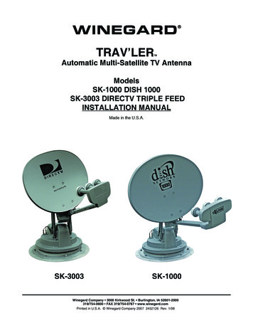
WARNING: Pay attention to these Pinch Points as the antenna raises.FIGURE 6FIGURE 7Pinch PointsPinch PointPinchPointUsing the (4) bolts and nuts provided, attach the reflector to the mounting bracket.Press [POWER] to lower the antenna to the travel position. Note: The nuts securing the dish should betightened to 6-8 lb.ft.Receiver Setup:If you are not able to see all of your channels or the receiver displays an error, it may be necessary togo through the receiver set up once the TRAV’LER has finished a successful search.For DISH Network users:First, access your Signal Strength screen: Press MENU button. Select “System Setup” (6), “Installation” (1), “Point Dish/Signal” (1).Next perform a Check Switch: You won’t need to perform this test again, unless check switch is performed on another dish.1. From the “Point Dish/Signal Meter” Screen, use arrow buttons on remote to select “Check Switch”.2. Select “Test” on this screen to begin.3. This test should find A DPP 1K.2 switch.4. Select “Cancel” from each menu until you are watching television.Note: The Procedure may change subtly from model to model, please consult your receiver manual fordetails.For DIRECTV users:Please refer to your Receiver Manual to enter the Guided Setup, using oval dish three satellite locations for antenna type.7INSTALLATION
Appendix:Making the Right Connectionwith FC-5910 Hex ConnectorsMaking a coaxial cable connection is critical. If you have thebasic technique right you can modify it to your own personaltaste. Whether you use a knife, stripping tool or diagonal cutter,the important thing is to make a good clean cut. A hex crimpingtool is required for hex connectors, for maximum RF transmission.As mentioned before, the choice of tools is yours. Be sure youdo a precise job. Failure to do so can cost you time and moneyin trying to locate a system problem.Slide FC -5910 connector onto coax.Trim off excess braid.Cut the cable flush. Strip the outerjacket off 1/2”, then trim the dielectricby cutting partially thru. DO NOTNICK THE CENTER CONDUCTOR!Twist and pull off leaving a 1/2” minumum of exposed center conductor.IN HOT WEATHER: Trim off centerconductor leaving 3/16” beyond theconnector. The center conductorexpands at higher temperatures. Ifa little extra is not provided, it maycontract enough in the winter to create an open connection and result inloss of picture.Look into end of connector to makesure no braid or aluminum foil touchesor has the possibility of touching thecenter conductor. Shorting can resultif either comes in contact with centerconductor. Close crimping tool makingcorrect crimp.!DO NOT paint this antenna!Painting the TRAV’LER antennawill void your warranty.INSTALLATION8Remove additional 1/4” of the outerjacket.Pull the braid away from thedielectric and fold over the jacket.If there’s any residue on the centerconductor scrape off with non-metallicobject.IN COLD WEATHER OR INDOORS:Trim off center conductor leaving itextended 1/16” of an inch beyond theconnector. (Use diagonal pliers forcutting center conductor).
WINEGARD MOBILE PRODUCTS LIMITED WARRANTY(2 YEARS PARTS; 1 YEAR LABOR)Winegard Company warrants this product against defects in materials or workmanship for a period of two (2) yearsfrom the date of original purchase. During year one (1) of such warranty, Winegard Company will also pay authorizedlabor costs to an authorized Winegard dealer to repair or replace defective products. No warranty claim will be honoredunless at the time the claim is made, Customer presents proof of purchase to an authorized Winegard dealer (to locatethe nearest authorized Winegard dealer, contact Winegard Company, 3000 Kirkwood Street, Burlington, Iowa 52601,Telephone 319-754-0600 or visit www.winegard.com). Customer must provide proof of purchase with a dated sales receiptfor the Winegard product to verify the product is under warranty. If the date of purchase cannot be verified, the warrantyperiod shall be considered to begin thirty (30) days after the date of manufacture.If a defect in material or workmanship is discovered, Customer may take the product to an authorized Winegard dealerfor service. Customer must provide proof of purchase to verify the product is under warranty. If the product is brought toan authorized Winegard dealer for service prior to expiration of year one (1) of the warranty period and a defect in materialor workmanship is verified by Winegard Technical Services, Winegard Company will cover the Winegard dealer’s laborcharges for warranty service. The Winegard dealer must contact Winegard Technical Services in advance for pre-approvalof the service. Approval of the service is at the sole discretion of Winegard Company.Alternatively, Customer may ship the product prepaid to Winegard Technical Services (located at 3000 Kirkwood Street,Burlington, Iowa 52601, Telephone 319-754-0600). Customer must return the product along with a brief description of theproblem and provide Winegard Technical Services with Customer’s name, address, and phone number. Customer mustalso provide proof of purchase to verify the product is under warranty. If the product is returned before the expiration of thewarranty period, Winegard Company will (at its option) either repair or replace the product.This Limited Warranty does not apply if the product has been damaged, deteriorates, malfunctions or fails from:improper installation, misuse, abuse, neglect, accident, tampering, modification of the product as originally manufacturedby Winegard in any manner whatsoever, removing or defacing any serial number, usage not in accordance with productinstructions or acts of nature such as damage caused by wind, lightning, ice or corrosive environments such as salt sprayand acid rain.RETURN AUTHORIZATION POLICYA Return Material Authorization (RMA) is required prior to returning any product to Winegard Company or WinegardWarranty Services under this warranty policy. Please call our Technical Services Department at (800) 788-4417 or sendan e-mail to warranty@winegard.com to obtain the RMA number. Please furnish the date of purchase when requesting anRMA number. Enclose the product in a prepaid package and write the RMA number in large, clear letters on the outsideof the package. To avoid confusion or misunderstanding, a shipment(s) without an RMA number(s) or an unauthorizedreturn(s) will be refused and returned to Customer freight collect.WINEGARD COMPANY DOES NOT ASSUME ANY LIABILITIES FOR ANY OTHER WARRANTIES, EXPRESS ORIMPLIED, MADE BY ANY OTHER PERSON.ALL OTHER WARRANTIES WHETHER EXPRESS, IMPLIED OR STATUTORY INCLUDING WARRANTIES OFFITNESS FOR A PARTICULAR PURPOSE AND MERCHANTABILITY ARE LIMITED TO THE TWO YEAR PERIOD OFTHIS WARRANTY.In states that do not allow limitations on implied warranties, or the exclusion of limitation of incidental or consequentialdamages, the above limitations or exclusions do not apply.Some states do not allow limitations on how long an implied warranty lasts, or the exclusion of limitation of incidental orconsequential damages, so the above limitations or exclusions may not apply to you.This warranty gives Customer specific legal rights. Customer may also have other rights that may vary from state tostate.SATELLITE RECEIVER WARRANTY:See manufacturer’s limited warranty policy.9INSTALLATION
WINEGARD TRAV’LERTMAutomatic Multi-Satellite TV AntennaModelsSK-1000 DISH 1000SK-3003 DIRECTV TRIPLE FEEDOPERATION MANUALMade in the U.S.A.SK-3003SK-1000Winegard Company 3000 Kirkwood St. Burlington, IA 52601-2000319/754-0600 FAX 319/754-0787 www.winegard.comPrinted in U.S.A. Winegard Company 2007 2452126 Rev. 1/08
Congratulations!You have selected the Winegard TRAV’LER Automatic Multi-Satellite TV Antenna. The TRAV’LERwill deliver the ability to view up to five satellites at the same time with unmatched signal strength, thelowest travel height on the market, maximum HD capabilities and easy to use functionality – just likeyou get at home. This manual provides important information on the installation and operation of yourTRAV’LER Interface Box. Please take time to read the manual in it’s entirety before installing or operating your antenna.Icons appearing in the manual are used for important information and helpful tips.Alert indicates important information regardingproduct use, product specifications or procedures.Important tip offers helpful suggestions orrefers you to a related topic in the manual.For Winegard Warranty Information:Att: Technical ServicesWinegard Company3000 Kirkwood St.Burlington, IA 52601800-788-4417Trademarks*Winegard, TRAV’LER is a trademark of WinegardCompany. DISH Network is a registered trademarkof EchoStar Satellite L.L.C. DIRECTV is aregistered trademark of DIRECTV, Inc., a unit ofHughes Electronics Corp. ExpressVu is a registeredtrademark of Bell Canada, Inc. All trademarkscontained in this manual are property of theirrespective owners. Reference made to products orservices provided by companies, other than WinegardCompany, does not represent any endorsement ofthose products or services.DisclaimerAlthough every effort has been made to insure theinformation in this manual is correct and complete,no company shall be held liable for any errors oromissions in this manual. All information containedin this manual is subject to change without notice.No warranty of any kind is made with regard to theinformation included in this manual. The SatelliteInterface is designed specifically for use withmotorized recreational vehicles and informationcontained herein is provided for that purpose only.2OPERATION
OperationThe TRAV’LER offers a simple one button operation that is also protected from accidental searches by a carefuldelay. Simply pressing the [Power] button will not start a search.To start a search:Press and Hold [Power] for two seconds or until the TRAV’LER interface displays“POWER ON”.WINEGARD COMPANYPOWER ONNow the power is ON and the button may be released.CONNECTINGTO ANTENNAOnce the power is on, the TRAV’LER interface will try to determine the type of dish that it is working with. TheTRAV’LER Interface will display the type of satellite dish on the top line and the action it is taking on the bottom.See below.DIRECTV USERSDISH NETWORK USERSDIRECTV TRIPLEDISH 1000READY MULTI-SATREADY MULTI-SATThe TRAV’LER will enter the search mode as part of its normal operation. The first part of the search is for theTRAV’LER to find its “Home” position. Once it finds it home position it will begin to look for a satellite.DIRECTV TRIPLEDISH 1000HOME ELHOME ELDIRECTV TRIPLEDISH 1000HOME AZ/SKHOME AZ/SKWhen the TRAV’LER finds a satellite it will fine tune or “Peak” on the signal and determine which of the satellites ithas found. Once the TRAV’LER knows which satellite it has found, it can move directly to the correct satellite(s).The TRAV’LER in its automatic search mode will lock onto three different satellites. As it finishes its search, theTRAV’LER will display an “*” for each of the satellites it found. See below.DIRECTV TRIPLE*101*110DISH 1000*119*110Now you are ready to watch TV.OPERATION3*119*129
Ready to Travel?To stow the unit when you are ready to travel:Press [Power] one time.DIRECTV TRIPLEDISH 1000STOWINGSTOWINGThe unit will stop what it is doing and begin to return to the stowed position. This takes about two minutes.TheTRAV’LER Interface WILL NOT TURN OFF unless the TRAV’LER mount is successfully stowed.Manual Mode:The TRAV’LER is an extremely versatile satellite antenna and can be manually set to find many different satellitesindividually. NOTE: This function is rarely used.To enter the Manual Search Mode while the TRAV’LER is stowed:Press the [Power] button and hold it for two seconds to turn the unit on.While the Trav’ler Interface reads:WINEGARD BURLINGTONPOWER ONPress and hold the [Enter] button for two seconds.The TRAV’LER Interface will ask if you wish to enter the User Menu:ENTER USER MENUYES*NOPress [Select] to choose YES and then press [Enter].The User Menu consists of four choices:Search ModeDiagnosticsInstallationExitNOTE: Diagnostic and Installation Menus are not required for normal operation and should only be entered by atrained professional.4OPERATION
To use the Manual Search Mode to select a specific satellite, choose Search Mode by pressing the [Enter] button.Once in the Search Menu you may choose from:MULTISAT MODE (The normal search mode)MANUAL 61MANUAL 72MANUAL 82MANUAL 91MANUAL 101MANUAL 110MANUAL 119MANUAL 129MANUAL 148MAIN MENU (returns to the User Menu)EXIT (Enters the Search Routine)Press [Select] to cycle through each of these satellites until the asterisk is next to the satellite you wish to find.Then press [Enter].The TRAV’LER Interface will ask you to confirm the change:Manual ###YES*NOPress [Select] to move the asterisk to YES.The Trav’ler Interface will acknowledge your selection and ask:The TRAV’LER will remain inmanual mode until you selectmulti-sat mode again.POWER OFF*YESNOPressing [Enter] or choosing YES, will stow the TRAV’LER and turn it off.Pressing [Select] then [Enter] or choosing NO will start a new search for your chosen satellite.EMERGENCY OFF:The Winegard TRAV’LER antenna comes with an emergency Power Off feature.To activate it, pressand hold [POWER] and then press [SELECT] while still holding [POWER]. The TRAV’LER antenna willstop where it is and turn off.!If the Emergency Power Off is used, the TRAV’LER antenna may not be in a safe position fortravel. DO NOT MOVE THE VEHICLE UNTIL YOU ARE ABLE TO STOW THE UNIT.OPERATION5
For ExpressVU Users:To enter the Installation Menu:while the TRAV’LER is stowed.Press the [Power] button and hold it for two seconds to turn the unit on.While the TRAV’LER Interface reads:WINEGARD BURLINGTONPOWER ONPress and hold the [Enter] button for two seconds.The TRAV’LER Interface will ask if you wish to enter the User Menu:ENTER USER MENUYES*NOPress [Select] to choose YES and then press [Enter].The User Menu consists of four choices:Search ModeDiagnosticsInstallationExitPress [Select] to move the asterisk to INSTALLATION then press [Enter].the TRAV’LER Interface will ask for a code. Enter 0000.Make sure the asterisk is next to SELECT ANTENNA then press [Enter].The TRAV’LER antenna may be set for:DISH 1000DIRECTV TRIPLEDIRECTV SLIMLINEEXPRESSVUPress [Select] to move the asterisk to EXPRESSVU then press [Enter].The TRAV’LER Interface will ask you to confirm the change:EXPRESSVUYES*NOPress [Select] to move the asterisk to YES.6OPERATION
TROUBLESHOOTING:POSSIBLE SOLUTION:ERRORCODE:“ANTENNA CONNECTION FAILED”Check the data cable connection on the back of the Trav’lerInterface. It may not be connected properly.“EL MOTOR HOME FAILURE”Something is preventing the TRAV’LER Mount from raising as itattempted to find the HOME position, look for obstructions.“AZ MOTOR STALLED”Something is preventing the TRAV’LER Mount from rotating,look for obstructions. If no obvious obstruction, contact Winegard Technical Support 1-(800) 788-4417“EL MOTOR STALLED”Something is preventing the TRAV’LER Mount from raising orlowering, look for obstructions. If no obvious obstruction, contact Winegard Technical Support 1-(800) 788-4417“SK MOTOR STALLED”Something is preventing the TRAV’LER reflector and LNBFfrom rotating, look for obstructions. If no obvious obstruction,contact Winegard Technical Support 1-(800) 788-4417“STOW FAILUREANT NOT STOWED”The TRAV’LER is not stowed. Do not try to move the vehicle.Try to stow the Trav’ler again. If it fails again, check for obstructions.“STOW FAILURESTOW UNKNOWN”Check the data cable connection on the back of the Trav’lerInterface. It may not be connected properly.“AZ MOTOR RUN REVERSE”Contact Winegard Technical Support 1-(800) 788-4417“EL MOTOR RUN REVERSE”Contact Winegard Technical Support 1-(800) 788-4417“SK MOTOR RUN REVERSE”Contact Winegard Technical Support 1-(800) 788-4417“AZ MOTOR RUNAWAY”Contact Winegard Technical Support 1-(800) 788-4417“EL MOTOR RUNAWAY”Contact Winegard Technical Support 1-(800) 788-4417“SK MOTOR RUNAWAY”Contact Winegard Technical Support 1-(800) 788-4417“NO LNB VOLTAGE”The TRAV’LER is not seeing the required 12-18VDC neededto power the LNBF. Check the coax connections. If these areall connected properly Contact Winegard Technical Support1-(800) 788-4417“UNKNOWN ERROR ######”Contact Winegard Technical Support1-(800) 788-4417“DC MOTOR NOT FOUND”Contact Winegard Technical Support1-(800) 788-4417!!!Note: Weather and vehicle location can impact the ability of the TRAV’LER to locate all of the required satellites.The Dish 1000’s 129 satellite is not available in all parts of the country and rain or snow will reduce thestrength of the 129 satellite. Winegard recommends checking with DISH Network for coverage areas.Obstructions such as buildings or tree limbs can block the satellite signals and prevent the TRAV’LER fromsuccessfully locating all of the satellites for Multi-Sat Mode. Make sure you have a clear view of the Southern sky.OPERATION7
The Winegard TRAV'LER Automatic Multi-Satellite TV Antenna will work with any DISH Net-work or DIRECTV receiver currently in production. However, we recommend: - DISH Network : models 311 and 211 - DIRECTV : models D11 and H20 Each receiver will require at least one coax cable. Refer to receiver manual for wiring details.