Transcription
Multi-Link Iridium Satellite DataCommunication SystemMohammad Abdul JabbarM.S. Thesis DefenseJanuary 28, 2004CommitteeDr. Victor FrostDr. Glenn PrescottDr. Christopher AllenUniversity of Kansas
Presentation Outline Motivation and Introduction Background Multi-channel Iridium System Design 4-Channel System Implementation Field Tests and Results Conclusions and Future WorkUniversity of Kansas2
Motivation Polar Radar for Ice Sheet Measurements (PRISM) The communication requirements of PRISM field experiments in Greenlandand Antarctica include Data telemetry from the field to the University Access to University and web resources from field Public outreach to increase the interest of student community (K-12) in scientificresearch and enable the science community to virtually participate in polarexpeditions Generic data communication for Remote field research Mainstream communication system for polar science expeditions, field camps inArctic/Antarctic and other research purposes Government and security useUniversity of Kansas3
Introduction – Commercial Satellite Systems Polar regions do not have conventional communication facilities (dial-up, DSL, CableModem, etc) and are not serviced by most of the major broadband satellite systems.InmarsatIntelsatGlobalstarUniversity of Kansas4
Introduction - Iridium Satellite System The only satellite system with true pole-to-pole coverage 66 low earth orbiting (LEO) satellites with 14 spares It has onboard satellite switching technology which allows it to service largeareas with fewer gateways Since it was originally designed as a voice only system, it provides a lowdata rate of 2.4Kbps Not practical to be used as a main stream/ life-line communication systemUniversity of Kansas5
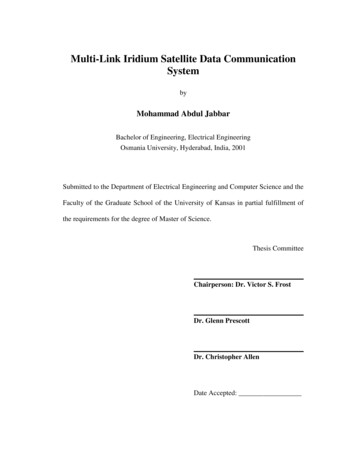
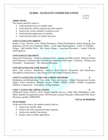
Introduction – Special Purpose Satellite Systems NASA satellites like ATS3, LES9,GOES,TDRS1,andMARISAT2provide broadband access to PolarRegions Geo-synchronous, they have a limitedvisibility window at Poles – typically10-13 hrs/day. High satellite altitude and low elevationangles (1-20) result in extremely largefield equipment. May not be readily available20 m diameter Marisat and GOES antenna at South PoleUniversity of Kansas6
Introduction – Problem Statement Problem StatementA reliable, lightweight, portable and easily scalable data/Internetaccess system providing true Polar coverage. SolutionImplement a multi-link point-to-point Iridium communication systemto combine multiple satellite links to obtain a single logical channelof aggregate bandwidth.University of Kansas7
Background - IridiumSatellite TypeLEOSatellite altitude780 kmMinimum elevation angle8.20Average satellite view time9-10 minutesAccess schemeFDMA and TDMAMaximum number of located users80 users in a radius of 318 kmTheoretical throughput2.4 – 3.45 KbpsType of data servicesIridium-to-Iridium, Iridium-to-PSTNUniversity of Kansas8
Background - Inverse Multiplexing Increases thesignificantlyavailablebandwidthperApp 2App 3MultiplexingapplicationMulti-link point-to-point protocol (MLPPP), an extensionto the PPP is a packet based inverse multiplexingsolutionOverhead of 12 bytesFragmentation of network layer protocol data units(PDU’s) into smaller segments depending upon the PDUsize, link MTUs and the number of available links.High Bandwidth LinkLow Bandwidth LinksApp 1Inv-Mux Inverse Multiplexing - Data from a single application isfragmented and or distributed over multiple lowbandwidth links.App 1Mux Traditional Multiplexing - Data from a multipleapplications/users sent over a single high bandwidth link.Inverse multiplexingUniversity of Kansas9
Multi-channel Iridium System – DesignThe design requirements of the system are as follows. The multi-channel implementation should maximize the throughput. To support real-time interactions, the system should minimize the end-to-end delay. The overall system should be reliable and have autonomous operation so as to handlecall drops and system/power failures in remote field deployment.University of Kansas10
Multi-channel Iridium System – Protocol StackRemote SystemLocal SystemApplicationApplicationHTTP, FTP, SSHHTTP, FTP, SSHTCPTCPIPIPPPP/MLPPPPhysical Modemspoint-to-point satellite linksPPP/MLPPPPhysical ModemsUniversity of Kansas11
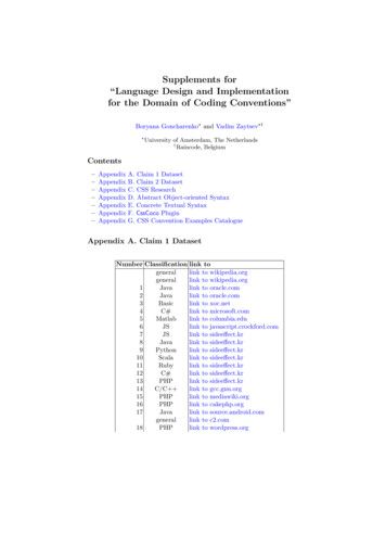
Multi-channel Iridium System – Network ArchitectureNGRIP Camp, GreenlandWorld Wide Web100 MbpsEthernet(Default gateway)(Default gateway)PPP ServerGuser 4PPP ClientITTC Default Routereth0User 2100 MbpsEthernetppp0P-T-P Satellite linketh0ppp0User 1Guser 3User 3CampWI-FIGuser 2G user 1ITTC Network, University of KansasUniversity of Kansas12
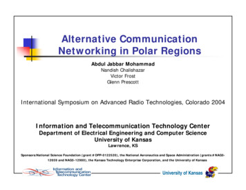
4-Channel Iridium System ImplementationI. Modem 1I. Modem 2I. Modem 3I. Modem 4AntennaGridPPP clientUSB-SERIALRemoteSystemIridiumGatewayRemote SubsystemPPP ServerMulti-portPCI cardLocalSystemModemPoolPSTNLocal SubsystemUniversity of Kansas13
4-Channel System – Implemented at KUUniversity of Kansas14
4-Channel System – Implemented at KUUniversity of Kansas15
4-Channel System – Software OverviewUser LevelUser Request/System bootConnectManagementSoftwareSelect the modem to bedialedPPP linkestablishedStart PPPDPPP clientSelect client parameters,chat scriptsNegotiate LinkParametersSerial connectionestablishedInvoke chat scriptChat ScriptsInitialize modem, requestbearer serviceCheck the baud rate,serial bitsAT commandsPhysicalModemsExecute commands dialnumberFailFailRingWait forresponseReceive the responsefrom the other endFailSoftware flow control at the PPP clientUniversity of Kansas16
4-Channel System – Software OverviewSoftware flow control at the PPP ServerUniversity of Kansas17
4-Channel System – Modem Flow ControlCheck if anymodem isaliveSTARTConnectModem nectModem 2FAILFAILConnectModem 3ConnectModem AILEDOKMonitorStatusUniversity of Kansas18
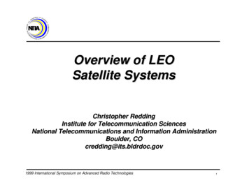
Field Tests and Results – Field implementationSystem withcontrol softwareUSB InUSB OutAntennaConnectorsDimensions: 24x19x5University of Kansas19
Field Tests and Results – Antenna Setup3 FT10 FTUniversity of Kansas20
Results – Delay and Loss Measurement Ping tests between the two machines at the end of the of satellite link One way propagation delay (800 8000 6000)Km / (3e6)Km/sec 49msec Transmission time for 64 bytes@2.4Kbps 64*8/2400 213msec Theoretically, the RTT delay 2*(49 213) 524msec delay at the gateway Test results show an average RTT delay of 1.8 sec, which may be attributed to the intersatellite switching and delay at the gatewayRTT (sec)Packets ity of Kansas21
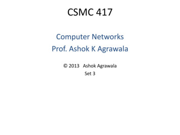
Results – Delay MeasurementRandom variation of delay High mean deviation Delay increases linearly withRTT Vs Time of the dayRTT in sec packet size Normalized delay is almost876543210MinAvgMax1:00constant for MTU sizes 8003:009:0013:0015:0020:00Time of the day in hh:mmbytesNormalized RTT Vs Packet SizeChanging distance between the35Normalized RTT (msec/byte) user and satellite as well asbetween satellites themselves(ISLs) Non-uniform traffic distribution,2532.0526.50201513.831012.359.2450 varying delays on different routes3056 100 2003005007.518007.5210007.0412007.131500Packet Size (Bytes)University of Kansas22
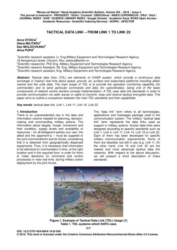
Results – Throughput Method1 Modem2 Modems3 Modems4 ModemsIperf2.14.07.09.6Iperf1.93.97.09.3Throughput varies to someIperf1.74.56.89.7extend due to RTT age2.14.256.889.26Tools used – TTCP, IPERFEfficiency 90%Effective throughputs during large file transfersUpload 62392752.34568151.52871432.5359524Throughput (K b p s)File Size (MB)Throughput Vs Number of Modems1098765432109.266.884.252.1123Number of modemsUniversity of Kansas423
0Time intervalbetween call ty of 2:0021:15modemsNumber of 122:3921:5721:15Call drop eventResults – Reliability: 10th July 24 hr testCall drop events vs. TimeTotal :13 Call dropsTimeModem up times during 24 hour testUptime %32180.691.894.796.813761824
Time intervalbetween call ty of r of online 18:1217:3316:5416:1515:3614:57Call drop eventResults – Reliability: 12th July 24 hr testCall drop events vs. TimeTotal :16 Call dropsTime4Modem up times during second 24 hour testUptime %321080929596Time738625
Results – TCP performance of a single link TCP Version – TCP SACK Throughput of a segment is defined as the sizeThroughput vs. Time-------- avg. of last 10 segments-------- avg. of all the segments upto that pointof the segment seen divided by the time sincethe last segment was seen (in this direction). RTT is defined as the time difference betweenthe instance a TCP segment is transmitted (bythe TCP layer) and the instance anacknowledgement of that segment is received. The average throughput of the connection isRTT vs. Time2.45Kbps. The average RTT was found to be 20 seconds Bandwidth Delay Product (BDP) 2400*20/8 6000 bytes 4 segments. Due to low throughput, the BDP is small.University of Kansas26
Results – TCP performance of a 4-channel system The average throughput obtained - 9.4 Kbps The average RTT observed - 16.6 seconds Factors affecting throughput and RTT TCP Slow start MLPPP fragmentation Random delay variation TCP cumulative acknowledgmentsTime Sequence GraphThroughput vs. Time-------- avg. of last 10 segments-------- avg. of all the segments upto that pointRTT vs. Time------- Received Acknowledgements------- TCP segments transmitted------- Received window advertisementUniversity of Kansas27
Results – TCP performance of a 4-channel systemTime Sequence Graph Outstanding Unacknowledgeddata and Congestion windowTime Sequence Graph------- Received Acknowledgements------- TCP segments transmitted------- Received window advertisementOutstanding Unacknowledged Data------- Instantaneous outstanding data samples------- Average outstanding data------- Weighted average of outstanding dataUniversity of Kansas28
Results – TCP performance degradation due to packet loss Low packet loss, long time experiments needed to determine the performance degradation Two packet losses were observed in the FTP video upload resulting in packetretransmissions Packet losses usually occur during call hand-offs Retransmission time outs (RTO) is very large due to high RTT and high mean deviationTime Sequence GraphTime Sequence GraphRetransmitted packetRetransmitted packetUniversity of Kansas29
Results – TCP performance degradation due to packet loss Effect on the TCP performance due to packetRTT vs. Timeloss Decrease in the throughput following the packetloss RTT peaks around the packet loss The average throughput of the connection isobserved to be 7.44 Kbps.Outstanding Unacknowledged DataThroughput vs. TimeUniversity of Kansas30
Results – TCP performance degradation due to call drop Packet loss due to a call drop on one links ofthe multilink bundleTime Sequence GraphA finite amount of time for the data link layerrealize the link has failedLarge RTO timerThe entire window of packets (12 in this case)and acknowledgements that are in flight onthat particular link are dropped.Throughput of the connection – 7.6 Kbps.------- Received Acknowledgements------- TCP segments transmitted------- Received window advertisementOutstanding Unacknowledged DataTime Sequence Graph------- Instantaneous outstanding data samples------- Average outstanding data------- Weighted average of outstanding dataUniversity of Kansas31
Results – Mobile testsTest LocationUniversity of Kansas32
Results – Mobile PerformanceSTARTThroughput vs. TimeSTOPAvg. Throughput 9 KbpsUniversity of Kansas33
Results – Mobile Performance(cont.d)STARTThroughput vs. TimeSTOPAvg. Throughput 9.34 KbpsUniversity of Kansas34
Results – ApplicationsSummer 2003 field experiments Software downloads – up to 7.2 Mbps Wireless Internet access Video conference - real time audio/video Video Uploads - Outreach General Camp useUniversity of Kansas35
Conclusions In order to provide data and Internet access to Polar Regions, we have developed areliable, easily scalable, lightweight, and readily available multi-channel datacommunication system based on Iridium satellites that provide round the clock, pole-topole coverage. A link management software is developed that ensures fully autonomous and reliableoperation An end-to-end network architecture providing Internet access to science expeditions inPolar Regions is demonstrated. This system provided for the first time, Internet access to NGRIP camp at Greenland andobtained the call drop pattern. The TCP performance and the reliability of the system is characterizedUniversity of Kansas36
Future Work Modify the MLPPP code so that the interface is attached to the bundle and not to theprimary link Additional research to determine the cause of delay and develop methods toovercome it. Evaluate the new data-after-voice (DAV) service from IridiumEvaluate different versions of TCP to determine the enhancements that can handlethe random variation and value of RTT Improve the user friendliness of the system GUI for connection setup Self-test / diagnostic tools for troubleshootingResearch into the spacing and sharing of antennas to reduce the antenna footprintUniversity of Kansas37
PublicationsConference Publications Iridium-Based Data Communication System Providing Internet Access to Polar Expeditions, AMohammad, V Frost, D Braaten, Poster, AGU conference, San Francisco, December 2003. Alternative Communication Networking in Polar Regions, Abdul Jabbar Mohammad, NandishChalishazar, Victor Frost, Glenn Prescott, ISART conference, Colorado, March 2004Journal Publications Data communication in Polar Regions using Iridium/Wi-Fi Integrated System, Abdul JabbarMohammad, Nandish Chalishazar, Victor Frost, Glenn Prescott, and David Braaten,to be submitted to Journal of GlaciologyRelated Projects Development of Multilink PPP Technologies from Iridium, Sponsored by HarrisCorporation, PI - Dr. Victor FrostUniversity of Kansas38
Questions ? Comments ?University of Kansas39
Background - Iridium Type of data services Iridium-to-Iridium, Iridium-to-PSTN Theoretical throughput 2.4 - 3.45 Kbps Maximum number of located users 80 users in a radius of 318 km Access scheme FDMA and TDMA Average satellite view time 9-10 minutes Minimum elevation angle 8.20 Satellite altitude 780 km Satellite Type LEO