Transcription
DRAFTING STANDARDS FORWATER/WASTEWATERPIPELINE PROJECTSOctober, 2011
TABLE OF CONTENTSPREFACEP.1BACKGROUND .P-1P.2ABBREVIATIONS .P-2CHAPTER 1 GENERAL REQUIREMENTS1.1INTRODUCTION .1-11.2SOFTWARE APPLICATION .1-11.3DATA COLLECTION AND DRAWING CHECKLIST .1-11.4FILE MANAGEMENT .1-2CHAPTER 2 DRAFTING CONVENTIONS2.1GENERAL. . .2-12.2DRAFTING BASE POINTS .2-12.3MASTER MODEL SHEET MODEL .2-12.4REFERENCES .2-12.5TEXT FONT AND ORIENTATIONS.2-22.6ANNOTATIONS .2-32.7EXISTING, PROPOSED AND FUTURE FEATURES .2-32.8DRAWING ORIENTATION.2-42.9STATIONS . .2-42.10COORDINATES . .2-52.11CROSS AND PARALLEL UNDERGROUND UTILITIES .2-52.12SLOPE .2-62.13ELEVATIONS . .2-62.14FLOWLINES/INVERT ELEVATIONS . .2-62.15DRAWING SCALES .2-72.16MATCH MARKS .2-7DWU PIPELINE DRAFTING STANDARDSTOC-1OCTOBER 2011
CHAPTER 3 DRAWING CONFIGURATION3.1GENERAL . .3-13.2PLAN AND PROFILE CONFIGURATION .3-13.3COVER SHEET .3-23.4GENERAL NOTES . .3-43.5STANDARD DESIGN SHEET . . .3-43.6STANDARD CALLOUTS .3-11CHAPTER 4 WORKING UNITS, COLOR, STYLE AND WEIGHT4.1GENERAL . .4-14.2WORKING UNITS .4-14.3GLOBAL ORIGIN .4-24.4COLOR . .4-24.5LINE STYLE .4-24.6LINE WEIGHT . .4-3CHAPTER 5 LEVEL MANAGEMENT5.1GENERAL . .5-15.2LEVEL NAMING CONVENTION .5-15.3STANDARD LEVEL CATEGORIES .5-25.4PREDEFINED LEVELS.5-2DWU PIPELINE DRAFTING STANDARDSTOC-2OCTOBER 2011
CHAPTER 6 DRAFTING RESOURCE LIBRARIES6.1GENERAL .6-16.2PREDEFINED FILES .6-16.3SEED FILE .6-26.4LEVEL LIBRARY .6-26.5CELL LIBRARY .6-26.6TEXT STYLE RESOURCE LIBRARY .6-26.7MISCELLANEOUS DRAWING FEATURES .6-36.8REFERENCE SCHEMATICS .6-3CHAPTER 7 PLOT CONFIGURATION6.1GENERAL .7-16.2ATTRIBUTE DEFINITIONS .7-1DWU PIPELINE DRAFTING STANDARDSTOC-3OCTOBER 2011
LIST OF TABLESTABLE 1.4.1FILE NAMING CONVENTIONTABLE 3.6.1WATER/WASTEWATER TITLE CALLOUTSTABLE 3.6.2TYPICAL WATER MAIN CALLOUTSTABLE 3.6.3TYPICAL WASTEWATER MAIN CALLOUTSTABLE 4.2WORKING UNITSTABLE 4.4LIST OF COLORSTABLE 4.5LIST OF LINE STYLESTABLE 4.2LIST OF LINE WEIGHTSTABLE 5.3LIST OF STANDARD LEVELS CATEGORIESTABLE 5.4LIST OF PREDEFINED LEVELSTABLE 6.2:LIST OF PREDEFINED FILESDWU PIPELINE DRAFTING STANDARDSTOC-4OCTOBER 2011
LIST OF FIGURESFIGURE 1.4.2SEQUENCE OF FILINGFIGURE 2.5TEXT AND FONT ORIENTATION CONVENTIONSFIGURE 2.8DRAWING ORIENTATION CONVENTIONSFIGURE 2.8DRAWING ORIENTATION CONVENTIONSFIGURE 2.10STATIONING CONVENTION AND CROSS-REFERENCINGFIGURE 2.14FLOWLINE CONFIGURATIONS AT WASTEWATER MANHOLEFIGURE 2.16.1TYPICAL MATCH MARKS FOR A SINGLE UTILITY PROJECTFIGURE 2.16.2TYPICAL MATCH MARKS FOR A COMBINED UTILITY PROJECTFIGURE 2.16.1TYPICAL MATCH MARKS FOR A VERTICAL SHIFTFIGURE 3.3.1TYPICAL COVER SHEET A MAJOR UTILITY PROJECTFIGURE 3.3.2TYPICAL COVER SHEET A MULTIPLE LOCATIONS PROJECTFIGURE 3.4TYPICAL GENERAL NOTE SHEETFIGURE 3.5STANDARD DESIGN SHEETFIGURE 3.5.1STANDARD DESIGN SHEET BORDERFIGURE 3.5.2STANDARD TITLE BLOCKFIGURE 3.5.5.1P.E. DISCLAIMER FOR PRELIMINARY PLANSFIGURE 3.5.5.3DISCLAIMER FOR RECORD DRAWINGFIGURE 4.4STANDARD COLOR, STYLE AND WEIGHT DESIGNATIONSFIGURE 6.4A:CELL LIBRARY- GENERALFIGURE 6.4B:CELL LIBRARY- WATER AND WASTEWATERDWU PIPELINE DRAFTING STANDARDSTOC-5OCTOBER 2011
LIST OF EXHIBITSEXHIBIT A.1SYMBOLS: GENERALEXHIBIT A.2SYMBOLS: TOPOGRAPHIC FEATURESEXHIBIT A.3SYMBOLS: PAVINGEXHIBIT A.4SYMBOLS: STORM DRAINSEXHIBIT A.5SYMBOLS: UTILITIESEXHIBIT A.6SYMBOLS: WATER APPURTENANCESEXHIBIT B.1NORTH ARROW, ARROWHEAD, DIMENSIONS AND LEADER LINESEXHIBIT C.1TEXT STYLE: STANDARD TITLE BLOCKEXHIBIT C.2TEXT STYLE: STANDARD DESIGN SHEET MISC. ITEMSEXHIBIT C.3TEXT STYLE: GENERAL PLAN VIEWEXHIBIT C.4TEXT STYLE: PROPERTY PLAN VIEWEXHIBIT C.5TEXT STYLE: WATER/WASTEWATER PLAN VIEWEXHIBIT D.1PLAN VIEW: EXISTING & PROP. PROPERTY LINESEXHIBIT D.2PLAN VIEW: EXISTING PAVEMENT & STORM DRAINSEXHIBIT D.3PLAN VIEW: PROPOSED PAVEMENT & STORM DRAINSEXHIBIT D.4PLAN VIEW: EXISTING UTILITIES & APPURTENANCESEXHIBIT E.1PLAN VIEW: EXISTING WATER MAINSEXHIBIT E.2PLAN VIEW: PROPOSED WATER MAINSEXHIBIT E.3PLAN VIEW: EXISTING WATER APPURTENANCESEXHIBIT E.4PLAN VIEW: PROPOSED WATER APPURTENANCESEXHIBIT F.1PLAN VIEW: EXISTING WASTEWATER MAINSEXHIBIT F.2PLAN VIEW: PROPOSED WASTEWATER MAINSEXHIBIT F.3PLAN VIEW: EXISTING WASTEWATER APPURTENANCESEXHIBIT F.4PLAN VIEW: PROPOSED WASTEWATER APPURTENANCESDWU PIPELINE DRAFTING STANDARDSTOC-7OCTOBER 2011
EXHIBIT G.1TEXT STYLE: GENERAL PROFILE VIEWEXHIBIT G.2TEXT STYLE: EXISTING/PROP. WATER/WASTEWATER PROFILE VIEWEXHIBIT H.1PROFILE VIEW: EXISTING UTILITIES AND APPURTENANCESEXHIBIT H.2PROFILE VIEW: PROPOSED UTILITIES AND APPURTENANCESEXHIBIT I.1PROFILE VIEW: EXISTING WATER MAINSEXHIBIT I.2PROFILE VIEW: PROPOSED WATER MAINSEXHIBIT I.3PROFILE VIEW: EXISTING WATER APPURTENANCESEXHIBIT I.4PROFILE VIEW: PROPOSED WATER APPURTENANCESEXHIBIT I.5PROFILE VIEW: VERTICAL CURVES EXISTING AND PROPOSED WATERMAINSEXHIBIT J.1PROFILE VIEW: EXISTING WASTEWATER MAINS AND APPURTENANCESEXHIBIT J.2PROFILE VIEW: PROPOSED WASTEWATER MAINS AND APPURTENANCESEXHIBIT J.3PROFILE VIEW: VERTICAL CURVES EXISTING AND PROPOSEDWASTEWATER MAINSEXHIBIT K.1EXAMPLE PLAN VIEW: WATER/WASTEWATER MAINS WITHIN STREETRIGHT-OF-WAYEXHIBIT K.2EXAMPLE PROFILE VIEW: WATER MAIN WITHIN STREET RIGHT-OF-WAYEXHIBIT K.3EXAMPLE PROFILE VIEW: WASTEWATER MAIN WITHIN STREET RIGHT-OFWAYEXHIBIT K.4EXAMPLE PLAN VIEW: WASTEWATER MAIN WITHIN CREEK/EASEMENTEXHIBIT K.5EXAMPLE PROFILE VIEW: WASTEWATER MAIN WITHIN CREEKEXHIBIT K-6EXAMPLE PLAN VIEW: EXIST./PROP. PAVEMENT AND STORM DRAINSEXHIBIT K.7EXAMPLE POSTING 1: POSTING EASEMENTS ON DRAWINGEXHIBIT K. 8EXAMPLE POSTING 2: VARIOUS TYPES OF EASEMENTSEXHIBIT K. 9EXAMPLE POSTING 3: POSTING OF APPROVALS, AGREEMENTS & RELEASESDWU PIPELINE DRAFTING STANDARDSTOC-7OCTOBER 2011
LIST OF APPENDICESAPPENDIX A.1SURVEY CHECKLISTAPPENDIX A.2BASEMAP CHECKLISTAPPENDIX A.3DESIGN CHECKLISTAPPENDIX A.4AS-BUILT DRAWING CHECKLISTAPPENDIX A.5RECORD DRAWING CHECKLISTAPPENDIX B.100PREDEFINED LEVELS: CIVIL- WATER (C WATER)APPENDIX B.200PREDEFINED LEVELS: CIVIL- WASTEWATER (C WASTEWATER)APPENDIX B.300PREDEFINED LEVELS: CIVIL- TRAFFIC (C TRAFFIC)APPENDIX B.400PREDEFINED LEVELS: CIVIL- PAVING (C PAVING)APPENDIX B.500PREDEFINED LEVELS: CIVIL- STORM (C STORM)APPENDIX B.1000 PREDEFINED LEVELS: SURVEY- PROPERTY (C PROPERTY)APPENDIX B.2000 PREDEFINED LEVELS: SURVEY- PAVEMENT (V PVMT)APPENDIX B.3000 PREDEFINED LEVELS: SURVEY- RAIL (V RAIL), BUILDING (V BLDG),CONTROL (V CTRL), TOPOGRAPHY (V TOPO), TRAFFIC (V TRAF)APPENDIX B.4000 PREDEFINED LEVELS: SURVEY- WATER (V WATER)APPENDIX B.5000 PREDEFINED LEVELS: SURVEY- WASTEWATER (V WW)APPENDIX B.6000 PREDEFINED LEVELS: SURVEY- STORM (V STRM), UTILITY (V UTILITY)APPENDIX B.7000 PREDEFINED LEVELS: SURVEY- DESIGN (V DESIGN)APPENDIX B.8000 PREDEFINED LEVELS: SURVEY- TRAINGULATION, (V TRIANGULATION,V DTM, V CONTOUR)DWU PIPELINE DRAFTING STANDARDSP-1OCTOBER 2011
PREFACEP.1BACKGROUNDThe intent of this manual is to provide a consistent graphic management guideline fordesign and drafting of all water and wastewater main projects owned and operated byDallas Water Utilities (DWU). This manual replaces the second edition of “DraftingStandards for Pipeline Projects” by DWU dated January, 1998. The chronological listof events in developing this manual is summarized as follows:Compilation of drafting instructions into first editionof the manual.JAN, 1988FIRST EDITION:JAN, 1998SECOND EDITION: Revision of the 1988 manual to include standard planformat, computer aided drafting and design (CADD)settings and sample drawings.OCT, 2010 THIRD EDITION:Revision of the 1998 manual to incorporate updatedgeneral requirements, drafting conventions, drawingconfigurations, CADD settings and custom seed filewith predefined levels, text style, cell library andother features.OCT, 2011:Revision of the 2010 manual to correct minor errorsin the text, add illustrations, update the cell libraryand revise the level library so the colors forunderground utilities correspond with the AmericanPublic Works Association Uniform Color Code forMarking Underground Utility Lines.This October 2011 of “Drafting Standards for Water/Wastewater Pipeline Projects” iswritten by Engineering Services, Dallas Water Utilities. Any questions or suggestionsregarding to this manual should be forwarded to Engineering Services, Dallas WaterUtilities.DWU PIPELINE DRAFTING STANDARDSP-2OCTOBER 2011
P.2ABBREVIATIONSACAsbestos CementCATVCable TVANSIAmerican National StandardsCAVCombination Air ValveInstituteCBConstruction BookARVAir Release ValveC/CCenter to CenterASPHAsphaltCICast IronASTMAmerican Society for TestingCIPPCured-in-Place PipeMaterialsC/LCenter Line or ClassAVAir ValveCOCleanoutAVVAir/Vacuum ValveCODCity of DallasAWWAAmerican Water WorksCONCConcreteAssociationCONNConnectionBBFBell X Bell X FlangeCONSTConstructionBCBack of CurbCONTContractBFPBackflow PreventerCPControl PointBFVButterfly ValveCTSCorrosion Test StationBHBud Holcomb or Bore HoleD or DIADiameterBKBackwardDARTDallas Area Rapid TransitBLDGBuildingDIDuctile IronBLKBlockDRDimension RatioBLVDBoulevardDTMDigital Terrain ModelBMBench MarkDWGDrawingBOPBottom of PipeDWUDallas Water UtilitiesBOTOCBy Other Than Open CutEEastBOVBlowoff ValveECIEnamel Lined Cast IronBTWNBetweenEL or ELEV ElevationCADComputer Aided DraftingEL UNKElevation UnknownCADDComputer Aided Drafting ateCALCDWU PIPELINE DRAFTING STANDARDSP-3OCTOBER 2011
ETJExtra Territorial JurisdictionIRIron RodEWEach WayLBLedger BookEXExistingLFLinear FeetF or FLGFlangeLLLiquid LimitFBField BookLNLaneFFFinish FloorLTLeftFHFire HydrantMBMail BoxFLFlow LineMJMechanical JointFMFarm-to-Market (Road)MHManholeFOFiber OpticMSLMean Sea LevelFORFFlange Outlet Reducing FlangeNNorthFTFeetNA or N/ANot ApplicableFWYFreewayNAD83North American Datum of 1983FWDForwardNTSNot to ScaleGGASODOutside DiameterGISGeographic Information SystemOEOverhead ElectricGMGas MeterPPetroleumGPSGlobal Positioning SystemPACPPipeline Assessment andGVGate ValveCertification ProgramH or HORZ HorizontalPCPoint of CurvatureHBHorizontal BendPCCPPre-Stressed Concrete CylinderHDDHorizontal Directional DrillingHDPEHigh Density PolyethylenePGPageHOEHome Owner’s ExtensionPEPlain End or Professional EngineerHWYHighwayPIPlasticity Index or Point ofIDInside DiameterIHInterstate HighwayPIDProject Identification NumberI/IInflow/InfiltrationP/LProperty LineINInchPOPitot OutletINVInvertPPPower PoleIPIron PinPRPressureDWU PIPELINE DRAFTING STANDARDSPipeIntersectionP-4OCTOBER 2011
PROPProposedSTDStandardPRVPressure Reducing ValveS/WSide WalkPSIPounds Per Square InchSW3PStorm Water Pollution PreventionPTPoint of TangentPVIPoint of Vertical IntersectionSUESubsurface Utility EngineeringPVCPolyvinyl ChlorideTTelephonePVMTPavementTOPTop of PipePW&TPublic Works & TransportationTHTest HoleQLQuality LevelTINTriangulated Irregular NetworkQTYQuantityTACTexas Administrative CodeRCCPReinforced Concrete CylinderTBMTemporary Bench MarkPipeTCEQTexas Commission onPlanRCPReinforced Concrete PipeRDRoadTORFThreaded Outlet Reducing FlangeROWRight of WayTXDOTTexas Department ofRPMPReinforced Polymer Mortar PipeRRRail RoadUEUnderground ElectricRTRightUGUndergroundRTRPReinforced Thermosetting ResinV or VERTVerticalPipeVBVertical BendNorth Central Texas Council ofVCPVitrified Clay PipeGovernmentsVCTVitrified Clay TileSDStorm DrainVOLVolumeSDRStandard Dimension RatioWWater or WestSSouthWDBMWater Department Bench MarkSHState Highway or SheetWWWastewaterS/LSurvey LineW/WWWater/WastewaterSTStreetWWADWastewater Access DeviceSTAStationWTPWater Treatment PlantSTA. EQ.Station EquationWWTPWastewater Treatment PlantNCTCOGDWU PIPELINE DRAFTING STANDARDSEnvironmental QualityTransportationP-5OCTOBER 2011
CHAPTER 1GENERAL REQUIREMENTS1.1INTRODUCTIONThis chapter outlines the general drafting standards to be adopted in all water andwastewater pipeline design projects for Dallas Water Utilities (DWU).1.2SOFTWARE APPLICATIONMicroStation V8 XM or the latest edition shall be used for design and drafting of allDWU water and wastewater main projects. All drawings used by or provided to DWUshall be in “dgn” format. In addition, the latest version of InRoads or equivalentsoftware(s) as approved by DWU, shall be used to perform survey data import, surfacemodeling, horizontal and vertical alignment, and other related tasks for water andwastewater main design.1.3DATA COLLECTION AND DRAWING CHECKLISTAll survey for design and subsequent various forms of drawings shall be prepared inaccordance with DWU standards as specified in this section.1.3.1SURVEYSurvey shall be conducted prior to initiation of any detailed design. The majority of theexisting topographic features shall be obtained from the survey. Existing and proposedutility information shall initially be obtained from the utility records supplied by eachutility company. In addition, the location of existing utilities shall be confirmed bysurvey or field investigation as necessary.A general checklist for water andwastewater main survey is included under APPENDIX A.1.1.3.2BASEMAPA basemap shall be prepared to create a design basis for water and wastewater mainprojects. A general checklist for water and wastewater main basemap is included underAPPENDIX A.2.DWU PIPELINE DRAFTING STANDARDS1-1OCTOBER 2011
1.3.3DESIGN PLANAll water and wastewater pipeline drawings shall be prepared in accordance with theDWU Water and Wastewater Pipeline Design Manual, Latest Edition.A typicalchecklist for water and wastewater main design plans is included under APPENDIX A.3.1.3.4AS-BUILT DRAWINGAs-built drawings shall consist of handwritten notes demonstrating any field changesduring construction.A general checklist for water and wastewater main as-builtdrawings is included under APPENDIX A.4.1.3.5RECORD DRAWINGRecord drawings shall be prepared by the designer showing any field changes asmarked on the as-built drawings. A typical checklist for water and wastewater mainrecord drawings is included under APPENDIX A.5.1.4FILE MANAGEMENTAll MicroStation files associated with water and wastewater design shall be properlynamed as described in this section.1.4.1NAMING CONVENTIONSA typical water and wastewater drawing file shall be named as follows:“Drawing Type-Project Identifier.File Extension”Where, “Drawing Type” shall include abbreviation for DWU 3D Seed File(DWUSeed3D), DWU 2D Seed File (DWUSeed2D), 3D Base Map (Basemap3D), 2DBase Map (Basemap2D), Cover Sheet (C), General Sheet (G), Design Sheet (D),Traffic Control Sheet (T), or other relevant drawings. “Project Identifier” includesproject identification (PID) number, construction contract (CONT) number, streetname, project area name, or unique DWU Water/Wastewater file number. In addition,“File Extension” typically denotes to “DGN” for all MicroStation drawings.DWU PIPELINE DRAFTING STANDARDS1-2OCTOBER 2011
Accordingly, a preferred naming convention for drawing files is shown in Table 1.4:TABLE 1.4: FILE NAMING CONVENTIONFile TypeDWU 3D Seed File(Read Only)File NameDWUSeed3D-xx.dgnNote“xx” refers to date created or revised:DWUSeed3D-Sept2010DWU 2D Seed File(Read Only)DWUSeed2D-xx.dgn“xx” refers to date created or revised:DWUSeed2D-Sept20103D BasemapBasemap3D-xx.dgn“xx” refers to project identification number(PID), street or project area name:Basemap3D-PID763 MainSt.dgnBasemap3D-PID764 ParkMainAlley.dgn2D BasemapBasemap2D-xx.dgn“xx” refers to project identification number(PID), street or project area:B2D-PID763 MainSt.dgnB2D-PID764 ParkMainAlley.dgnCover SheetC-xx.dgnGeneral Sheet(General Note,Survey ControlSheet etc.)G-xx.dgnDesign Sheet(Plan, Profile, orMiscellaneousDetails)Traffic ControlSheetD-xx.dgn“xx” refers to construction contract or filesheet number* as assigned:C-CONT05633 634F.dgnC-411Q1023 Sh001.dgnC-685W0116 Sh013.dgn“xx” refers to construction contract or, filesheet number* as assigned:G-CONT05633 634F.dgnG-411Q0012 Sh112.dgnG-685W0016 Sh013.dgn“xx” refers to unique file number*:D-411Q0002 Sh001.dgnD-685W0016 Sh013.dgnT-xx.dgn“xx” refers to unique file number*:T-411Q0009 Sh006.dgnT-685W1016 Sh112.dgn*Note: All file and sheet numbers shall consist of 4 and 3 digits, respectively, to allow proper sorting and to be compatibleDWU vault numbering system ( Example: 411Q0001 and Sh001)DWU PIPELINE DRAFTING STANDARDS1-3OCTOBER 2011
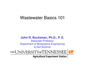
1.4.2SEQUENCE OF FILINGThe preliminary base map as submitted by the surveyor must be based on DWU 3Dseed file entitled “DWUSeed3D-xx.dgn” and shall be saved as a 3D base map file“Basemap3D-xx.dgn”.This file shall consist of the survey data along withtriangulation, break lines, contours, pavements, and other required drafting by thesurveyor(s) as necessary.The 3D base file “Basemap3D-xx.dgn” as obtained from the surveyor may be furtherreferenced to a 2D base file as “Basemap2D-xx.dgn” by the designer prior to detaileddesign. All final design sheets shall be saved as individual files and to be named as “Cxx.dgn”, “G-xx.dgn” or “D-xx.dgn” for cover, general or design sheets, respectively, asnecessary. In addition, all final design sheets shall be stand alone drawings without anyreferences or attachment. A typical sequence of filing naming is shown in Figure1.4.2:DWU Seed3D-xx.dgn(DWU)DWU igner)D-xx.dgn(Designer)T-xx.dgn(Designer)FIGURE 1.4.2: SEQUENCE OF FILINGDWU PIPELINE DRAFTING STANDARDS1-4OCTOBER 2011
CHAPTER 2DRAFTING CONVENTIONS2.1GENERALThis Chapter describes basic drafting conventions to be used for water and wastewatermain projects.2.2DRAFTING BASE POINTSAll DWU projects shall use City of Dallas Benchmarks for vertical control. The list ofCity of Dallas Benchmarks is available at the City of Dallas Website. In addition, allsurvey coordinates shall be tied to State Plane Coordinates, North Central Zone, NorthAmerican Datum of 1983 (NAD83). This will facilitate use of various design elementsinto the City of Dallas Geographical Information System (GIS) system.The coordinate system used for design shall match that used by the surveyor for datacollection and these coordinates shall not be rotated or translated. MicroStation X, Ybase point of 0, 0 should match a Northing, Easting of 0, 0.2.3MASTER MODEL AND SHEET MODELAll drafting shall be done at 1:1, in engineering units, in the MicroStation “mastermodel” environment. The design along with standard border shall be referenced in a“sheet model” prior to plotting using appropriate scale factor, as necessary.2.4REFERENCESReferences shall be used wherever a part of the basemap or other information will beused in more than one drawing, so that any changes are automatically updated in all ofthe associated drawings. However, upon completion of final design, each design sheetshall be a stand alone drawing without any references or attachments and shall benamed as per Table 1.4. This will provide assured future retrieval of all informationthat is contained on the engineer’s sealed hard copy.DWU PIPELINE DRAFTING STANDARDS2-2OCTOBER 2011
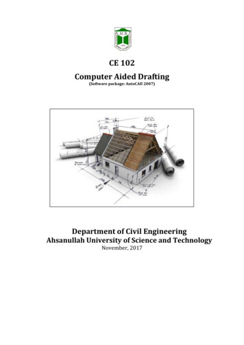
2.5TEXT FONT AND ORIENTATIONSThe standard text font for water and wastewater design plans shall be MicroStationText Font 23. This style of lettering has been the standard for the civil engineeringfield and produces a neat and legible text. This can also be accomplished quickly byfree hand using inclined Gothic lettering templates, if necessary.The orientation of design plans requires the placement of call out notes at variousangles skewed to the horizontal position. The standard text or lettering orientation shallbe as per Figure 2.5.FIGURE 2.5: TEXT FONT AND ORIENTATION CONVENTIONSDWU PIPELINE DRAFTING STANDARDS2-2OCTOBER 2011
2.6ANNOTATIONSUnusually large text shall not be used, except decorative fonts on cover sheet.Annotation associated with any feature shall be at line style 0 (solid) and weight of 0.Center left justification shall be used for blocks of text.In addition, followingguideline shall be used for annotations associated with features: Move annotation away from feature Line up annotation if possible Avoid odd abbreviations and squeezing text to fit Break leader lines at conflicts only Multiple leader lines may not intersect Group leader lines at about the same angle for neatnessEXISTING, PROPOSED AND FUTURE FEATURES2.7All existing, proposed or future features shall be clearly distinguishable from eachother. Following guidelines shall be used except otherwise predefined by DWU:2.7.1Existing Features:All the existing features shall be depicted with relatively thinner lines than proposed orfuture features of the same type. Grey scales are generally not allowed because of theirtendency to be lost during typical reproduction or photocopying processes.2.7.2Proposed Features:All proposed features shall be more prominently depicted than existing features for thesame type.2.7.3Future Features:All future features shall be more prominently depicted than existing features for thesame type. Typically, future features shall be at line style of 5 (short dash) andminimum weight of 2 (0.024 in) unless otherwise predefined by DWU.DWU PIPELINE DRAFTING STANDARDS2-3OCTOBER 2011
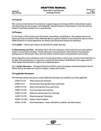
2.8DRAWING ORIENTATIONSThe orientation of the plan view should allow the placement of the design lengthwisealong the plan sheet while orientating north generally towards the top or right side ofthe sheet (FIGURE 2.8).Option 1: North towards TopOption 2: North towards RightFIGURE 2.8: DRAWING ORIENTATION CONVENTIONS2.9STATIONSAll water and wastewater pipeline stations shall be to the tenth of a foot(Ex. STA. 1 90.5). The pipeline alignment shall be developed with a continuous onehundred foot stationing format. This station format provides the means of referencingpertinent points of construction and proposed appurtenances along with providing areference between the plan and profile views. Typically, projects will begin with a zerostation point (0 00.0) and then proceed to the project ending point.The beginning station (0 00.0) for proposed wastewater mains shall be at the downstream connection point typically a manhole, and then proceed up stream. When notdictated by a down stream connection point, stationing should begin from west to east,or south to north. The west to east and south to north stationing configuration typicallyprovides left to right reading of plans with north directed to the top or to the right. Atypical stationing for water and wastewater project is shown under Figure 2.9.DWU PIPELINE DRAFTING STANDARDS2-4OCTOBER 2011
FIGURE 2.9: STATIONING CONVENTION AND CROSS-REFERENCING2.10COORDINATES:Texas State Plane Coordinates (Northing and Easting) shall be shown at beginning,ending, points of intersection (PI), points of curvature (PC), points of tangency (PT)and other station points of major appurtenances (manhole, cleanout, wastewater accessdevice). The station 0 00.0 may also be tied to the survey control points, as necessary.Ties to easily locatable objects such as valve caps or manhole covers may be used tolocate the station 0 00.0.2.11CROSS AND PARALLEL UNDERGROUND UTILITIESAll underground cross utilities shall be shown in the profile with elevations asavailable. All parallel underground utilities within minimum 10 feet are to be shownin the profile.DWU PIPELINE DRAFTING STANDARDS2-5OCTOBER 2011
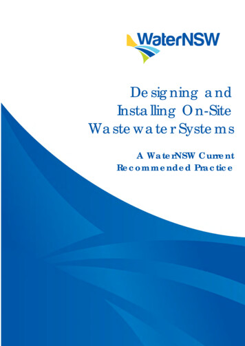
2.12SLOPEDesign slopes for all water and wastewater shall be nearest hundredth of a percent(Example: Slope 5.20%). All proposed mains shall include the proposed slope and allexisting mains shall include the existing slope, if it is thenearesthundredthofafoot(Example: El. 495.95)2.14FLOWLINES/ INVERT ELEVATIONSAll water and wastewater flowlines shall be to the nearest hundredth of a foot(Example: FL 495.95). All existing wastewater mains shall be shown with hatching inthe profile view as shown in FIGURE 2.14. Typically, left and top flowlines in the planview shall be placed at the left side of the manhole in the profile view. Similarly, rightand bottom flowlines are to be placed at the right side of the manhole in the profileview.FIGURE 2.14: FLOWLINE CONFIGURATIONS AT WASTEWATER MANHOLEDWU PIPELINE DRAFTING STANDARDS2-6OCTOBER 2011
2.15DRAWING SCALESCAD drawings shall be developed at a 1:1 ratio and then plotted to the following scaleunless otherwise approved by DWU.2.15.1Horizontal Scale:All plans shall be plotted at a horizontal scale of 1” 20’ to show sufficient plan detailsfor congested project locations such as alleys, easements, or street right-of-ways withnumerous underground facilities.Generally, 1” 20’ scale is most preferable;however, 1” 40’ may also be used for projects where the utilities are less congested.2.15.2Vertical Scale:All profiles are to be plotted on the vertical scale of 1" 6' with major horizontal linesat five (5) foot intervals and to the same horizontal scale as the plan view.2.15.3Variance:Special details, such as structures, may require the use of a scale which can providegreater detail than those available on the standard civil engineer scale. For theseinstances, the use of an appropriate architectural scale which provides greater detail isacceptable.2.16MATCH MARKSWhen a design spans more than one plan sheet, a design match mark must beestablished to reference the continuation of the design from one sheet to another. Thefollowing guidelines should be followed when establishing the location of matchmarks: Match Marks are to be placed at half or full station points (e.g. 10 00.0 or10 50.0). A quarter and three-quarter station points (e.g. 10 25.0 or 10 75.0) mayalso be acceptable, if necessary. Match Marks are to be perpendicular to the design alignment at the stationreferenced as the match mark point.DWU PIPELINE DRAFTING STANDARDS2-7OCTOBER
design and drafting of all water and wastewater main projects owned and operated by Dallas Water Utilities (DWU). This manual replaces the second edition of “Drafting Standards for Pipeline Projects” by DWU dated January, 1998. The chronological list of e