Transcription
DROPLET-BASED MICROFLUIDIC PLATFORMS FOR HIGH-THROUGHPUTDNA GENOTYPING AND AMPLIFICATIONbyTony J. ZhengA thesis submitted to Johns Hopkins University in conformity with the requirements for thedegree of Masters of Science and Engineering in Biomedical EngineeringBaltimore, MarylandAugust 2017
ABSTRACTCommon genetic analysis instruments in genotyping, allele discrimination, and PCRare standardized, indispensable tools in biological, medical, and science research laboratoriesand R&D industry sectors across the world. Constantly working to improve and create newapplications, many fields are looking to construct next-generation technologies that can offerhigher throughput, higher efficiency, and lower costs in such genetic analysis techniques. Inparticular, multinational agricultural companies, in the face of a rapidly growing humanpopulation, are working to improve crop production and to accelerate plant breeding andgenetic selection techniques in order to maintain global food supplies. These companies, suchas DuPont Pioneer we are in collaboration with, are now turning to new microfluidictechnologies that present a promising route for miniaturizing and up scaling high-throughputgenotyping. Microfluidic technologies reduce sample consumption by thousands, up tomillions fold from milliliter volumes to nanoliter droplets, lift processing constraints fromdiscrete 96-well plates to an unlimited, continuous-flow of droplet processing, and downsizeof physical footprint from bulky, benchtop instruments to palm-sized, miniaturized devices.Here, we present two novel microfluidic platforms: 1) a microfluidic platform formultiplexed genotyping of single nucleotide polymorphisms (SNPs), screening a series ofDNA targets against a library of probes, achieving 100% accuracy in SNP calling of syntheticmaize DNA targets and 93% accuracy in SNP calling of genomic maize DNA targets, using anInvader assay, and 2) a microfluidic platform for integrated, continuous-flow, droplet Taqmanbased PCR and end-point allele discrimination. The development of both microfluidic devicesoffers promising platforms for next generation, high throughput genotyping technologies.Thesis Readers: Jeff Wang, Ph.D., Dr. Eileen Haase, Ph.D., Dr. Vikram Chib, Ph.D.ii
ACKNOWLEDGEMENTSI would like to express my deepest appreciation and gratitude to my thesis advisor andprofessor, Dr. Jeff Wang and to my tremendous and invaluable mentors, Dr. Wen Hsieh, Dr.Helena Zec, and Dr. Divya Nalayanda, for their continuous teachings, mentorship, patience,and guidance throughout my research projects and experiences. I would also like to thank AnuKaushik, Dr. Frank Hsieh, and Brant Axt, for their Pioneer research project collaborations,teamwork, and discussions, and the rest of Dr. Wang’s lab for their supportive advice, feedback,and insights. Lastly, I would like to thank my family and friends for their constant love andsupport throughout my Masters program.iii
TABLE OF CONTENTSAbstract . iiAcknowledgements . iiiTable of Contents . ivList of Figures . viCHAPTER 1 – Continuous-Flow, Droplet-Based PCR . 11.1 Introduction . 11.2 Materials and Methods . 21.2.1 Multiplexed PCR.21.2.2 Invader Assay and Single Nucleotide Polymorphisms Detection.31.2.3 Device Design .41.2.4 Device Fabrication.61.2.5 Device Priming, Hydrophobic Surface Treatment.61.2.6 Optimization of Carrier Oil, Additives, and Surfactants.71.2.7 Device Operation.71.2.8 Fluorescence Detection and Data Analysis.91.3 Results and Discussion.111.3.1 Sample Loading via Nano Sample Processors.111.3.2 Benchtop Verification of Invader Assay.141.3.3 Fluorescence Detection of Invader Products in Droplets.151.3.4 On-Chip Genotyping of Synthetic DNA Samples.171.3.5 On-Chip Genotyping of Genomic Invader DNA Targets.211.4 Conclusion . 22iv
CHAPTER 2 – Continuous-Flow, Droplet-Based Microfluidic PCR Platform for DNAAmplification . 242.1 Introduction . 242.2 Materials and Methods . 242.2.1 Taqman-Based PCR Assay . 242.2.2 Device Design . 262.2.3 Device Fabrication . 272.2.4 Device Operation . 292.2.5 Optimization of Carrier Fluid, Additives, and Surfactants . 302.2.6 Interface with Heating System . 312.2.7 Fluorescence Detection Setup and Data Analysis . 322.3 Results and Discussion.332.3.1 Optimization of Carrier Fluid, Additives, and Surfactants . 332.3.2 Redesign of Heating System . 382.3.3 On-Chip Amplification of DNA Samples . 422.4 Conclusion . 46References . 48Curriculum Vitae . 50v
LIST OF FIGURESCHAPTER 1Figure 1.1 . 3Figure 1.2 . 5Figure 1.3 . 9Figure 1.4 . 10Figure 1.5 . 13Figure 1.6 . 15Figure 1.7 . 17Figure 1.8 . 20Figure 1.9 . 22CHAPTER 2Figure 2.1 . 26Figure 2.2 . 29Figure 2.3 . 34Figure 2.4 . 35Figure 2.5 . 36Figure 2.6 . 38Figure 2.7 . 39Figure 2.8 . 40Figure 2.9 . 41Figure 2.10 . 42vi
CHAPTER 2Figure 2.11 . 44Figure 2.12 . 45vii
CHAPTER 1:Programmable Microfluidic Genotyping of Plant Samples for Mark-Assisted SelectionNote to Reader – this chapter describes a currently submitted manuscript under review forpublication:Zec, H., Zheng, T., Liu, L., Hsieh, K., Rane, T., Pederson, T., Wang, T.H. "ProgrammableMicrofluidic Genotyping of Plant Samples for Marker-Assisted Selection." (2017). InReview.All experimental design and data were performed and collected by Dr. Helena Zec, Ph.D. andLily Liu, MSE, thus the following documentation appears in their respective theses. Mycontributions to the project include: creation of figures and supplementary video, revisions tothe written manuscript for resubmission, revision of figures, and replication of experiments forconference proceedings.1.1 IntroductionIn the face of a rapidly growing human population, there is an increasing need to maintainthe global food supply [1, 2]. In response, international agricultural companies are now turningto new high-throughput genotyping and DNA marker technologies to improve crop productionand accelerate plant breeding [2-4]. In this regard, microfluidic technologies present apromising route for miniaturizing and further scaling up high-throughput genotyping.Unfortunately, traditional microfluidic platforms are limited at processing a large number ofunique samples against a flexible panel of markers, which is critical for high-throughputgenotyping toward crop development [5-7]. To address this unmet need, we present herein a1
highly programmable, microfluidic platform that is capable of genotyping a library of DNAsamples against a panel of probes that target various single nucleotide polymorphisms (SNPs).In doing so, our device also overcomes key hurdles in limited sample intake, droplet assembly,and droplet barcoding that have restrained previous droplet-based devices [8]. Specifically, aunique component of our microfluidic platform is the nano sample processor (NSP). Dual NSPsare designed to introduce an unrestricted number of unique DNA samples sequentially into thedevice via only two inlets, thus overcoming the current limitation to the number of sampleinputs due to small device footprint. We implement on the device the Invader assay for SNPgenotyping. As an initial demonstration, we achieved 100% accuracy in SNP calling ofsynthetic maize DNA targets. We then screened eight unique genomic maize DNA targetsagainst 10 SNP-interrogating probes in triplicates in a single droplet-based experiment, anddemonstrated 93% accuracy in SNP calling.1.2 Materials and Methods1.2.1 Multiplexed PCRGenomic DNA extracted from eight maize samples were provided by DuPont Pioneer.DNA samples were amplified off-chip using multiplexed PCR prior to the Invader assay [9,10]. The multiplexed PCR reaction contained 10 primer pairs for simultaneously amplifying10 loci that contain the 10 target SNPs. Reagents were heated at 95 C for 600 seconds andthen thermocycled for 18 cycles: 95 C for 30 seconds, 55 C for 90 seconds, 72 C for 150seconds. After thermocycling, a final extension step was executed at 72 C for 300 seconds.Prior to the SNP Invader assay, amplified genomic DNA targets were denatured at 100 C for20 minutes, snap-cooled, and then kept on ice until use for on-chip, droplet-based Invader assay.2
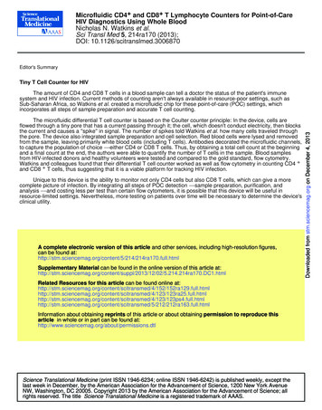
1.2.2 Invader Assay and Single Nucleotide Polymorphism DetectionThe Invader assay (Figure 1.1) is a two-step 63 oC isothermal reaction used to detect singlenucleotide polymorphisms (SNPs) for genotyping. The first step of the Invader assay is therecognition of the SNP in the target DNA and the formation of a highly specific tripartitestructure. This step consists of four main components: a flap endonuclease (FEN), an Invaderoligo, a pair of FAM/RED Invader signal probes, and the target DNA. The Invader oligocontains a complimentary sequence to the 3’ end target DNA up to, but not containing the SNPand binds to the target DNA. Similarly, the Invader signal probe has a complimentary sequenceto the 5’ end target DNA, but contains the complimentary SNP. If the SNP is present on theFigure 1.1: The Invader assay consists of the target DNA, Invader oligonucleotide, flapendonuclease (FEN), and a pair of corresponding FAM (green) and RED (red) Invader signal probesand FRET cassettes. 1) In the primary reaction, both the Invader oligonucleotide and primary probehybridize to the target of interest. An invasive structure is formed from the single-base overlap. Thisforms a 3-dimensional structure that is recognized by the FEN cleavase which 2) cleaves the 5’ Armof the primary probe. 3) In the secondary reaction, the cleaved 5’ arm of the probe binds to theFRET cassette. In this secondary FRET reaction, this structure is recognized by same FEN cleavasewhich 4) cleaves the fluorophore and a fluorescent signal is generated.3
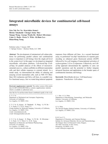
target DNA, the Invader signal probe binds to the Invader oligo-DNA target, forming atripartite structure. The FEN cleavase recognizes this specific structure and cleaves the Invadersignal probe at the site of the SNP, forming a 5’ signal flap. The second step is fluorescencegeneration. The previously cleaved 5’ signal flap binds to a corresponding FAM/RED FRETcassette. The FEN cleavase recognizes this specific structure and cleaves the boundedFAM/RED fluorophore, generating a corresponding FAM/RED signal detected by our opticalsystem. If the SNP was not initially present, the tripartite structure is not formed and thefluorophore remains bounded to the FRET cassette and quenched (no fluorescence isgenerated). Fluorescence was monitored in FAM (excitation: 450-490 nm and emission: 510530 nm) and Texas Red (excitation: 560-590 nm and emission: 610-650 nm).In the assay design stage, 10 polymorphic markers of interest were identified andselected. Each synthetic target set consisted of two oligos, “A” and “B”, corresponding to theFAM (green) allele and the RED (red) allele, respectively. For all 10 markers, the Invaderprobes were designed by Third Wave Technologies. All genomic targets evaluated were knownto be homozygous for FAM or RED. All Invader reagents’ concentrations are optimized byDuPont Pioneer (Johnston, Iowa) and proprietary.1.2.3 Device DesignThe developed programmable microfluidic Invader device (Figure 1.2) consists of twoPDMS layers, utilizing a push-up valve architecture, wherein the bottom valve layer (Figure1.2, red) collapses into an upper fluidic layer (Figure 1.2, green). The fluidic layer features acarrier oil inlet for carrier oil loading, ten probe inlets (Figure 1.2, P1 – P10) for Invaderprobes/reagents, and two unique Nano Sample Processors inlets (Figure 1.2, S1 and S2) forDNA sample processing and sample loading/rinsing. The bottom valve layer featurescorresponding valves aligned underneath each fluidic inlet and channel to automatically control4
the opening and closing of each inlet via a custom, programmable MATLAB script.Consequently, DNA samples are digitalized into daughter droplets via the NSPs separated bythe immiscible carrier oil and injected with its respective Invader probe in the fusion zone.DNA-probe droplets are then mixed in the serpentine channels, incubated in the incubationzone at 63 oC for 20 minutes for the Invader reaction, and detected for its fluorescence readout,before exiting via the outlet. All processes occur in a continuous flow manner, akin to anassembly line, allowing for minimal downtime and processing of an unlimited number ofFigure 1.2: Schematic of Invader microfluidic device. The PDMS microfluidic device consists of2 layers, a bottom valve layer (red) and a top fluidic layer (green). The fluidic layer features 2 NanoSample Processors (S1, S2), 10 probe inlets (P1 – P10), and a carrier inlet. Droplets are generatedin the droplet generation region and then travel through a serpentine channel which promotes dropletmixing. Once mixed, droplets enter the incubation region and are incubated in continuous flow at63 C for 20 minutes. Fluorescence read-out occurs in the detection region, near the outlet of thedevice using Confocal Fluorescence Spectroscopy.5
droplets within the device. With such design, the device can be programmed to analyze multiple,unique DNA samples against a panel of a flexible number of probes. As a proof-of-concept,we screened eight, unique maize DNA samples against a panel of ten Invader probes.1.2.4 Device FabricationFluidic and valve layer masks were designed in L-EDIT v16.0 (Tanner EDA) and printedby CAD/Art Services, Inc. Fluidic and valve layer molds were fabricated on 4-inch siliconwafers (Polishing Corporation of America). The fluidic layer mold was patterned with SPR220-7 (MicroChem Corp.) to form the channel regions (height was 25 µm) to be collapsed bythe valve layer. This was followed by patterning of SU8-3025 (MicroChem Corp.) to generatethe rest of the fluidic channel network (height was 45 µm). For the valve layer mold, a singlelayer of SU8-3025 was patterned on the wafer (height was 45 µm). The molds were used tofabricate the devices by soft lithography. The fluidic layer molds were first silanized usingvapour deposition of chlorotrimethylsilane (Sigma-Aldrich) for 15 minutes. A thick fluidiclayer was then casted using 50 grams of PDMS base to crosslinker ratio (6:1) and degassedunder vacuum conditions for an hour. The fluidic layer was then cured for eight minutes at 80 C. The valve layer (15:1, PDMS base to crosslinker ratio) was spun at 1350 RPM (LaurellTechnologies, Corp.) and baked for 4 minutes at 80 C. After baking, the fluidic layer wasmanually aligned to the valve layer under a stereoscope. Both layers were then baked for 60minutes at 80 C. Access holes were then punched for the inlet and outlet ports and the PDMSdevice was bonded to Thickness #1 cover glass (Ted Pella, Inc.) with oxygen plasma treatment.1.2.5 Device Priming, Hydrophobic Surface TreatmentThe push-up valve architecture of the Invader microfluidic device is compared to thetraditional push-down architecture of most microfluidic platforms. In conventional push-down6
valve architecture, the fluidic channels reside on a hydrophilic glass surface. The bottom glasssurface requires an initial hydrophobic Aquapel (PPG Industries, Pittsburgh, PA) treatment toensure droplet integrity and stability. Aquapel is filtered using a Syringe Durapore (PVDF)membrane filter unit, 33 mm diameter/0.22 μm pore size (Merck Millipore), and manuallyinjected into the device. Aquapel is flushed out with air at 10 PSI followed by FC40 (3M) at10 PSI, filtered using a Syringe Nylon membrane filter unit, 30 mm diameter/0.22 μm pore size(CELLTREAT Scientific Products). The device is placed in an oven at 80 oC for two hours anddegassed in a vacuum. In comparison, in push-up valve architecture, Aquapel treatment is notnecessary and the Invader microfluidic device is directly degassed in a vacuum prior to use.1.2.6 Optimization of Carrier Oil, Additives, and SurfactantsOptimization of carrier oil to be used on-chip was performed for the droplet-based Invaderassay. Different mixtures of fluorinated oils, including: FC-40, FC-3283, HFE-7500, and 1H,1H, 2H, 2H-Perfluoro-1-octanol (Sigma Aldrich) (4:1 v/v) (PFO) were evaluated. The additionof bovine serum albumin (BSA) was found to improve small hydrophobic molecule andfluorophore retention within droplets, but caused droplet sticking in the channels and poordroplet mobility. These results were consistent with those found in the literature (11). A mixtureof FC-40 and PFO offered the optimal balance between droplet stability and small moleculeretention among the carrier oils and surfactants that were evaluated.1.2.7 Device OperationA set of solenoid valves was used to control the opening and closing of individual valves inthe microfluidic device. The solenoid valves were controlled by a custom MATLAB(Mathworks) program. To interface with the microfluidic device, all reagents were loaded into7
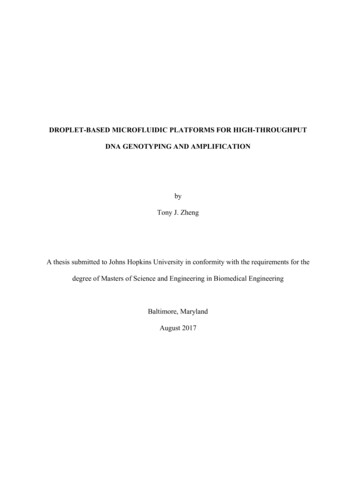
Tygon microbore tubing (Cole-Parmer) and connected with the device through inlet andvalve ports. Valves were pressurized at 15 PSI.The carrier oil, consisting of FC-40 (3M) and 1H, 1H, 2H, 2H-Perfluoro-1-octanol (SigmaAldrich) (4:1 v/v) (PFO), was pressurized at 5 PSI and loaded into the device via the carrierinlet. The Invader device operation is detailed (Figure 1.3). The carrier oil was allowed to filland wet the entire length of the central oil channel prior to droplet generation. All reagent/probeinlets were primed and loaded with its respective reagent/probe mixture. Next, the valveactuation sequence was programmed in MATLAB and executed, corresponding to the DNAprobe droplet combinations to be generated in the device. The digitalized DNA droplet ( 5 nL)then entered the narrowing fusion zone and thus, stretched to span the entire fusion zone. Amixture containing the respective SNP-interrogating probe, enzymes, and FRET cassettes ( 45nL) was injected in a synchronization-free manner directly into the DNA droplet. SubsequentDNA-probe droplets were continuously processed in an assembly-line manner. Each DNAsample was screened against a library of 10 SNP-interrogating probes, resulting in a sequencecontaining 10 droplets of different probe composition per DNA sample processed. Following,each DNA-probe droplet passed through a serpentine channel region to promote mixing priorto entering the incubation region. The incubation region was maintained at a constanttemperature of 63 C for Invader assay. After incubation, in-line fluorescence readout wasperformed on droplets using dual laser spectroscopy, where fluorescence intensity data wascollected and analyzed.8
Figure 1.3: DNA samples are sequentially loaded into the microfluidic device via two NSPs anddigitalized into 5 nL droplets. DNA droplets then arrive in the fusion zone, where the narrowchannel causes the DNA droplets to stretch and span the entire fusion zone, thus allowingsynchronization-free injection of 45 nL Invader probes and reaction mix into the DNA droplets.DNA-probe droplets are incubated for 20 minutes at 63 oC as they flow throughout the incubationregion in continuous flow. In-line readout is performed and fluorescence signals are then used todetermine the final allelic call out for that specific DNA and probe.1.2.8 Fluorescence Detection and Data AnalysisSpectroscopy data was acquired using a custom-built two-color confocal fluorescencespectroscope (CFS), designed to simultaneously detect both FAM and RED Invaderfluorophores within droplets (Figure 1.4). The CFS employs dual laser excitation (488 nm,552 nm) and dual emission channel (506-534 nm and 608-648 nm), dichroic mirrors, opticalband-pass filters, and two silicon avalanche photodiodes (APD) (12). The spectroscopyplatform also includes a trans-illumination LED and CCD camera for bright-field imaging (12).Data analysis was performed using custom scripts written in MATLAB (13). The leading andfalling edge of each droplet were identified as the location in a fluorescence data trace where9
Figure 1.4: The two-color Confocal Fluorescence Spectroscope (CFS) is designed tosimultaneously detect fluorescence signals of both Invader probes within droplets. The CFS systememploys two laser sources for fluorescence excitation, dichroic mirrors (DM), and optical band-passfilters (BF) for routing optics, and two silicon avalanche photodiodes (APDs) for detection offluorescence signals. The instrument includes a trans-illumination LED and CCD camera for brightfield imaging of the droplets in the device.the signal from the FAM fluorescence reached three standard deviations about the backgroundfluorescence of the carrier oil. RED fluorescence data was analyzed at each droplet location,as identified by the FAM signal. Integration time for photon binning was set at 10 ms for allpeak counting experiments. For each sample, four data traces were analyzed with each tracecontaining at least 10 visible droplets. MATLAB was used to identify droplets in a data traceand generate the average intensity and standard deviations for each reaction condition acrossits repeats. The average droplet intensity of each droplet was then used to determine the finalallelic call out for that specific DNA-probe combination. The average fluorescence intensity of10
a DNA-probe combination droplet was divided by the average fluorescence intensity of aprobe-only control droplet. Data was analyzed according to the following calculation (14):𝑅𝐹𝑈𝐹𝐴𝑀Equation 1: log(𝐹𝐴𝑀𝑅𝐸𝐷𝑟𝑎𝑡𝑖𝑜) log 3 Results and Discussion1.3.1 Sample Loading via Nano Sample ProcessorsWe present a programmable, droplet-based microfluidic platform that is capable ofmultiplexed SNP genotyping a library of maize DNA samples against a panel of SNP markers.The device features a unique, high-throughput dual Nano Sample Processor (NSP) technology,robust synchronization-free probe injection, and in-line continuous incubation and detectionfor assay read-out (Figure 1.3). Dual NSPs are designed to optimally load multiple samplessequentially into the device (Figure 1.5). In operation, two NSPs (NSP 1 and NSP 2) arefunctionalized in unison (Figure 1.5A). As NSP 1 digitalizes DNA Sample 1 into daughterdroplets into the central oil channel of the device, the upcoming DNA Sample 2 is pressurizedand loaded into NSP 2 (Figure 1.5A, Step 1). Upon completed droplet generation by NSP 1,the function of each NSP switches. NSP 2 now digitalizes DNA Sample 2 into daughterdroplets, while NSP 1 rinses the previous DNA Sample 1 out of the device and loads theupcoming DNA Sample 3 (Figure 1.5A, Step 2). Continuously, the process repeats, NSP 1returns to droplet generation and digitalizes DNA Sample 3 into daughter droplets, as NSP 2now undergoes rinsing and is ready to load new, subsequent samples (Figure 1.5A, Step 3).As such, when dual NSPs are functionalized in unison, a continuous workflow of sampleloading, droplet generation, and rinsing is achieved without stopping the flow of the dropletsin processing regions downstream in the device, thus minimizing the downtime. This dual NSPtechnology allows for clean and efficient loading and processing of a high number of unique11
DNA samples via only two sample inlets, bypassing current limitations of restricted device sizeand footprint that can only house 10 to 30 inlets. Finally, this design is even more advantageouswhen the dual NSP technology is interfaced with a robotic multi-well sampling system (15),allowing the presented system to be operated in an automatic manner for high throughputsampling applications.A single NSP functions for robust and rapid sample loading, droplet generation, and samplerinsing (Figure 1.5B). The working mechanism for loading multiple samples is visuallydemonstrated using green and yellow dye in a step-by-step manner. First, the sample valve isclosed and the rinse valve is opened as green dye is pressurized and rapidly loaded into theNSP via the sample inlet (Figure 1.5B, Step 1). After loading is completed, the rinsing valveis closed. The sample valve is now actuated, digitalizing the green dye into daughter dropletsinto the central oil channel (Figure 1.5B, Step 2). Daughter droplets’ size can be preciselycontrolled by programmable actuation of the sample valve, precisely tuning the duration ofopening and closing of the valve. Following droplet
professor, Dr. Jeff Wang and to my tremendous and invaluable mentors, Dr. Wen Hsieh, Dr. Helena Zec, and Dr. Divya Nalayanda, for their continuous teachings, mentorship, patience, . teamwork, and discussions, and the rest of Dr. Wang's lab for their supportive advice, feedback, and insights. Lastly, I would like to thank my family and .