Transcription
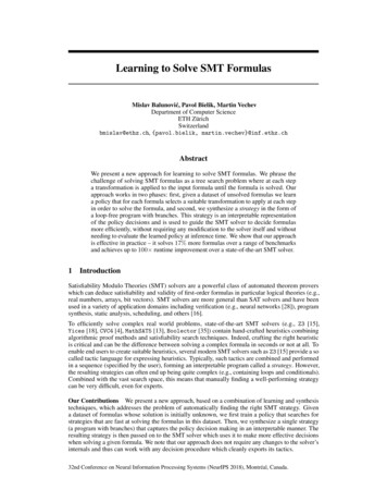
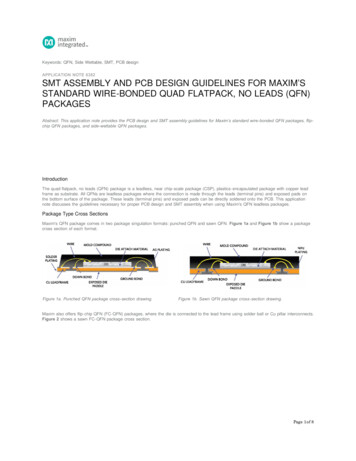
Keywords: QFN, Side Wettable, SMT, PCB designAPPLICATION NOTE 6382SMT ASSEMBLY AND PCB DESIGN GUIDELINES FOR MAXIM’SSTANDARD WIRE-BONDED QUAD FLATPACK, NO LEADS (QFN)PACKAGESAbstract: This application note provides the PCB design and SMT assembly guidelines for Maxim’s standard wire-bonded QFN packages, flipchip QFN packages, and side-wettable QFN packages.IntroductionThe quad flatpack, no leads (QFN) package is a leadless, near chip-scale package (CSP), plastics-encapsulated package with copper leadframe as substrate. All QFNs are leadless packages where the connection is made through the leads (terminal pins) and exposed pads onthe bottom surface of the package. These leads (terminal pins) and exposed pads can be directly soldered onto the PCB. This applicationnote discusses the guidelines necessary for proper PCB design and SMT assembly when using Maxim's QFN leadless packages.Package Type Cross SectionsMaxim's QFN package comes in two package singulation formats: punched QFN and sawn QFN. Figure 1a and Figure 1b show a packagecross section of each format.Figure 1a. Punched QFN package cross-section drawing.Figure 1b. Sawn QFN package cross-section drawing.Maxim also offers flip-chip QFN (FC-QFN) packages, where the die is connected to the lead frame using solder ball or Cu pillar interconnects.Figure 2 shows a sawn FC-QFN package cross section.Page 1 of 8
Figure 2. Sawn flip-chip QFN package cross section.For select end applications, designers may want to visually inspect the solder joint formation on the QFN terminals using an automated opticalinspection tool. For these select applications, designers should consider the side-wettable QFN package option.Maxim's side-wettable QFN package options use geometrical solutions such as half-cut lead frame, half-etch lead frame, or dimpled leadframe to create an externally visible solder joint that can be inspected optically after reflow soldering. Figure 3a shows a dimpled sidewettable QFN drawing, and Figure 3b shows a half-cut side wettable QFN drawing.Figure 3a. Dimpled side-wettable QFN package drawing.Figure 3b. Half-cut side-wettable QFN package drawing.Package Surface Mount ConsiderationsSpecial considerations are needed to properly design the PCB to mount the package. For enhanced thermal, electrical, and board levelperformance, the exposed pad on the package needs to be soldered to the board using a corresponding thermal pad on the board.For proper heat conduction through the board, thermal vias need to be incorporated into the PCB in the thermal pad region. The PCB footprintdesign must be considered from dimensional tolerances due to package, PCB, and assembly. Many factors can have significant effects onmounting the package on the board and the quality of solder joints. Designers must consider these factors, which include the following:Solder paste coverage in the thermal pad regionStencil design for peripheral and thermal pad regionType of vias, board thicknessLead finish on the package, surface finish on the boardType of solder paste and reflow profileThis application note provides designers with the guidelines for board design considering these factors. It should be emphasized that thisdocument is strictly a guideline to help the user in developing the proper motherboard design and surface mount process. Actual studies aswell as development effort may also be needed to optimize the process as per the user's surface-mount practices and requirements.PCB Design GuidelinesPCB Pad DesignA well-designed and manufactured printed circuit board (PCB) is required for optimum manufacturing yields and product performance.Page 2 of 8
Two types of land patterns are used for surface-mount devices:a. Solder Mask Defined (SMD) pads have solder mask openings that are smaller than metal pads.b. Non-Solder Mask Defined (NSMD) pads have solder mask openings that are larger than the metal pads.Maxim recommends the use of NSMD pads because they provide a larger metal area for the solder to anchor to the edges of metal pads onthe board for improved solder joint reliability.Figure 4. Cross section drawing of NSMD. Note: There should not be any mixture of SMD and NSMD pads within the same QFN footprint. Maxim recommendsthe inclusion of fiducial marks in proximity to the QFN package to facilitate component placement.PCB Land Pattern DimensionsMaxim's land pattern drawings for QFN packages can be downloaded from our website at: www.maximintegrated.com/packages. IPC landpattern calculator (IPC-7351) can be downloaded from the IPC website at: www.ipc.org.Maxim does not recommend designing vias, untented with solder mask, close to the package lead terminal and underneaththe corners of the package where tie bars terminate. Refer to IPC-7351 for “Land Pattern to Via Relationship” design recommendation.PCB Pad Pattern for Lead TerminalsAs a guideline, lead finger length dimension (Y) should be designed using the following considerations:0.20mm to 0.5mm longer (extending outwards) than package terminal length for good solder filleting (for standard QFN packages)0.25mm to 0.5mm longer (extending outwards) than package terminal length for good solder filleting (for side-wettable QFN packages)0.05 mm extended towards center line of packageFor lead finger width dimension (X) should be designed using the following considerations:Wider by 0.05mm than package terminal width (i.e., 0.025mm per side), for lead pitch greater than 0.65mmMatch terminal width to minimize risk of solder bridging, for lead pitch 0.65mm and belowFigure 5a. Lead terminal length.Figure 5b. Lead terminal width.Page 3 of 8
PCB Pad Surface FinishThe selection of an appropriate PCB pad surface finish is critical to ensuring optimum manufacturing of the final board assembly. Table 1compares several popular surface finishes.Table 1. Surface Finish OptionsFinishNameDescriptionRecommendation CommentsCopperOSPOrganic solderabilitypreservative (OSP)Acceptable—ENIGElectroless nickel immersion Acceptablegold—SilverImmersionThin layer silver electrolessplatedAcceptableSilver immersion thickness must be controlled (0.150mm to 0.625mm tominimize micro voids at the solder jointGoldImmersionThin layer gold electrolessplatedAcceptable—HASLHot air solder levelingAcceptableProcess must be controlled to provide solder coverage of small maskopeningsStencil Design GuidelinesThe stencil thickness and pattern geometry determine the precise volume of solder paste deposited onto the device land pattern. Stencilalignment accuracy and consistent solder volume transfer is critical for uniform solder reflow. Stencils are usually made of stainless steel.Design Recommendation:Stencil Thickness5 mils: Stencil aperture opening of 1 mil/side smaller than the pad size.4 mils: Stencil aperture opening should be 1:1 to PCB pad sizes.Stencil FabricationLaser-cut with electropolish for better release than the regular laser-cut stencil.Stencil ApertureTolerances must be tightly controlled, specifically for 0.5mm and 0.4mm pitch packages, as these tolerances can effectively reduceaperture sizeWalls of the apertures should be as smooth, with rounded corners, and a trapezoidal cross section (Figure 6) enhances the releaseof solder paste from the aperture.QFN stencil aperture must meet the industry standard area ratio of 0.66.Figure 6. Stencil cross section.Stencil Design for Thermal Pads (Exposed Pads)Recommendation:Smaller multiple opening should be used instead of a single big opening to minimize voiding.50% to 80% solder paste coverageRounded corners to minimize solder paste cloggingPositive taper with bottom opening larger than the topPage 4 of 8
Figure 7. Stenceil design for exposed pads.Solder PasteA low-residue, no-clean solder paste is commonly used in mounting QFNs. Water-soluble flux materials are not recommended as there isminimal standoff (distance of package to PCB) and it will, therefore, be very difficult to clean flux trapped underneath the package.A Type 3 (or finer) solder paste is recommended for 0.5mm pitch printing. Nitrogen purge is recommended during solder reflow.Recommended lead(Pb)-free solder paste: SAC305 (Sn-Ag-Cu) alloysSolder Paste PrintingAn automatic or manual stencil/screen printer can be used to distribute the solder paste onto the PCB lands.A design of experiments (DOE) should always be used to establish optimum printing parameters. Most assemblers find that the followingparameter ranges serve as good starting points:Print head speed: 1–2 inches/secondSqueegee pressure: 0.75–1.5 pound per inch of squeegeeUnder-stencil wiping: Every 3 boardsTemperature: 23 C to 28 CHumidity: 30% to 60% RHA stainless steel squeegee should be used. Multiple printing of solder paste should be avoided for fine pitch devices, as it may causesmearing of the solder paste.Package Placement and AlignmentConventional placement systems can be employed using either the QFN outline or the position of the leads as a placement guide. Placementguide using position of the leads tends to be more accurate but slower, and requires a complex vision processing system. Package outlineplacement method runs faster but is less accurate. The contract PCB assembler can determine the most acceptable method to be employedfor this process. The QFN package is expected to a good self-centering ability similar to a BGA package.Reflow ProfileMaxim QFNs are compatible with all industry-standard solder reflow processes. It is important that profiles be checked on all new boarddesigns. Additionally, if there are tall components mixed on the board, the profile must be checked at different locations on the board.Component temperatures may vary due to surrounding components, locations of parts on the PCB, and package densities.The reflow profile guidelines are based on the temperature at the actual lead to PCB land pad solder-joint location. The actual temperature ofthe solder joint is often different than the temperature settings in the reflow system. It is recommended that reflow-specific profiles be checkedusing thermocouples at the actual solder-joint locations and following the paste supplier's recommendations.Nitrogen reflow is recommended to improve solderability and to reduce defects such as solder balls. Figure 8 is one reflow example for Pbfree temperature profile per JEDEC J-STD-020.Page 5 of 8
Figure 8. JEDEC lead-free reflow profile.Table 2. Recommended Pb-free Reflow ProfileLead (Pb) free reflow profile featureDescriptionPb-Free assembly recommendationTSminMin Soak Temperature150 CTSmaxMax Soak Temperature200 CtSTime Between TSMIN and TSMAX60–120 SecondsTLLiquidous Temperature217 CtLTime Above TL60-150 secondsTPPeak Package Body Temperature260 CtPTime Within 5 C of TP30 SecondsTL to TPRamp-Up Rate3 C/Seconds (max)TP to TLRamp-Down Rate6 C/Seconds (max)—Time 25 C to Peak Temperature8 Minutes (max)Solder Joint Inspection GuidelinePost-reflow inspection of QFNs on PCBs is typically accomplished by using transmission-type X-ray equipment. X-ray can be used for reflowprocess monitoring and as a failure analysis tool. A 2D X-ray system with oblique view at highest magnification (OVHM) is recommended as itcan detect solder bridges, opens, and voids.Solder Joint Visual Inspection RecommendationsStandard QFN packagesStandard QFN packages do not have any externally visible features that allow one to check if the package has been successfully soldered tothe board. As in any leaded package technology, the edges of the leads will have exposed bare copper. Bare copper is not sufficient toensure side wetting.Lack of solder wetting in this area should not be considered as a criterion for visual inspection rejection. Maxim does not guarantee formationon solder fillet (toe fillet) as the sides of these lead terminals will have an exposed copper post-package singulation.Page 6 of 8
Side-Wettable QFN PackagesThe specifically introduced geometric features in a side-wettable package (half-cut/half-etch/dimple) allow for a visible solder fillet to form onthe side of all peripheral pins (Figure 9). The fillet can be visually inspected if the pins are soldered successfully to the PCB pads. The fullheight of the geometrical structure needs to be covered by solder fillet.Figure 9. Half-cut side-wettable and dimpled side-wettable QFN.PCB CleaningIf a low residue, no-clean solder paste is used, PCB cleaning is not required. However, with different types of no-clean solder pastesavailable, Maxim recommends application-specific evaluations be performed to identify if any remaining residue needs to be removed from theboards.Rework GuidelinesAn appropriate rework station should be used for any rework on the parts.Component RemovalPrior to any rework, it is strongly recommended that the PCB assembly be baked for at least 4 hours at 125 C to remove any residualmoisture before component removal.During the removal process, it is recommended that the board be heated from the bottom side using convective heaters, and hot gas or airshould be used on the top side of the component. Special nozzles should be used to direct the heating to the component only and minimizeheating of adjacent components.Maximum part temperature should be above the liquidus temperature of 217 C, but should not exceed 260 C. Once the joints have reflowed,the vacuum lift-off should be automatically engaged during the transition from reflow to cool down. The vacuum pressure should be kept below15in of Hg to ensure the component is not lifted out if all joints have not been reflowed.Site RedressFollowing component removal, the site must be cleaned properly without damaging the pads. Once the residual solder has been removed, thelands should be cleaned with a solvent. The solvent is usually specific to the type of paste used in the original assembly. Pastemanufacturer’s recommendations should be followed.Solder Paste PrintingIt is recommended that a miniature stencil be used to print solder paste on the PCB surface at the component site.Follow stencil thickness, stencil design, solder recommendations, and screen-printing guidelines, as provided for original PCB assembly. Alignstencil with the pads under 50X magnification to inspect the site before replacing with a new component (part).Component PlacementQFN packages have superior self-centering ability similar to BGA packages. Because the leads are on the package’s underside, a split-beamoptical system should be used to align the component on the board. Doing so forms an image of the leads overlaid on the mating footprintand aids in proper alignment. A placement machine having a 0.05mm placement accuracy should be used.ReflowThe same reflow profile developed during initial component attachment should be used to attach the new component followed by the postreflow inspection step.Page 7 of 8
More InformationTechnical Support ›Samples ›More InformationFor Technical Support: https://www.maximintegrated.com/en/supportFor Samples: https://www.maximintegrated.com/en/samplesOther Questions and Comments: ion Note 6382: ON NOTE 6382, AN6382, AN 6382, APP6382, Appnote6382, Appnote 6382 2014 Maxim Integrated Products, Inc.The content on this webpage is protected by copyright laws of the United States and of foreign countries. For requests to copy this content,contact us.Additional Legal Notices: https://www.maximintegrated.com/en/legalPage 8 of 8
For lead finger width dimension (X) should be designed using the following considerations: Wider by 0.05mm than package terminal width (i.e., 0.025mm per side), for lead pitch greater than 0.65mm Match terminal width to minimize risk of solder bridging, for lead pitch 0.65mm and below Figure 5a. Lead terminal length. Figure 5b. Lead terminal width.