Transcription
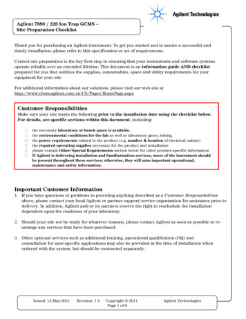
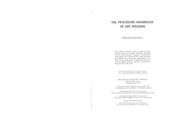
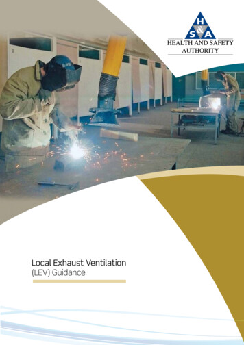
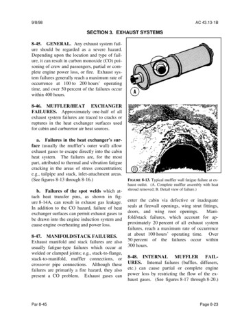
9/8/98AC 43.13-1BSECTION 3. EXHAUST SYSTEMS8-45. GENERAL. Any exhaust system failure should be regarded as a severe hazard.Depending upon the location and type of failure, it can result in carbon monoxide (CO) poisoning of crew and passengers, partial or complete engine power loss, or fire. Exhaust system failures generally reach a maximum rate ofoccurrence at 100 to 200 hours’ operatingtime, and over 50 percent of the failures occurwithin 400 hours.8-46. MUFFLER/HEAT EXCHANGERFAILURES. Approximately one-half of allexhaust system failures are traced to cracks orruptures in the heat exchanger surfaces usedfor cabin and carburetor air heat sources.a. Failures in the heat exchanger’s surface (usually the muffler’s outer wall) allowexhaust gases to escape directly into the cabinheat system. The failures are, for the mostpart, attributed to thermal and vibration fatiguecracking in the areas of stress concentration;e.g., tailpipe and stack, inlet-attachment areas.(See figures 8-13 through 8-16.)b. Failures of the spot welds which attach heat transfer pins, as shown in figure 8-14A, can result in exhaust gas leakage.In addition to the CO hazard, failure of heatexchanger surfaces can permit exhaust gases tobe drawn into the engine induction system andcause engine overheating and power loss.8-47. MANIFOLD/STACK FAILURES.Exhaust manifold and stack failures are alsousually fatigue-type failures which occur atwelded or clamped joints; e.g., stack-to-flange,stack-to-manifold, muffler connections, orcrossover pipe connections. Although thesefailures are primarily a fire hazard, they alsopresent a CO problem. Exhaust gases canPar 8-45FIGURE 8-13. Typical muffler wall fatigue failure at exhaust outlet. (A. Complete muffler assembly with heatshroud removed; B. Detail view of failure.)enter the cabin via defective or inadequateseals at firewall openings, wing strut fittings,doors, and wing root openings.Manifold/stack failures, which account for approximately 20 percent of all exhaust systemfailures, reach a maximum rate of occurrenceat about 100 hours’ operating time. Over50 percent of the failures occur within300 hours.8-48. INTERNAL MUFFLER FAILURES. Internal failures (baffles, diffusers,etc.) can cause partial or complete enginepower loss by restricting the flow of the exhaust gases. (See figures 8-17 through 8-20.)Page 8-23
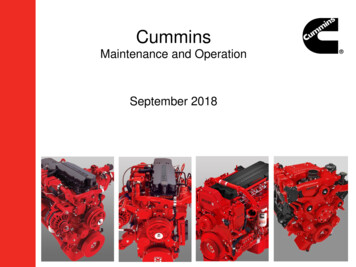
AC 43.13-1B9/8/98FIGURE 8-14. Typical muffler wall failure. (A. Complete muffler assembly with heat shroud removed; B.Detail view of failure; C. Cross section of failed muffler.)As opposed to other failures, erosion and carbonizing caused by the extreme thermal conditions are the primary causes of internal failures. Engine after-firing and combustion ofunburned fuel within the exhaust system areprobable contributing factors.a. In addition, local hot spot areascaused by uneven exhaust gas flow, result inburning, bulging, and rupture of the outer muffler wall. (See figure 8-14.) As might bePage 8-24expected, the time required for these failures todevelop is longer than that for fatigue failures.Internal muffler failures account for nearly20 percent of the total number of exhaust system failures.b. The highest rate of internal mufflerfailures occurs between 500 and 750 hours ofoperating time. Engine power loss and excessive back-pressure caused by exhaust outletblockage may be averted by the installationPar 8-48
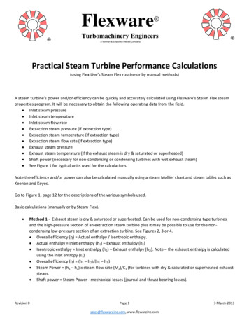
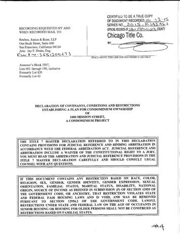
9/8/98AC 43.13-1BFIGURE 8-17. Section of a muffler showing typicalinternal baffle failure.FIGURE 8-15. Typical muffler wall fatigue failure. (A.Complete muffler assembly with heat shroud partiallyremoved; B. Detailed view of failure.)FIGURE 8-16. Typical fatigue failure of muffler endplate at stack inlet.Par 8-48FIGURE 8-18. Loose pieces of a failed internal baffle.Page 8-25
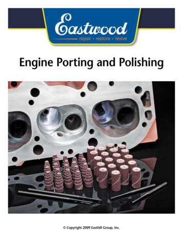
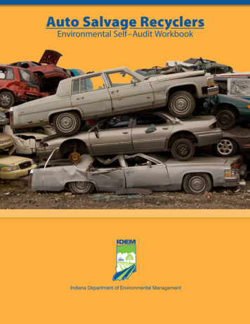
AC 43.13-1B9/8/98of an exhaust outlet guard as shown in figures 8-21a and 8-21b. The outlet guard maybe fabricated from a 3/16-inch stainless steelwelding rod.b. Remove or loosen all exhaust shields,carburetor and cabin heater muffs, shrouds,heat blankets, etc., required to permit inspection of the complete system.Form the rod into two “U” shaped segments,approximately 3 inches long and weld onto theexhaust tail pipe as shown in figure 8-21b sothat the guard will extend 2 inches inside theexhaust muffler outlet port. Installation of anexhaust outlet guard does not negate the importance of thorough inspection of the internalparts of the muffler or the necessity of replacing defective mufflers.c. Perform necessary cleaning operations and inspect all external surfaces of theexhaust system for cracks, dents, and missingparts.Pay particular attention to welds,clamps, supports and support attachment lugs,bracing, slip joints, stack flanges, gaskets,flexible couplings, and etc. (See figures 8-22and 8-23.) Examine the heel of each bend, areas adjacent to welds, any dented areas, andlow spots in the system for thinning and pittingdue to internal erosion by combustion productsor accumulated moisture. An ice pick (orsimilar pointed instrument) is useful in probingsuspected areas. Disassemble the system asnecessary to inspect internal baffles or diffusers.8-49. INSPECTION. Inspect exhaust systems frequently to ascertain complete systemintegrity.CAUTION: Marking of exhaust system parts. Never use lead pencils,carbon based pencils, etc., to markexhaust system parts. Carbon deposited by those tools will cause cracksfrom heat concentration and carbonization of the metal. If exhaust systemparts must be marked, use chalk,Prussian blue, India ink, or a greasepencil that is carbon-free.a. Before any cleaning operation, remove the cowling as required to expose thecomplete exhaust system. Examine cowlingand nacelle areas adjacent to exhaust systemcomponents for telltale signs of exhaust gassoot indicating possible leakage points. Checkto make sure no portion of the exhaust systemis being chafed by cowling, engine control cables, or other components. The exhaust system often operates at red-hot temperatures of1,000 F or more; therefore, parts such as ignition leads, hoses, fuel lines, and flexible airducts, should be protected from radiation andconvection heating by heat shields or adequateclearance.Page 8-26d. Should a component be inaccessiblefor a thorough visual inspection or hidden bynon-removable parts, remove the componentand check for possible leaks by plugging itsopenings, applying approximately 2 psi internal pressure, and submerging it in water. Anyleaks will cause bubbles that can be readilydetected. Dry thoroughly before reinstallation.8-50. REPAIRS. It is generally recommended that exhaust stacks, mufflers, tailpipes, and etc., be replaced with new or reconditioned components rather than repaired.Welded repairs to exhaust systems are complicated by the difficulty of accurately identifyingthe base metal so that the proper repair materials can be selected. Changes in compositionand grain structure of the original base metalfurther complicates the repair. However, whenwelded repairs are necessary, follow the general procedures outlined in Chapter 4; MetalStructure, Welding, and Brazing; of this AC.Retain the original contours and make sure thatPar 8-48
9/8/98AC 43.13-1BFIGURE 8-19. Failed internal baffle partially obstructingthe muffler outlet.FIGURE 8-21a. Example of exhaust outlet guard.FIGURE 8-21b. Example of exhaust outlet guardinstalled.FIGURE 8-20. Failed internal baffle completely obstructing the muffler outlet.the completed repair has not warped or otherwise affected the alignment of the exhaustsystem. Repairs or sloppy weld beads, whichprotrude internally, are not acceptable sincethey cause local hotspots and may restrict exhaust gas flow. All repairs must meet themanufacturer’s specifications. When repairingor replacing exhaust system components, besure that the proper hardware and clamps areused.Do not substitute steel or low-Par 8-50temperature self-locking nuts for brass or special high-temperature locknuts used by themanufacturer. Never reuse old gaskets or oldstar lock washers. When disassembly is necessary replace gaskets with new ones of the sametype provided by the manufacturer.8-51. TURBO-SUPERCHARGER. Whena turbo-supercharger is included, the exhaustsystem operates under greatly-increased pressure and temperature conditions. Extra precautions should be taken in the exhaustsystem’s care and maintenance.DuringPage 8-27
AC 43.13-1B9/8/98FIGURE 8-22. Effect of improperly positioned exhaustpipe/muffler clamp.high-altitude operation, the exhaust systempressure is maintained at, or near, sea levelvalues. Due to the pressure differential, anyleaks in the system will allow the exhaustgases to escape with a torch-like intensity thatcan severely damage adjacent structures. Acommon cause of turbo-supercharger malfunction is coke deposits (carbon buildup) inthe waste gate unit causing erratic system operation. Excessive deposit buildups may causethe waste gate valve to stick in the closed position, causing an overboost condition. Cokedeposit buildup in the turbo-supercharger itselfwill cause a gradual loss of power in flight andlow deck pressure reading before takeoff. Experience has shown that periodic decoking, orremoval of carbon deposits, is necessary tomaintain peak efficiency. Clean, repair, overhaul, and adjust turbo-supercharger systemcomponents and controls in accordance withthe applicable manufacturer’s instructions.8-52. AUGMENTOR SYSTEMS. Inspectaugmentor tubes periodically for proper alignment, security of attachment, and generalPage 8-28FIGURE 8-23. Primary inspection areas.overall condition. Regardless of whether ornot the augmentor tubes contain heat exchanger surfaces, they should be inspected forcracks along with the remainder of the exhaustsystem. Cracks can present a fire or CO hazard by allowing exhaust gases to enter nacelle,wing, or cabin areas.8-53. 8-70. [RESERVED.]Par 8-51
SECTION 3. EXHAUST SYSTEMS 8-45. GENERAL. Any exhaust system fail-ure should be regarded as a severe hazard. Depending upon the location and type of fail-ure, it can result in carbon monoxide (CO) poi-soning of crew and passengers, partial or com-plete engine power loss, or fire. Exhaust sys-tem failures generally reach a maximum rate of